GE Medical Systems CT/i System Service Manual Direction 2152918-100 PDF
Original price was: $95.00.$32.95Current price is: $32.95.
Official GE Medical Systems CT/i System Service Manual — Direction 2152918-100, Revision 22 (2005). All 5 books in one 828-page PDF covering safety, image calibration, system alignments, functional checks, system theory, console/host computer, high voltage & X-ray, DAS & detector, gantry, table, and PDU. Essential for GE CT/i and CTi biomedical service engineers. Includes HSA/CTi tube procedures. Instant download.
Description
GE Medical Systems CT/i System Service Manual Direction 2152918-100 PDF DOWNLOAD
DESCRIPTION
GE Medical Systems CT/i System Service Manual — Complete 5-Book PDF (Direction 2152918-100, Rev. 22)
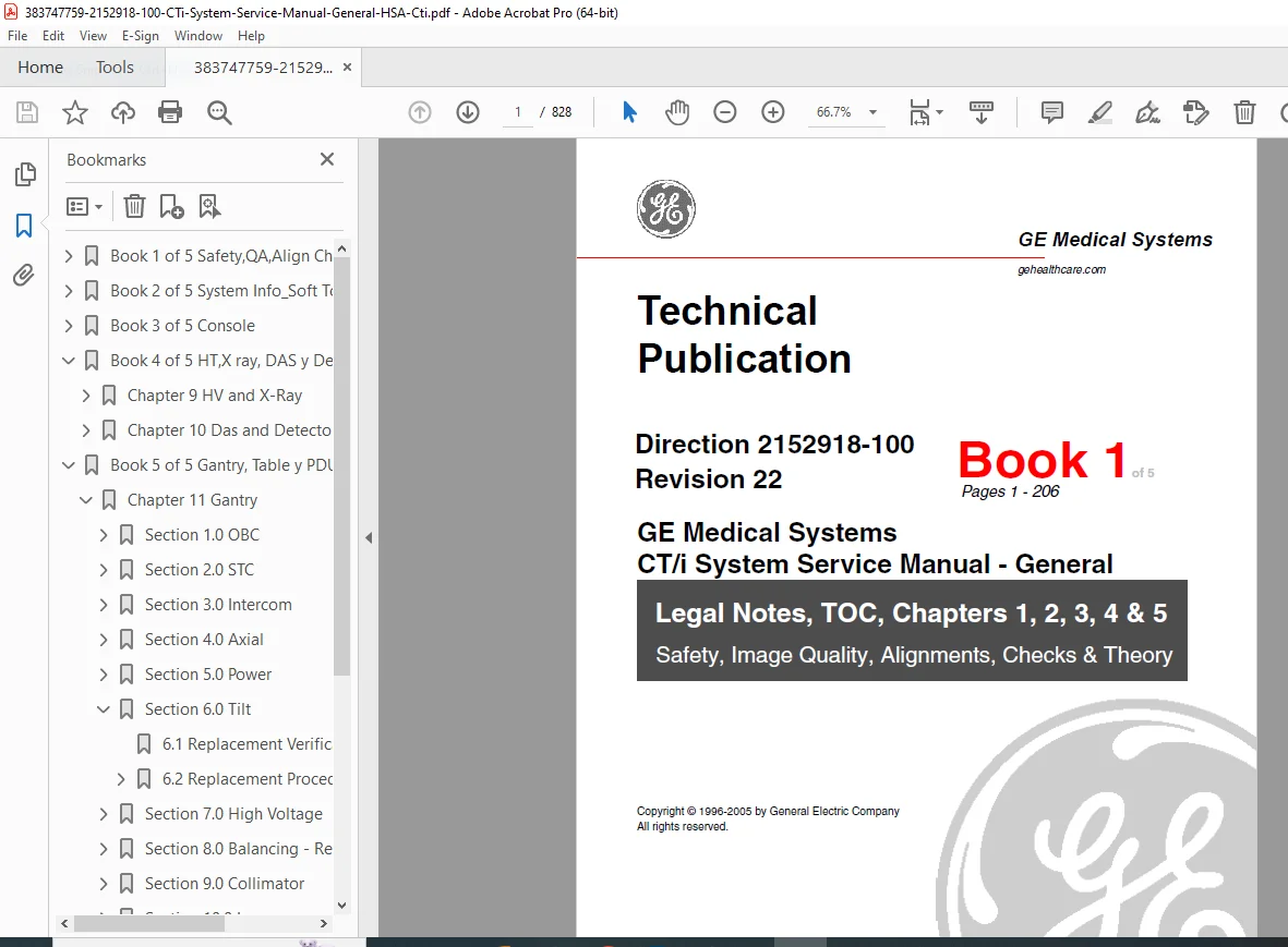
This is the official GE Medical Systems factory service manual for the GE CT/i (CTi) computed tomography system, published under Direction 2152918-100, Revision 22 (December 2005) and authored by GE’s GEMS-AM / CTSE technical publication group. This is the complete 5-book compilation — all 828 pages — used by GE-trained field service engineers for all service, alignment, calibration, replacement, and troubleshooting procedures on the GE CT/i scanner system.
Whether you’re a biomedical service engineer diagnosing a gantry fault, a CT service technician performing image calibration after an X-ray tube replacement, or an independent service organisation needing the exact GE CT/i HSA tube replacement procedure, this manual provides factory-level guidance you cannot find anywhere else.
📋 File Details
| Detail | Info |
|---|---|
| Manual Title | GE CT/i System Service Manual – General |
| Direction Number | 2152918-100, Revision 22 |
| Subject | CT/I System Service Manual – General (HSA/CTi) |
| Models Covered | GE CT/i System (CTi) — HSA and PERFORMIX tube variants |
| Publisher | GE Medical Systems (GEMS-AM, CTSE Technical Publications) |
| Copyright | © 1996–2005 General Electric Company |
| Edition / Revision | Revision 22, December 2005 (22 revisions over 9 years) |
| Language | English |
| Total Pages | 828 Pages (5 Books) |
| PDF Quality | Original factory digital publication — clean, US Letter format |
| File Size | ~11.9 MB |
📚 Full Table of Contents — All 5 Books
📗 Book 1 — Pages 1–206 Chapters 1–5: Safety, Image Quality, Alignments, Checks & Theory
Preface — Publication Conventions
- Safety & Hazard Information (text, graphical, character representation)
- Standard paragraphs, page layout, computer screen I/O conventions
Chapter 1 — Information Sources, Quality & Safety
- CT/i General Publications & Customer Software
- HSA Service Publications
- Safety & System Quality Considerations:
- System dangers and precautions
- General safety requirements
- Torque wrenches & specifications
- Metric hardware cross reference
- Slip ring considerations
- ESD & device handling (electrostatic discharge, proper ESD handling)
- Electromagnetic Compatibility (EMC / EMI) — maintaining CE compliance
- Replacement test and verification philosophy & instructions
Chapter 2 — Image Calibration
- Introduction to the calibration process
- Prepare the QA phantom
- Check for Cal Files
- Calibration Process “A” — When NO Cal Files Exist
- Calibration Process “B” — When Cal Files Exist
- How to Scan with Protocols
- ‘N’ Number Check
- How to Analyze Calibration Data
- System Tests
- Table/Gantry Alignment Procedure
- Tomographic Plane Indication
- Exposure Time Accuracy
- System Scanning Test
- Image Series Scan Protocol:
- Recommended scan parameters & failure criteria
- Leveling the phantom
- Image troubleshooting
- Data recording — means and standard deviation
- Image series definitions for CT/i
- QA image series
- Analyze QA Image Series:
- Image data sheets for QA#1, QA#2, QA#3 scans and evaluation
- System State MOD
- Tube Heat Soak and Seasoning
- Thermal Test
- Cradle Incrementation Test
- Artifacts:
- Center Smudge (definition, method of measurement)
- Reference Mean (failure, application, failure rate)
- Rings (definition, measurement method)
- Artifacts caused by collimator grease — G5 collimator
Chapter 3 — System Alignments
- Overview & gantry geometry definitions
- System alignment procedure & required tools
- Plane of Rotation (POR) — 10 mm and 1 mm exposure procedures
- X-Ray Beam on Detector Window (BOW)
- Isocenter (ISO):
- Acquire ISO air scans, pin scans
- Analyze ISO scans
- Adjust isocenter
- CBF (Center Body Filter) and SAG — adjusting CBF, SAG procedure
- Radial Alignment — cold tube, tool placement, scan, radial adjustment
Chapter 4 — Functional Checks
- Input (PDU) Power
- Gantry Display Test
- Power Supplies: ETC, STC, OBC, HP-DAS, E-DAS, Data Communication, Detector Heater, Filament, Tilt/Elevation (+170VDC), Collimator
- Axial Motion — Axial encoder check, axial brake check
- Intercom
- Alignment Lights (Accuracy) — Internal axial, external axial, coronal lights, visualization
- Emergency Stop
- Collimator
- Mechanical Characterization Procedure:
- Characterization inputs, gantry tilt position
- Table elevation characterization
- Cradle characterization
- Collimator characterization
- Hardware reset, characterization limits, view values/log
Chapter 5 — System Theory
- Data Acquisition (Major Function):
- Scan data acquisition, save, trigger generation (DAS trigger circuitry, PLL 82C54 counters, DAS trigger counter 68230)
- Detector heater, SBC processing, OC processing
- Image Generation (Major Function):
- Data restore, preprocessing, back projection, IBO, post processing, image transfer, suite network, image save, scout image transfer
- System Communications (Major Function):
- SBC boot link, control network, suite network
- Slipring communications (DAS data transfer, CPU comms, scan control)
- DAS serial control, final scan / autovoice control
- Autovoice/Intercom — gantry microphones, speakers, console microphone, ALC, intercom board, speech frequencies
- Security link, scan control network
- X-Ray Generation (Major Function):
- X-ray exposure interlocks, final exposure command
- DC HV supply backup contactor interlock
- Table–gantry sync
- Tube Rotor Control — HSA Tube (CTVRC power module, tube motor)
- Tube Rotor Control — PERFORMIX Tube (HEMRC interface board, HEMRC AC drive, HEMIT, tube motor)
- kV Loop (KV board 46-321064G1 and 46-321198G1/2143147, HV supplies, inverters)
- mA Loop, tube cooling, tube identifiers, tube pressure sense
- X-Ray Collimation and Filtration (collimator control board, X-ray filtration)
- Filament select, rotating HVON control, rotating backup timer
- Calibration Processing (Major Function): Cal data processing, save, SBC/OC processing, diagnostic data save
- Patient Positioning (Major Function): Loading, scanning, alignment lights, scan plane angle (tilt), vertical/longitudinal position
- Axial Control
📘 Book 2 — Pages 207–312 Chapters 6–7: System Information & Software Tools
Chapter 6 — System Information
- Operating System (OS): Time/date, user choices (screen saver, mouse, keyboard language), computer/console power-up and initialisation (Indigo and Octane host bootup)
- System configuration and OS-level administration
- UNIX shell commands, super user access, application restart procedures
Chapter 7 — Software Tools
- Service Desktop Main Menu — introduction, menu function descriptions
- Procedural user interface, desktop inter-operability
- Service Desktop management, clean-up, exit procedures
- System resets
- Troubleshoot menu
- Utilities menu
- Screens: Troubleshooting, replacement procedures, planned maintenance, system integration (general service)
📙 Book 3 — Pages 313–484 Chapter 8: Console (Host Computer & Scan Recon)
Chapter 8 — Console
- Introduction
- CT/i (Octane™) Host Computer:
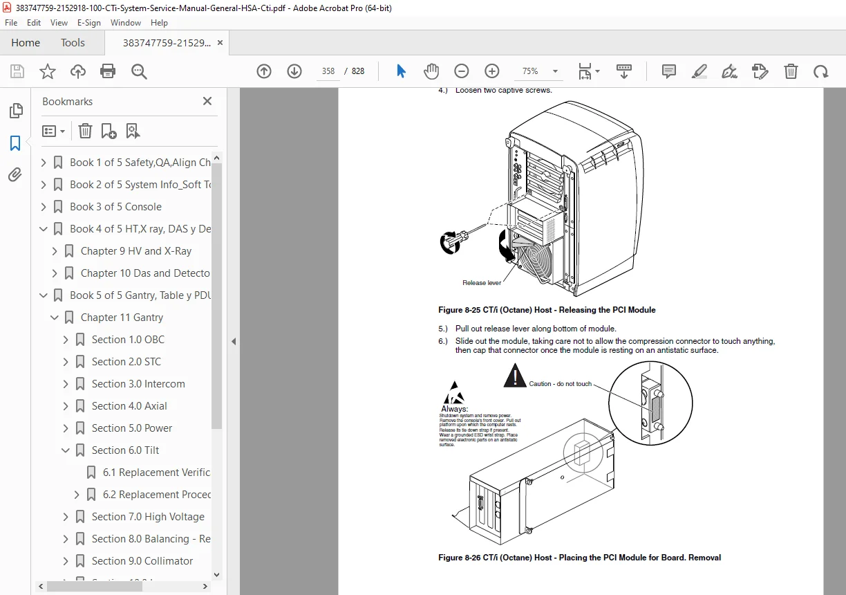
- Octane host overview, main (DIMM) memory, SCSI, PCI
- Octane connectors, controls, serial expansion
- Console hardware and scan reconstruction system
- Host computer diagnostics and replacement procedures
📕 Book 4 — Pages 485–656 Chapters 9–10: High Voltage & X-Ray, and DAS & Detector
Chapter 9 — High Voltage & X-Ray
- X-ray tube replacement procedures (46-309500G1)
- HSA tube procedures — anode and cathode inverter (Section 26.0, updated Rev. 21)
- High voltage supply diagnostics and replacement
- kV/mA system service and adjustment
Chapter 10 — DAS & Detector
- Replacement verification and re-test
- DAS replacement preparation and tests
- Detector replacement and tests
- Diagnostic Data Collection (DDC) — overview, scanning and data processing requirements
- DAS board diagnostics, detector troubleshooting
📒 Book 5 — Pages 657–828 Chapters 11–13, Index & Glossary: Gantry, Table, and PDU
Chapter 11 — Gantry
- OBC (On-Board Computer):
- Replacement verification and re-test
- Component replacement: OBC fan (46-220234P3), RCOM board (46-264700G1), OBC Heurikon CPU board (46-296377P1), Gantry I/O board (46-288512G1), OBC backplane (46-264660G1), OBC thermistor (46-297603G1), OBC ribbon cable (46-297445P1)
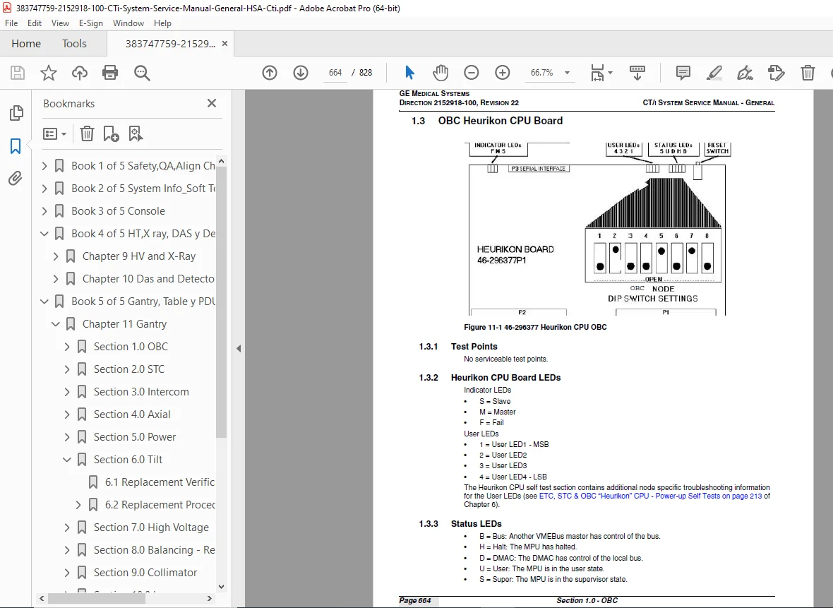
- OBC Heurikon CPU board test points, LEDs (status LEDs), switch settings
- Slipring system (including S/A style slipring updates)
- Gantry mechanical and electrical service
Chapter 12 — Table
- Replacement verification and re-test
- Table Replacement Procedures (37 procedures including):
- AC/DC power switch (46-297093P1)
- Actuator cover, actuator limit switch (46-296561P10), actuator magnet rod, table elevation actuator (46-296561P1 / 2103043)
- Cradle drive belt (46-221532P18)
- Elevation encoder belt (46-170047P7)
- BNC T-connector (46-297332P1)
- Upper pin actuator bumper disk (46-297350P1)
- And 28 additional table component replacement procedures
Chapter 13 — Power Distribution Unit (PDU)
- PDU safety warning
- PDU replacement verification and re-test
- Component locations (GPDU Model 2113764 & CPDU Model 2133533)
- Ground bus continuity check (GPDU)
- PDU Component Details:
- Line transformer settings
- Westamp servo amplifier hardware
- Additional PDU electrical components
Appendix A — Torque Specifications
Index & Glossary — Comprehensive alphabetical index and CT/i terminology glossary
🔧 Who Needs This Manual?
- ✅ GE CT/i biomedical service engineers performing planned maintenance or fault diagnosis
- ✅ Independent CT service technicians performing GE CTi X-ray tube or HV supply replacement
- ✅ Radiology department engineers performing CT/i image calibration and QA phantom procedures
- ✅ Workshop engineers troubleshooting GE CT/i gantry, table elevation, or DAS faults
- ✅ Service organisations needing GE CT/i HSA CTi slipring, OBC, or PDU service data
- ✅ Anyone needing the complete GE CTi system service manual PDF without waiting for a physical copy
GE CT/i service documentation is notoriously difficult to source — and every hour your scanner is offline costs thousands. Download this complete 828-page factory manual instantly, and have the exact calibration procedure, alignment spec, or replacement step at your fingertips before your next service call. This is factory data, available right now.