GE Responder 2000 Service Manual Defibrillator Repair Guide PDF Download
Original price was: $95.00.$30.95Current price is: $30.95.
Complete factory service manual for GE Responder 2000 defibrillator/monitor. This comprehensive 142-page technical guide provides detailed repair procedures, component replacement instructions, safety testing protocols, and performance verification for biomedical technicians. Covers disassembly, ECG testing, defibrillation therapy verification, SpO2 calibration, and complete parts lists. Essential documentation for hospital clinical engineering departments servicing emergency defibrillators.
Description
GE Responder 2000 Service Manual Defibrillator Repair Guide PDF Download
DESCRIPTION
Official Factory Service Manual for GE Responder 2000 Defibrillator/Monitor
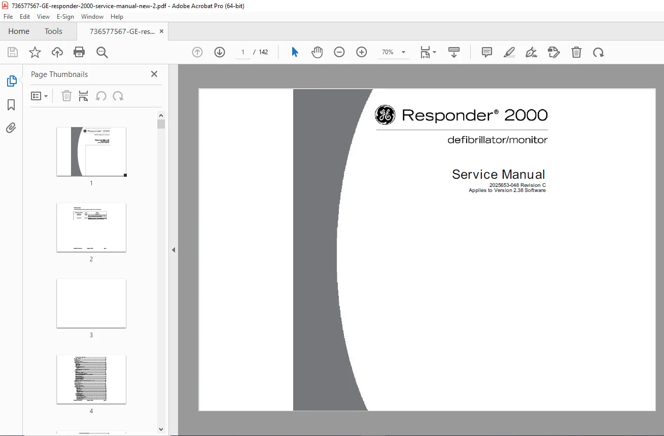
This GE Responder 2000 service manual is the complete factory technical resource for biomedical equipment technicians servicing the Responder 2000 defibrillator/monitor system. With 142 pages of comprehensive technical documentation, this GE defibrillator repair guide provides professional-grade disassembly procedures, component replacement instructions, safety testing protocols, and performance verification tests essential for maintaining this critical life-saving equipment.
FILE DETAILS
| Detail | Information |
|---|---|
| Manual Name | GE Responder 2000 Service Manual |
| Equipment Model | Responder 2000 Defibrillator/Monitor |
| Manufacturer | GE Healthcare (formerly Marquette) |
| Part Number | 2025653-048 |
| Revision | Revision C (Latest) |
| Software Version | Applies to Version 2.38 Software |
| Publication Date | February 2008 (Revision C) |
| Total Pages | 142 |
| PDF Quality | High-resolution factory document |
| Language | English |
| File Size | 5.6 MB |
| Format |
REVISION HISTORY
This is Revision C – the most current version with important updates:
- Initial Release (Rev A): October 2006
- Revision B: October 2007 – Updated LCD cable routing, software v2.22, added Hellige test lamp safety info
- Revision C: February 2008 – Updated Phillips to Torx screw specifications, contact information updates, software v2.38 updates
COMPLETE SECTION-BY-SECTION CONTENTS
SECTION 1: INTRODUCTION (Pages 8-15)
- Overview – Service manual purpose and scope
- Description:
- Responder 2000 system overview
- Defibrillator/monitor capabilities
- Therapy modes and features
- Patient monitoring functions
- Controls and Indicators:
- Front panel controls identification
- LED indicators and meanings
- Display screen elements
- Audio indicators
- Paddle controls
- Trim knob operation
- General Service Information:
- Service precautions and safety warnings
- ESD (Electrostatic Discharge) protection
- Required service documentation
- Operator’s manual reference
SECTION 2: TROUBLESHOOTING (Pages 16-25)
- Systematic Troubleshooting Approach:
- Problem identification methodology
- Symptom-based diagnostics
- Error message interpretation
- LED indicator diagnostics
- Common Problems and Solutions:
- Power-Related Issues:
- Unit won’t power on
- Battery not charging
- Inadequate battery runtime
- Power supply failures
- Display Problems:
- No display / blank screen
- Display dim or flickering
- Backlight failures
- Distorted display
- Defibrillation Issues:
- Won’t charge to selected energy
- Charge takes too long
- Energy delivery inconsistent
- Paddles not functioning
- Pads interface problems
- ECG Monitoring Problems:
- No ECG waveform displayed
- Noisy or erratic ECG
- Lead detection failures
- Incorrect heart rate display
- Pacing Problems:
- Pacing pulses not delivering
- Pacing capture inconsistent
- Pacing rate incorrect
- SpO2 Monitoring Issues:
- No SpO2 reading
- Erratic SpO2 values
- Sensor not detected
- Printer Malfunctions:
- Printer not advancing paper
- Poor print quality
- Printer motor failures
- Audio Problems:
- No alarm tones
- Incorrect audio indicators
- Speaker failures
- Service Required LED Issues:
- Service Required LED is ON – diagnostic procedures
- Power-Related Issues:
SECTION 3: REPAIR (Pages 26-49)
- Overview – Repair procedures introduction
- Required Tools:
- Screwdrivers (Torx specifications)
- ESD wrist straps and mats
- Multimeter
- Torque tools
- Cable ties and fasteners
- Disassembly Overview:
- Step-by-step disassembly sequence
- Component access procedures
- Cable routing documentation
- Fastener identification
- How to Replace Specific Components:
- Capacitors:
- High-voltage capacitor removal
- Discharge procedures
- Installation and testing
- Therapy Board:
- Therapy PCBA removal procedures
- Connector disconnection sequence
- Installation and verification
- SpO2 Board:
- SpO2 PCBA removal
- Interface cable handling
- Replacement procedures
- ECG Board:
- ECG PCBA removal
- Patient connection interface
- Installation procedures
- Display/Main Board/Printer:
- LCD display removal
- Main board (CPU) replacement
- Printer mechanism service
- Cable routing and connections
- Power Supply and Power Control Board:
- Power supply module removal
- Power control PCBA service
- AC power interface
- Battery connections
- Switches and Fan:
- UI switches replacement
- Cooling fan service
- Encoder (trim knob) replacement
- Capacitors:
- Assembly Procedures:
- Overview – Reassembly sequence
- Paddle Latch Assembly – Detailed installation
- Main Board and Printer Installation:
- Motherboard mounting
- Printer head installation
- Printer motor connections
- Cable routing illustrations
- Power Control Board and Power Supply Installation:
- Power supply mounting
- Power control board installation
- DC power distribution
- Battery interface connections
- ECG Board Installation:
- ECG PCBA mounting
- Patient cable interface
- Shielding and grounding
- Display Installation:
- LCD panel mounting
- Backlight (CCFL) connections
- Display cable routing
- SpO2 Board Installation:
- SpO2 PCBA mounting
- Sensor interface connections
- Therapy Board Installation:
- Therapy PCBA mounting
- High-voltage connections
- Paddle/pad interfaces
- Capacitor Installation:
- High-voltage capacitor mounting
- Safety procedures
- Connection verification
- Rear Cover Installation:
- Final assembly procedures
- Seal verification
- Fastener torque specifications
SECTION 4: PERFORMANCE VERIFICATION AND SAFETY TESTING (Pages 50-87)
- Overview – Testing requirements and procedures
- Required Equipment:
- Defibrillator analyzer
- Biomedical test equipment
- ECG simulator
- SpO2 simulator
- Hipot tester
- Leakage current tester
- Multimeter
- Safety analyzer
- Preventive Maintenance:
- Maintenance schedule
- Inspection procedures
- Component life expectancy
- Annual Inspection:
- Complete inspection checklist
- Documentation requirements
- Compliance verification
- Verify Operation:
- Checkout Procedures:
- Power-on self-test verification
- Display functionality
- All controls and indicators
- Audio system check
- Checkout Procedures:
- Maintenance Menu Reference:
- Service Tests:
- Button Test – Verify all control functions
- Printer Speed Test – Printer mechanism verification
- Battery Readings – Voltage and capacity
- Display Test – LCD functionality
- ECG Lead Test – Lead detection verification
- Temperature Readings – Internal temperature monitoring
- Fan Test – Cooling system verification
- Device Configuration:
- Select Language options
- Stored Data Management:
- Clear Event Logs
- Clear Service Required Indicator
- Clear Settings Menu Password
- Clear All Stored Data
- Send Event Logs to PC
- Send/Receive Stored Parameters
- Service Tests:
- Visual Inspection:
- Case and housing integrity
- Cable and connector condition
- Display condition
- Paddle/pad condition
- Battery condition
- Operational Tests:
- Initial Power Up:
- Self-test verification
- Display boot sequence
- Audio prompt verification
- Maintenance Mode Tests:
- Accessing service menu
- Running diagnostic routines
- Verify Serial Communications:
- RS-232 interface testing
- Data transfer verification
- Required equipment and procedures
- Initial Power Up:
- Defibrillator Tests:
- Energy Timeout Test:
- Charge timeout verification
- Safety system testing
- Defibrillator Test Chart:
- Complete energy delivery verification
- All energy levels testing (50J to 360J)
- Impedance compensation verification
- Paddles Test:
- Paddle discharge testing
- Paddle ECG monitoring
- Paddle switch functionality
- Pads Test:
- External pad discharge testing
- Pad interface verification
- Spoons Test:
- Internal paddle testing (if equipped)
- Energy Timeout Test:
- Pacing Test:
- Pacing output verification
- Rate accuracy testing
- Current output measurement
- Capture detection
- ECG Tests:
- Required equipment (ECG simulator)
- ECG Connections Test:
- All lead connections verified
- Proper waveform display
- Lead Detection Test:
- Lead-off detection verification
- Lead fault indication
- ECG Lead Test:
- Waveform accuracy
- Heart rate calculation
- QRS detection
- Paddles ECG Test:
- Quick-look ECG functionality
- Paddle electrode monitoring
- Thermal Printer Operation:
- Print quality verification
- Paper advance testing
- Recording accuracy
- Cardioversion Test:
- Sync mode operation
- R-wave detection
- Synchronized discharge
- SpO2 Operation:
- SpO2 accuracy testing
- Pulse rate accuracy
- Sensor detection
- Safety Tests:
- Hipot Test:
- Required equipment specifications
- ECG to Serial 4.0 KVAC Test
- AC Line/Neutral to AC Ground 1.5 KVAC Test
- ECG to SpO2 1.5 KVAC Test
- Apex Test Load to Apex and Sternum 3.0 KVDC Test
- ECG to Apex and Sternum 3.0 KVDC Test
- Apex and Sternum to Service Port 3.0 KVAC Test
- Leakage Current Test:
- Required equipment specifications
- Equipment setup procedures
- Test procedure step-by-step
- Hipot Test:
- Alternate Safety Test Procedures:
- **Test Equipment specifications
- **Leakage Current “Measurement Device” (MD) Characteristics
- Comprehensive Safety Tests:
- Visual Inspection requirements
- Leakage Current measurements
- Patient Leakage Current to Ground
- Patient Leakage Current, Mains on Applied Part (All SIP/SOPs Grounded)
- Insulation Resistance testing
SECTION 5: PARTS AND ACCESSORIES (Pages 88-97)
- Overview – Parts identification and ordering
- Kits:
- Complete replacement kits with part numbers
- Board assembly kits
- Repair kits
- Maintenance kits
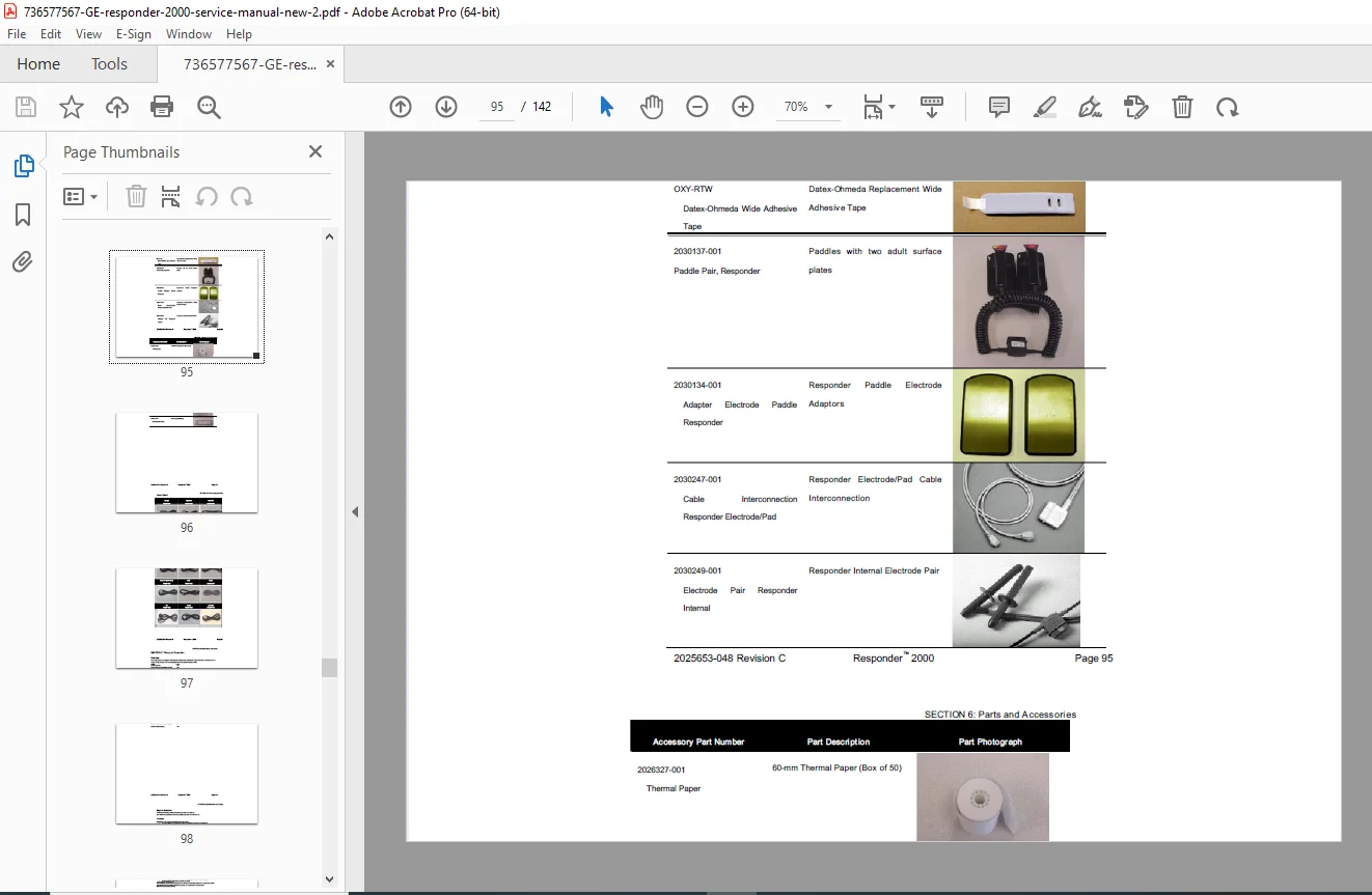
- Accessories:
- Paddles and paddle accessories
- Pads and pad cables
- ECG cables (3-lead and 5-lead)
- SpO2 sensors
- Printer paper
- Batteries
- Mounting hardware
- Carry cases
- Power Cords:
- Regional power cord specifications
- Part numbers for different countries
- AC power requirements
SECTION 6: THEORY OF OPERATION (Pages 98-102)
- Overview – System architecture and design
- System Overview:
- Functions:
- Defibrillation therapy delivery
- Cardioversion (synchronized)
- External pacing
- ECG monitoring
- SpO2 monitoring
- Event recording
- Features:
- STAR Biphasic waveform technology
- RhythmX® ECG analysis algorithm
- Automatic rhythm analysis
- Manual override capabilities
- Data storage and recall
- Functions:
- System Interconnection Block Diagram:
- Complete system architecture
- Board-to-board connections
- Signal flow diagrams
- Power distribution
- Component Descriptions:
- Main Board:
- CPU and processing
- Memory architecture
- I/O interfaces
- Therapy Board:
- High-voltage generation
- Energy storage capacitors
- Discharge control
- Impedance compensation
- ECG Board:
- Patient signal acquisition
- Lead detection
- Signal processing
- Artifact rejection
- Power Control Board:
- Battery charging
- Power management
- AC/DC conversion
- Battery monitoring
- SpO2 Board:
- Oximetry signal processing
- Sensor interface
- Pulse detection
- Main Board:
SECTION 7: SPECIFICATIONS AND SAFETY (Pages 103-121)
- Overview – Technical specifications reference
- Specifications:
- Defibrillation:
- Energy range: 2J to 360J
- Waveform type: STAR Biphasic
- Charge time specifications
- Energy accuracy
- Cardioversion:
- Sync mode operation
- R-wave detection
- Energy delivery
- Pacing:
- Pacing modes
- Rate range
- Current output range
- ECG Monitoring:
- Lead configurations (3-lead, 5-lead)
- Bandwidth
- Sensitivity
- Heart rate range
- SpO2 Monitoring:
- Measurement range
- Accuracy specifications
- Pulse rate range
- Recorder:
- Thermal printer specifications
- Recording speed
- Paper specifications
- Defibrillation:
- Physical Dimensions:
- Length, width, height
- Weight specifications
- With and without battery
- Environmental Requirements:
- Operating Conditions:
- Temperature range
- Humidity range
- Altitude limitations
- Storage and Shipping Conditions:
- Temperature extremes
- Humidity extremes
- Operating Conditions:
- RhythmX® ECG Analysis Algorithm:
- Detection Rate – Rhythm analysis accuracy
- Fine VF – Fine ventricular fibrillation detection
- Asystole – Asystole recognition
- Noise Detection – Artifact rejection
- Non-Committed Shock – Safety features
- Sync Mode – Cardioversion operation
- SVT (Supraventricular Tachycardia) Discriminators
- SVT Rate – Rate discrimination
- Continuous Monitoring For Shockable Rhythm
- Pacemaker Pulse Information – Pacemaker detection
- STAR Biphasic Defibrillation Waveform:
- Waveform characteristics
- Energy levels and patient impedance compensation
- Clinical advantages
- Electromagnetic Compatibility Requirements:
- Emissions:
- RF emissions (CISPR 11)
- Harmonic emissions
- Voltage fluctuations
- Immunity:
- Electrostatic discharge
- Radiated RF
- Conducted RF
- Electrical fast transient/burst
- Surge immunity
- Voltage dips and interruptions
- Power frequency magnetic field
- Electromagnetic Emissions Table – Complete test results
- Electromagnetic Immunity Table – Immunity levels
- RF Communications Table – Recommended separation distances
- Emissions:
- Environmental Standards:
- Shock and Vibration:
- Drop test specifications
- Vibration resistance
- Storage and Shipping:
- Packaging requirements
- Environmental protection
- Shock and Vibration:
SECTION 8: CONNECTORS (Pages 118-139)
- Complete Connector Specifications and Pinouts:
- Case Connectors:
- Power Connector – IEC 320 type – AC Power
- Paddles/Pads Connector – GE Defibrillator Paddles:
- Paddle Connector ID Codes
- Pin assignments
- ECG Connector – GE ECG Connector – Five lead ECG:
- ECG Cable Identification Encoding
- Lead wire assignments
- SpO2 Connector – GE SpO2:
- Sensor interface pinout
- Serial Service Connector – DB9-Female:
- RS-232 pinout and protocols
- Paddle Cradles (Test Load):
- Internal test load specifications
- Main CPU PCBA Connectors:
- J211 – Power Control Interface
- J214 – LCD Panel connection
- J213 – LCD CCFL Backlight
- J218 – UI Interface to Power Control PCBA
- J216 – SPEAKER
- J219 – PRINTER HEAD
- J220 – PRINTER MOTOR
- J221 – SpO2 INTERFACE
- J210 – THERAPY PCBA interface
- J212 – ECG PCBA interface
- Therapy PCBA Connectors:
- J103 – Power Supply
- J110 – Main CPU PCBA interface
- J109 – Paddles Control Connector
- J101, J102, J108 – Paddles HV Connectors
- J104, J105, J106, J107 – Energy Storage Capacitor Connectors
- J126, J127 – Internal Test Load Resistor
- ECG PCBA Connectors:
- J412 – Interface to main CPU PCBA
- J423 – Patient ECG Connection
- Power Control PCBA Connectors:
- J315 – Power input from DC power supply
- J325 – Smart Battery Connector – Data and Power
- J303 – Therapy power
- J311 – Power Control interface from main CPU PCBA
- J318 – UI Features – Interface to main CPU PCBA
- J317 – RS-232 SERIAL SERVICE INTERFACE
- J323 – FAN
- J324 – ENCODER “Trim Knob”
- J2 – SpO2 HOST INTERFACE
- SpO2 PATIENT INTERFACE
- Power Supply Module:
- TB1 – POWER INPUT
- POWER OUTPUT specifications
- Battery:
- J325 – Smart Battery Connector – Data and Power
- Battery management interface
- Case Connectors:
APPENDIX: CONTACT INFORMATION/CUSTOMER SERVICE (Page 140)
- GE Healthcare customer service contact details
- Technical support information
- Parts ordering procedures
- Service training information
WHO NEEDS THIS GE RESPONDER 2000 SERVICE MANUAL?
✓ Biomedical Equipment Technicians (BMETs) – Service and repair defibrillators in hospital and emergency settings
✓ Clinical Engineering Departments – Maintain life-saving defibrillation equipment
✓ Emergency Medical Services (EMS) – Service ambulance and emergency defibrillators
✓ Independent Medical Equipment Service Companies – Provide authorized service for GE equipment
✓ Hospital Equipment Managers – Understand maintenance requirements for critical equipment
✓ Fire Department Medical Units – Maintain first responder defibrillators
✓ Medical Equipment Training Centers – Teach defibrillator service and safety testing
✓ Healthcare Technology Management Professionals – Ensure regulatory compliance
KEY BENEFITS OF THIS DEFIBRILLATOR SERVICE MANUAL
Official Factory Documentation – Authentic GE Healthcare technical manual with manufacturer-approved procedures ensuring accurate service information.
Complete System Coverage – All Responder 2000 subsystems covered including therapy delivery, ECG monitoring, SpO2, pacing, and recording.
Reduce Service Costs – Perform maintenance and repairs in-house, reducing expensive third-party service contracts.
Minimize Equipment Downtime – Quick diagnostic procedures restore life-saving equipment rapidly in emergency situations.
Safety Compliance – Complete electrical safety testing procedures for regulatory compliance and patient safety.
Accurate Parts Identification – Official GE part numbers ensure ordering correct replacement components.
Performance Verification – Comprehensive testing protocols verify equipment meets factory specifications.
Defibrillator Analyzer Testing – Complete energy delivery verification procedures at all energy levels.
GE RESPONDER 2000 DEFIBRILLATOR/MONITOR
The GE Responder 2000 is a professional defibrillator/monitor designed for emergency departments, cardiac care units, ambulances, and first responder applications. This advanced device delivers STAR Biphasic defibrillation therapy with impedance compensation, automatic rhythm analysis using RhythmX® algorithm, external pacing, comprehensive ECG monitoring, and SpO2 monitoring.
This Responder 2000 technical documentation covers the complete system including high-voltage therapy delivery, patient monitoring, thermal recorder, battery power management, and safety systems that make this a trusted emergency cardiac care device.
TECHNICAL SYSTEM HIGHLIGHTS
STAR Biphasic Technology:
- Impedance-compensating biphasic waveform
- Energy range: 2J to 360J
- Rapid charge times
- Higher success rates than monophasic
RhythmX® ECG Analysis:
- Automatic rhythm analysis
- Shockable rhythm detection
- VF/VT recognition
- Asystole detection
- Pacemaker pulse detection
- Noise and artifact rejection
Therapy Capabilities:
- Defibrillation (manual and automated)
- Synchronized cardioversion
- External pacing (demand and fixed rate)
- Paddle and pad compatibility
Patient Monitoring:
- 3-lead and 5-lead ECG
- Paddle ECG (quick-look)
- SpO2 monitoring
- Heart rate display
- Continuous waveform display
COMMON SERVICE PROCEDURES COVERED
This manual provides detailed instructions for:
- Defibrillator Energy Testing – Complete energy delivery verification using defibrillator analyzer
- Electrical Safety Testing – Hipot testing, leakage current measurement, insulation resistance
- ECG System Verification – Lead detection, waveform accuracy, heart rate calculation
- Therapy Board Replacement – High-voltage component service
- Battery Service – Smart battery testing and replacement
- Display Replacement – LCD and backlight service
- Printer Service – Thermal printer head and motor replacement
- Software Updates – Version 2.38 software maintenance
- Preventive Maintenance – Annual inspection procedures
- Component-Level Repair – Board-level troubleshooting and replacement
SAFETY TESTING PROTOCOLS
Comprehensive safety testing includes:
- Hipot Testing – High-voltage isolation verification at multiple test points
- Leakage Current Testing – Patient leakage current measurements
- Insulation Resistance – Isolation verification between circuits
- Ground Continuity – Protective earth verification
- Defibrillator Output Testing – Energy accuracy at all levels (2J-360J)
- Sync Mode Verification – Cardioversion safety testing
- Pacing Output Testing – Current output and rate accuracy
All tests include:
- Required test equipment specifications
- Step-by-step procedures
- Acceptance criteria
- Documentation forms
PARTS AND ORDERING INFORMATION
Complete parts catalog includes:
- Major Assemblies:
- Main CPU board with part numbers
- Therapy board assemblies
- ECG acquisition board
- Power control board
- SpO2 interface board
- LCD display assemblies
- Thermal printer mechanisms
- Power supply modules
- Smart batteries
- Consumables and Accessories:
- Defibrillation paddles
- Disposable pad electrodes
- ECG cables (3-lead, 5-lead)
- SpO2 sensors
- Thermal printer paper
- Batteries and chargers
- Replacement Kits:
- Complete board replacement kits
- Repair kits with hardware
- Maintenance kits
THEORY OF OPERATION
Detailed system architecture information:
- Biphasic Waveform Technology – How STAR Biphasic improves defibrillation success
- Impedance Compensation – Automatic adjustment for patient chest impedance
- High-Voltage Generation – Capacitor charging and discharge control
- ECG Signal Processing – Patient signal acquisition and artifact rejection
- Rhythm Analysis – RhythmX® algorithm operation
- Power Management – Battery charging and power distribution
- Safety Systems – Multiple redundant safety features
CONNECTOR PINOUT REFERENCE
Complete pinout documentation for:
- All external connectors (paddles, ECG, SpO2, power, serial)
- Internal board interconnections
- Cable identification and encoding
- Pin assignments and signal descriptions
Essential for:
- Cable fabrication
- Interface troubleshooting
- Custom accessory development
- Signal verification during repair
ELECTROMAGNETIC COMPATIBILITY (EMC)
Comprehensive EMC data includes:
- Emissions testing results
- Immunity specifications
- RF separation distances
- Installation guidelines
- Interference troubleshooting
Critical for:
- Hospital equipment planning
- Regulatory compliance
- Safe operation in ER/ICU environments
- Troubleshooting interference issues
INTENDED AUDIENCE
This manual is designed for qualified biomedical equipment technicians with knowledge of:
- Medical electrical equipment safety standards
- High-voltage systems and safety
- Defibrillator technology
- Patient monitoring systems
- Electronic troubleshooting
- Safety testing equipment operation
DOCUMENT AUTHENTICITY
This is the official factory service manual (Revision C) produced by GE Healthcare for authorized service centers and biomedical engineering departments. This represents the most current service information as of February 2008, covering software version 2.38.
Part Number: 2025653-048 Revision C
Applies to: Software Version 2.38
INSTANT DIGITAL DELIVERY
Upon purchase, you receive immediate download access to this complete GE Responder 2000 service manual in PDF format. No shipping delays, no waiting for physical delivery. Compatible with all devices – computers, tablets, and smartphones for use in the biomedical shop or emergency department. Print specific sections for your service toolkit or maintain the entire searchable manual on your mobile device.
⚡ When defibrillator downtime means lives are at stake, having the official factory service manual is essential. This comprehensive guide provides everything needed to maintain, troubleshoot, and verify the performance of GE Responder 2000 defibrillators. Equip your biomedical team with the same technical documentation used by GE-authorized service centers. Download instantly and keep life-saving equipment operational!
Market Justification
- Hospital biomedical departments budget for professional service documentation
- EMS and fire departments need in-house maintenance capability
- Defibrillator service contracts are expensive ($1,500-$3,000 annually)
- Regulatory compliance requires proper safety testing documentation
- Limited availability of GE Responder 2000 specific service manuals
- Emergency equipment cannot afford extended downtime
- In-house service reduces dependency on vendor contracts
- Safety testing protocols justify professional pricing