GE XR6000 X-Ray System Service Manual PDF DOWNLOAD
Original price was: $95.00.$30.95Current price is: $30.95.
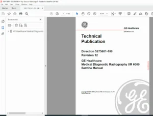
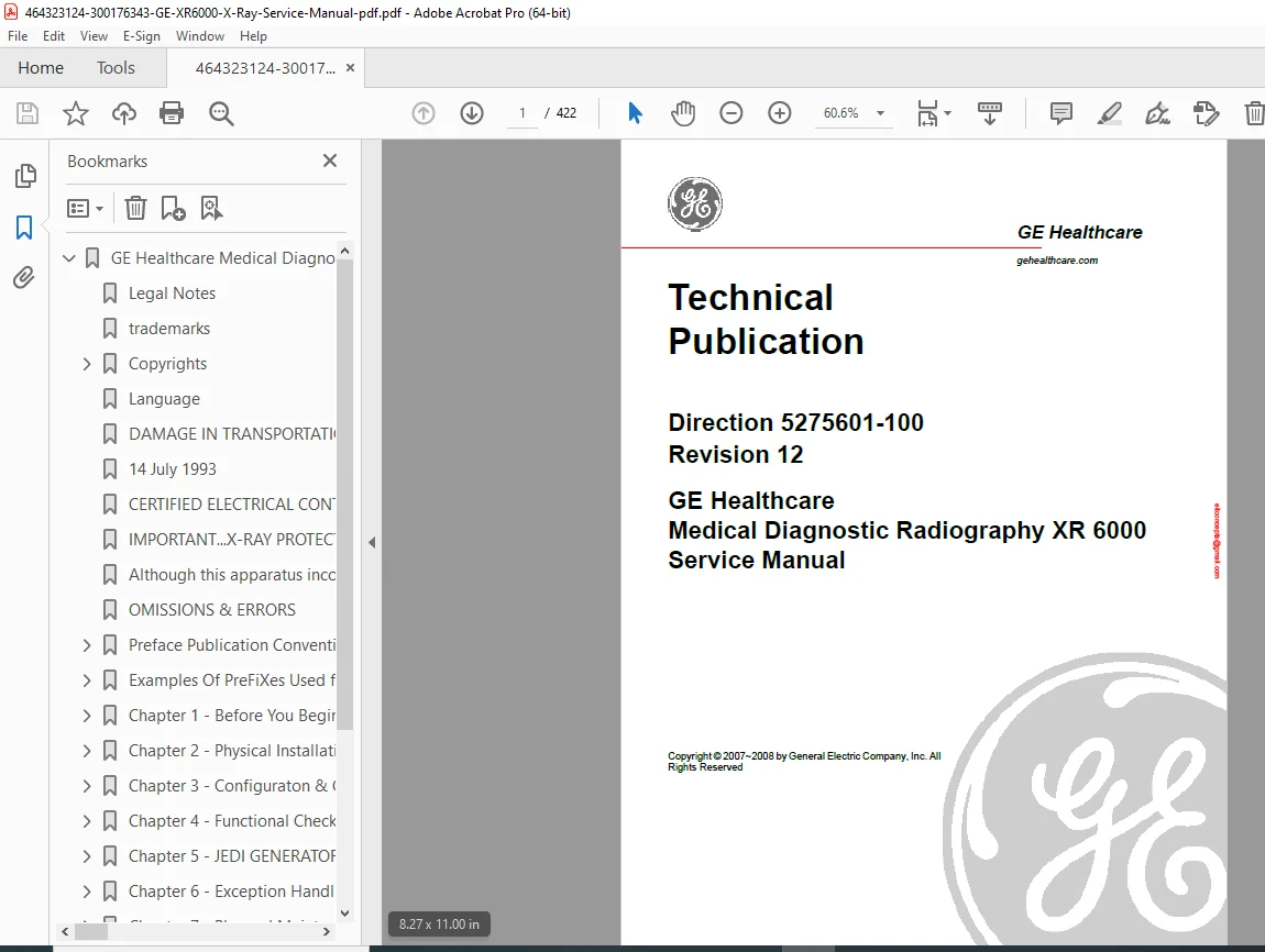
Download the official GE XR6000 service manual PDF for comprehensive installation, calibration, troubleshooting, and maintenance of GE Healthcare’s medical diagnostic radiography systems. This GE Healthcare X-ray repair guide download includes error codes, functional checks, renewal parts lists, and JEDI generator theory. Essential for technicians seeking a GE XR6000 radiography troubleshooting manual or XR6000 system configuration handbook. High-quality 422-page PDF with diagrams, procedures, and safety guidelines.
Description
GE XR6000 X-Ray System Service Manual PDF DOWNLOAD
Description
The GE XR6000 service manual PDF is an indispensable technical resource for servicing GE Healthcare’s XR 6000 medical diagnostic radiography systems. Covering installation, configuration, calibration, functional checks, error handling, planned maintenance, and renewal parts, this guide ensures precise diagnostics and repairs for X-ray equipment, including tube stands, collimators, consoles, and the JEDI generator. It provides detailed procedures for AEC calibration, performance verification, and component replacement, helping technicians maintain optimal system performance and compliance.
File Details:
- Manual Name: GE Healthcare Medical Diagnostic Radiography XR 6000 Service Manual
- Models Covered: XR 6000
- Year: 2007-2008
- Manual PDF Quality: High-resolution, searchable text with diagrams, tables, and illustrations
- No. of Pages: 422
The manual is structured with a comprehensive table of contents for easy navigation, extracted and categorized below using bullet points for main chapters and sub-bullets for sections and subsections. It includes safety information, system descriptions, and troubleshooting guides without an index or bookmarks in the provided excerpts.
Table of Contents:
- Preface
- Publication Conventions
- Section 1.0 Safety & Hazard Information
- Hazard Messages
- Text Format of Signal Words
- Symbols and Pictorials Used
- SPECIAL NOTICES
- X-ray Tube
- Power ON and OFF
- Electrical Type
- Electrical Current
- Collimator
- Ground
- Section 2.0 Publication Conventions
- General Paragraph and Character Styles
- Page Layout
- Computer Screen Output/Input Text Character Styles
- Buttons, Switches and Keyboard Inputs (Hard & Soft Keys)
- Section 1.0 Safety & Hazard Information
- Publication Conventions
- Chapter 1 – Before You Begin
- Section 1.0 Introduction
- Section 2.0 Objective and Scope of this Manual
- Pre-Installation Check
- Installation Plan
- Interconnection
- Presentation
- Section 3.0 On-Site Requirements
- EMC Requirements
- Tools and Test Equipment
- Documentation
- Audio and Visual
- Section 4.0 Description of System
- Chapter 2 – Physical Installation
- Section 1.0 System Installation Guide
- Section 2.0 Installation Checklist
- Section 3.0 Before You Begin
- Section 4.0 Integrated Table
- Radiography Table
- Unpacking and Positioning
- Installation
- Tube Stand
- Unpacking
- Installation
- X-Ray Tube
- Control Box and Collimator
- Counterweight
- Cassette Tray
- Ion Chamber and Grid (Optional)
- Install both Ion Chamber and Grid for system with standard Integrated table
- Install the Grid Only for system with standard Integrated table
- Electrical Connections
- Install Cabinet Tray
- Table Top Installation and Leveling
- Radiography Table
- Section 5.0 System Console
- Without Console Stand
- With Console Stand
- Section 6.0 Collimator Alignment
- Section 7.0 7.0DAP Meter Installation
- Section 8.0 Standard Wall Stand
- Unpacking
- Installation
- Cassette Tray
- Install both Ion Chamber and Grid (Optional)
- Install the Grid Only for standard wall stand
- Install the Ion Chamber Only for standard wall stand
- Counterweight
- Section 9.0 Final Cover Installation
- Install Standard Tube Stand Covers
- Install Front Cover
- Install Standard Wall Stand Covers
- Section 10.0 Labels and Rating Plates
- System Console
- Integrated Table
- Cabinet
- Wall Stand
- Section 11.0 Installation Checklist
- Section 12.0 Regulatory Tests and Final Steps
- AEC Tests
- AEC Maximum MAS
- Overview
- Procedure (50kV)
- AEC Minimum Exposure Time
- Overview
- Procedure
- Reproducibility Of Exposure
- Overview
- Procedure
- Calculation for Coefficient of Variation (C.V.)
- Final Installation and Administrative Tasks
- AEC Tests
- Chapter 3 – Configuration & Calibration
- Section 1.0 Configuration & Calibration List
- Section 2.0 Configuration & Calibration Contents
- System Configuration
- X-Ray Tube Seasoning
- Requirements
- Procedure
- Service Software User Guide
- Supplies
- Tools
- Prerequisites
- Personnel
- Time
- Procedure
- Loading service software on service laptop
- Using service software
- Typical screen description
- Tube Configuration
- Supplies
- Tools
- Safety Precautions
- Prerequisites
- Personnel
- Time
- Procedure
- Load software according to tube present in the installation
- Verify
- Receptor Programming
- Supplies
- Tools
- Safety Precautions
- Prerequisites
- Personnel
- Time
- Procedure
- Introduction
- Calling the subroutine
- Parameter selection
- Renard or normal scale for kV selection
- Date & Time
- Automatic AEC Calibration
- Supplies
- Tools
- Safety precautions
- Personnel
- Time
- Prerequisites
- PROCEDURE
- Development equipment
- Preliminary Remarks
- Principle
- KVEF Adjustment
- CR AEC Calibration
- Systems with CR Filming Only
- Program Generator with Default CR Parameters
- CR Dose Adjustment
- System with Film and CR Filming Combined
- Final Adjustment
- Disable Unused Film-Screen
- Perform Checksum
- Save Memory
- Systems with CR Filming Only
- Checksum Validation
- Supplies
- Tools
- Safety Precautions
- Prerequisites
- Personnel
- Time
- PROCEDURE
- Preliminary Remarks
- Checksum Validation
- Backup and Restore Database Parameters
- Supplies
- Safety Precautions
- Prerequisites
- Personnel
- Time
- Procedure
- CPU memory backup
- CPU memory restore
- Error messages
- Dosimetric Calibration
- Dose/DAP accuracy check procedure
- Dose/DAP accuracy maintenance
- Chapter 4 – Functional Checks
- Section 1.0 Introduction
- Section 2.0 Tools and Test Equipment
- Section 3.0 Operational Checks
- System Power Up
- Tube Assembly Operation
- Tube Stand Longitudinal Movement
- Tube Stand Rotation
- Tube Arm Vertical Movement
- X-Ray Tube Angulation
- X-Ray Ray Tilting
- Table Top Movement Checks
- Cassette Tray Movement
- Collimator Rotation
- Collimator Light Timer
- Wall Stand Carriage Vertical Movement
- Section 4.0 Performance Checks
- Console
- Accuracy of X-Ray Field and Light Field Alignment
- Requirements
- Test Method
- Alignment of Centers of X-Ray Field and Image Receptor
- Requirements
- Test Method
- Image Quality
- Test Method
- Tube Voltage Accuracy
- Tools
- Procedure
- Tube Current
- Requirements
- Procedure
- Exposure Time
- Requirements
- Procedure
- Exposure mAs
- Requirements
- Procedure
- Automatic Exposure Control (AEC) – Optional
- Table AEC
- Wall Stand AEC
- Collimator Light Timer
- Chapter 5 – JEDI GENERATOR THEORY AND FUNCTIONAL DESCRIPTION
- Section 1.0 Theory
- Glossary
- JEDI HIGH LEVEL BLOCK DIAGRAM
- Section 2.0 Theory Presentation
- Introduction
- Standard Features
- Applications
- Architecture
- A Kernel
- Options Depending on the Application
- A Packaging Architecture
- Auxiliaries Box
- Power Box
- AC/DC Box
- System Interface Box
- Optional Boxes
- Section 3.0 Technique Factors Measurement Criteria
- kV Accuracies
- mA Accuracies
- mAs Accuracies
- Exposure Time Accuracies
- Section 1.0 Theory
- Chapter 6 – Exception Handling And Error Codes
- Section 1.0 Exception Handling
- Diagnostics
- Power-On Diagnostic
- Live Diagnostics
- Error Code Structure
- Simplified Error Code Definition
- Generator Phase Definition
- Error Class Definition
- Error Code Definition
- Data Associated With The Error Code
- Number Of Occurrences
- Date & Time
- Section 2.0 Error Codes, Diagnostics & Troubleshooting
- Introduction
- Power On Diagnostics
- Error Code List
- Error Reporting
- Diagnostics
- Detailed Error Description & Troubleshooting Guide
- Errors
- Tube spits detection Errors (Code 30)
- Anode Rotation errors (Code 40)
- Filament Heater errors (Code 50)
- Exposure errors (Code 60)
- Power supply (Code 70)
- Hardware errors (Code 80)
- Application errors (Code 90)
- Communication errors (code 100)
- Thermal errors (code 110)
- Manipulation errors (code 120)
- Errors
- Warning Errors
- Other Failures
- Heating Function diagnostics
- Rotation Function diagnostics
- Inverter in Short Circuit Function diagnostics
- AEC diagnostics
- No Load HV diagnostics
- Inverter Gate Command diagnostics
- Section 3.0 Console Troubleshooting & Error Codes
- Error Codes
- Console Troubleshooting
- System Error (C01-0001)
- Memory Error on Console Control Board (C02-0001)
- Membrane Button Error (C02-1000)
- JEDI Communication Error (C03-0001)
- APR Random or All (C04-0001)
- No AEC Config (C04-0002)
- Overlimit (C04-0003)
- Phase Missing (C04-0004)
- Generator Error (C05-0001)
- Other Troubleshooting
- LED Unlit Failure
- Buzzer Failure
- LCD Display Failure
- LCD Display Faintness
- Power Un failure
- Section 4.0 PDU Troubleshooting
- PDU Troubleshooting
- No Console Power
- No EM Lock Power or No Collimator Power
- No Generator Power
- PDU Troubleshooting
- Section 1.0 Exception Handling
- Chapter 7 – Planned Maintenance
- Section 1.0 Preventive Maintenance Action List
- Section 2.0 Preventive Maintenance
- General Cleaning and Painting
- Supplies
- Tools
- Safety Precautions
- Prerequisites
- Personnel
- Time
- Procedure
- Visual Inspection
- Supplies
- Tools
- Safety Precautions
- Prerequisites
- Personnel
- Time
- Procedure
- Functional Checks
- Supplies
- Tools
- Safety Precautions
- Prerequisites
- Personnel
- Time
- Procedure
- Table Base Maintenance
- Supplies
- Tools
- Safety Precautions
- Prerequisites
- Personnel
- Time
- Procedure
- Patient Support Maintenance
- Supplies
- Tools
- Safety Precautions
- Prerequisites
- Personnel
- Time
- Procedure
- Cassette Tray Carriage Maintenance
- Supplies
- Tools
- Safety Precautions
- Prerequisites
- Personnel
- Time
- Procedure
- Tube Stand and Wall Stand Maintenance
- Supplies
- Tools
- Safety Precautions
- Prerequisites
- Personnel
- Time
- Procedure
- Generator Functional Checks
- Supplies
- Tools
- Safety Precautions
- Prerequisites
- Personnel
- Time
- Procedure
- Test exposure
- Post display initialization
- mA accuracy
- AEC functionality check (if existing)
- Record last error codes
- Record results on counters
- Check technique factors
- Tighten terminals and remove dust
- HV Cable and Sockets Regreasing
- Supplies
- Tools
- Safety Precautions
- Prerequisites
- Personnel
- Time
- Procedure
- Replace Generator NonVolatile Parameters RAM
- Supplies
- Tools
- Safety Precautions
- Prerequisites
- Personnel
- Time
- Procedure
- Remove and Replace the RAM
- Download Database
- General Cleaning and Painting
- Chapter 8 – Renewal Parts
- Section 1.0 Renewal Parts List
- Bearing kit 5196543, 5196544
- X-Ray Tube (5192454) / Collimator (5189248) Replacement
- Collimator Lamp (5136302) Replacement
- Rotundity Electricity Brake Assembly (5184986) Replacement
- Wall Stand Cassette Tray Spring Kit (5196542) Replacement
- Console Replacement
- Console Main Board Replacement
- Hand Switch Replacement
- TAV Board Replacement
- Table Top IF Board (5335073) Replacement
- Section 2.0 JEDI Generator Renewal Parts
- Introduction
- JEDI Generator Renewal Parts List
- FRU Information
- Jedi 50 R 1T Structure
- Renewal Parts
- Cables
- Section 3.0 JEDI Generator Disassembly/Reassembly
- Introduction
- Tools
- HV Tank, 1 Tube, 1-3 Phase
- Supplies
- Tools
- Safety Precautions
- Prerequisites
- Personnel
- Time
- Disassembly
- Reassembly
- Verify
- Inverter Mid-Power Assembly
- Supplies
- Tools
- Safety Precautions
- Prerequisites
- Personnel
- Time
- Section 1.0 Renewal Parts List
This GE XR6000 radiography troubleshooting manual is your go-to XR6000 system configuration handbook for efficient servicing and compliance in medical imaging environments.
Master X-ray system repairs with confidence—download this GE Healthcare X-ray repair guide PDF instantly and minimize downtime with expert-level instructions