GEHL BL 740 844 818 Backhoe Loader TLB Service Repair Manual PDF
Original price was: $95.00.$28.95Current price is: $28.95.
Official GEHL BL 740 / 844 / 818 backhoe loader (TLB) service manual by Manitou Group. This comprehensive GEHL TLB repair guide covers machine implements, electrical system, power-shift transmission, hydraulics, steering, rear axle, and brakes — complete with wiring schematics, hydraulic circuit diagrams, torque specifications, troubleshooting and testing & adjusting procedures for qualified heavy equipment technicians and fleet mechanics.
Description
GEHL BL 740 844 818 Backhoe Loader TLB Service Repair Manual PDF DOWNLOAD
Description
GEHL BL 740 / 844 / 818 Backhoe Loader — Official Service Manual
This is the official GEHL service and repair manual for the BL 740, BL 844, and BL 818 Backhoe Loader (TLB) series, published by Manitou Group (GEHL’s parent company). Spanning 263 pages across 8 major technical sections, this GEHL TLB workshop manual is the authoritative field reference for qualified heavy equipment technicians, fleet mechanics, and GEHL dealers responsible for maintaining, repairing, and overhauling these backhoe loaders to factory specifications.
📋 File Details
| Detail | Info |
|---|---|
| Manual Name | GEHL BL 740 / 844 / 818 Service Manual |
| Models Covered | GEHL BL 740, BL 844, BL 818 Backhoe Loaders (TLB) |
| Manufacturer | GEHL (Manitou Group) |
| Year | 2017 |
| PDF Quality | High-quality digital PDF — searchable & printable |
| Total Pages | 263 |
| File Size | ~21.5 MB |
📚 Full Table of Contents — Section by Section
Introduction — Safety & Torque Reference
- Important Safety Information — PPE requirements, mounting/dismounting, lifting, hot fluids, battery precautions, pressurized hydraulic systems, general hazard and crushing/cutting prevention
- Introduction to Torque — torque turn method, torque sequence (cross-pattern), fastener standards
- Metric (ISO) Fastener Torque Table — M1.6 through M36 (Nm values)
- English (SAE) Fastener Torque Table — 5/16″ through 2½” (Nm values)
- Machine Screws, Hex Button Head & Set Screw Torques
- Hose Clamp Torques — worm drive band type (7.9mm, 13.5mm, 15.9mm — new & reused hose values)
- Flare Fitting Torques — 37° flare nut specifications
Section 2 — Machine Systems (Implements)
- Introduction — loader beam design, quick attach system, multipurpose bucket and fork kit options
- Loader Attachment:
- Loader Bucket — Remove & Install (torque: 60 Nm)
- Loader Beam Cylinders — Remove & Install (30 Nm, 60 Nm, 230 Nm)
- Loader Beam — Remove & Install (48 Nm, 60 Nm, 67 Nm, 230 Nm)
- Backhoe Attachment:
- Backhoe Bucket — Remove & Install
- Boom/Dipper Assembly — Remove & Install
- Boom Swing Tower — Remove & Install
- Dipper Assembly — Remove & Install (30 Nm, 60 Nm)
- Stabilizer Hydraulic Cylinder — Remove & Install (with and without safety valve variants)
- Pedals & Levers:
- Backhoe Boom Latch Cable — Adjustment
- Loader Bucket Anti Rollback — Adjustment (gas strut 610mm, rod 723mm, pivot height 675mm)
- Stabilizer Wear Pad — Adjustment (colour-coded: 4.5mm Yellow, 5mm Black, 5.5mm Grey, 6mm Neutral, 6.5mm Red)
Section 3 — Electrical System
Component Removal & Installation:
- Starter Motor — Remove & Install (full torque table: solenoid main 6 Nm, cable fixing nut 9 Nm, through bolts 11 Nm, etc.)
- Windscreen Wiper Motor — Remove & Install
- Front & Rear Work Lamps — Remove, Install, Bulb Replace
- Front Head Light — Remove, Install, Bulb Replace (quartz halogen handling precautions)
- Rear Lights — Remove, Install, Bulb Replace
- Instrument Panel — Remove
- Forward/Reverse Switch — Remove & Install
- Alternator — Remove & Install
Testing & Adjusting:
- Charging Circuit Preliminary Testing
- Cable Continuity Test
- Voltage Regulator Test (target: 14.0–14.4V @ 1000 RPM)
- Voltage Drop Tests — insulated line (≤0.5V), earth line (≤0.25V)
- Alternator Output Test (70A @ 6000 RPM / 2168 engine RPM; regulation 13.6–14.4V)
- Battery Voltage Under Load Test (~10V minimum)
- Starter Motor Terminal Voltage Test
- Solenoid Contact Voltage Drop Test
- Earth Line, Contact Continuity & Voltage Drop Tests
- Battery Open Circuit & Diagnostic Test (≥12.5V pass threshold)
General Diagnostics Table — battery indicator symptoms, flat battery, internal shorts, overcharging, slack fan belt
Wiring Schematics (15 full circuits):
- Forward/Reverse, Engine Starting, Hazard/Indicator/Fuel Gauge/Brake, Wiper, Mast Lock, Un-loader, Front Head Lamp, Rear Work Lamp, Front Work Lamp, Horn, Cabin Lamp, Cabin Fan, Charging Circuit
Section 5 — Transmission (Power-Shift TLB)
Technical Specifications:
| Parameter | Value |
|---|---|
| Type | Power-shift, 4 forward / 4 reverse with hydraulic reverse |
| Dry Weight | 208 kg |
| Forward Ratios | 1st: 5.603 / 2nd: 3.48 / 3rd: 1.584 / 4th: 0.793 |
| Reverse Ratios | Identical to forward |
| Max Engine Power | 81 kW @ 2200 rpm |
| Max Input Speed | 3000 rpm |
| Torque Converter Stall Ratio | 3.01 |
| Suction Filter | 250 µm |
| Oil Pump Max Pressure | 16 bar |
| FWD/RVS Clutch Pressure | 11.0–13.0 bar |
| 4WD Pressure @ 900 RPM | 13.0–14.0 bar |
| 4WD PTO Max Engagement Speed Diff | 250 RPM |
| Scheduled Oil Volume | ~16 litres |
- Adhesive/Sealant Reference Chart — Loctite 510, 573, 539, 5205, 542, 270, 438, 405, 638, 496
- Transmission — Full Remove & Install (13-step procedure including cabin floor access, wiring harness disconnect, driveshaft, rear axle flange)
- Torque Converter — Remove & Install
- Transmission — Full Disassemble & Assemble
- Power-Shift Transmission System Operation
- Testing & Adjusting / Troubleshooting
Section 6 — Hydraulic System
Disassembly & Assembly:
- Hydraulic Pump — Remove, Disassemble, Inspect, Assemble
- Loader Control Valve — Remove, Install, Disassemble, Inspect, Assemble
- Backhoe Control Valve — Remove, Disassemble, Inspect, Assemble
- Mast Lock Piston Seals — Remove & Install
- Hydraulic Cylinder — Resealing procedures
Testing & Adjusting:
- Main Pressure Relief Valve — Test
- Hydraulic System Pressure — Release procedure
- Hydraulic Pump Flow — Test
- Hydraulic System — Flush
Troubleshooting — Hydraulic Cylinders
Hydraulic Schematic Symbols Guide — double-acting cylinders, check valves, fixed displacement motors, control spools, flow paths, and more
Section 7 — Steering System
- Steering Priority Valve — Remove, Disassemble, Inspect
- Steering Control Valve — Remove
- Steering Column — Remove & Install
- Steering Control Valve (Danfoss) — Disassemble, Inspect, Assemble
- Steering Control Valve (Ognibene) — Disassemble, Assemble
- Steering System Operation
- Steering System Pressure — Test
- Steering System — Troubleshooting
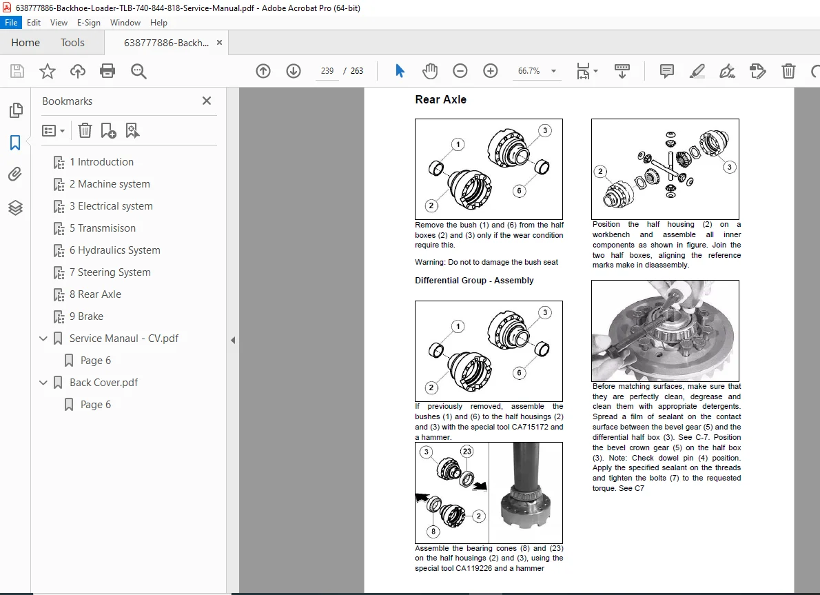
Section 8 — Rear Axle
Rear Axle Specifications:
| Parameter | Value |
|---|---|
| Axle Code | CA 146157 |
| Axle Model | 28.43 FR |
| Differential Type | Standard with hydraulic diff lock |
| Bevel Gear Ratio | 2.33:1 |
| Epicyclical Ratio | 6.923:1 |
| Total Ratio | 16.13:1 |
| Dry Weight | 413 kg |
| Input Rotation | Clockwise |
| Oil Specification | SAE 80W-90 EP |
| Differential Oil Capacity | 14.5 litres |
| Bevel Gear Set Backlash | 0.20–0.30 mm |
| Brake Type | Wet disc brake |
| Brake Discs per Side | 2 |
| Brake Counter Discs per Side | 3 |
| Nominal Brake Disc Thickness | 4.83 mm |
| Max Brake Disc Wear | 0.15 mm |
| Flange Type | End Yoke 1410 |
- Full Disassemble & Assemble procedures
- Testing & Adjusting
- Troubleshooting
Section 9 — Brake System
- Master Cylinder — Remove, Install, Disassemble, Inspect, Assemble
- Master Cylinder — System Operation (dual master cylinder with balance tube and compensator valves)
- Testing & Adjusting:
- Brake Pedal — Adjustment
- Brake System Air — Purge
- Parking Brake Control Cable — Adjustment
- Parking Brake — Adjustment
- Troubleshooting
💡 Why You Need This Manual
GEHL backhoe loader downtime on a job site costs thousands per day. This GEHL BL 740/844/818 TLB service manual delivers factory-level torque values, complete hydraulic circuit schematics, full 15-circuit electrical wiring diagrams, power-shift transmission disassembly sequences, and complete rear axle and brake rebuild procedures — all in one place. Purchase now, download instantly, and get your machine back to work today.