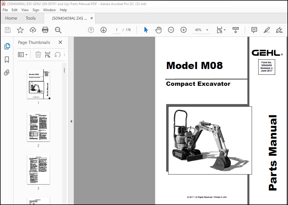
GEHL Compact Excavators M08 Parts Manual(50940490) – PDF DOWNLOAD
Original price was: $89.00.$26.95Current price is: $26.95.
GEHL Compact Excavators M08 Parts Manual(50940490) – PDF DOWNLOAD
Description
GEHL Compact Excavators M08 Parts Manual(50940490) – PDF DOWNLOAD
IMAGES PREVIEW OF THE MANUAL:
DESCRIPTION:
GEHL Compact Excavators M08 Parts Manual(50940490) – PDF DOWNLOAD
General
- MANITOU AMERICAS, INC. reserves the right to make changes or improvements in the design or construction of any part of the machine without incurring the obligation to install such changes on any previously delivered machines.
- This parts manual should not be used as a technical data reference; it uses simplified illustrations and does not detail servicing procedures.
- Internal engine components not shown in this manual are contained in a separate engine parts manual. The engine parts manual is contained in the documentation packet shipped with the machine, and is also available separately. Contact your dealer with any documentation requests.
- values are shown in Newton-meters, and are converted to foot-pounds by multiplying by 0.738.
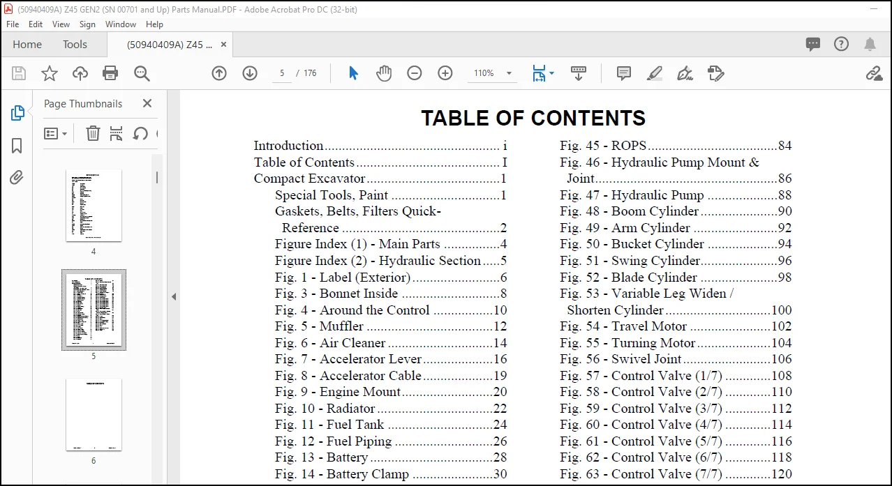
TABLE OF CONTENTS:
GEHL Compact Excavators M08 Parts Manual(50940490) – PDF DOWNLOAD
Introduction………………………………………….. i
Table of Contents………………………………….. I
Compact Excavator………………………………..1
Special Tools, Paint ………………………….1
Gaskets, Belts, Filters Quick-
Reference ………………………………………2
Figure Index (1) – Main Parts …………….4
Figure Index (2) – Hydraulic Section …..5
Fig. 1 – Label (Exterior)…………………….6
Fig. 3 – Bonnet Inside ……………………….8
Fig. 4 – Around the Control ……………..10
Fig. 5 – Muffler ………………………………12
Fig. 6 – Air Cleaner …………………………14
Fig. 7 – Accelerator Lever………………..16
Fig. 8 – Accelerator Cable………………..19
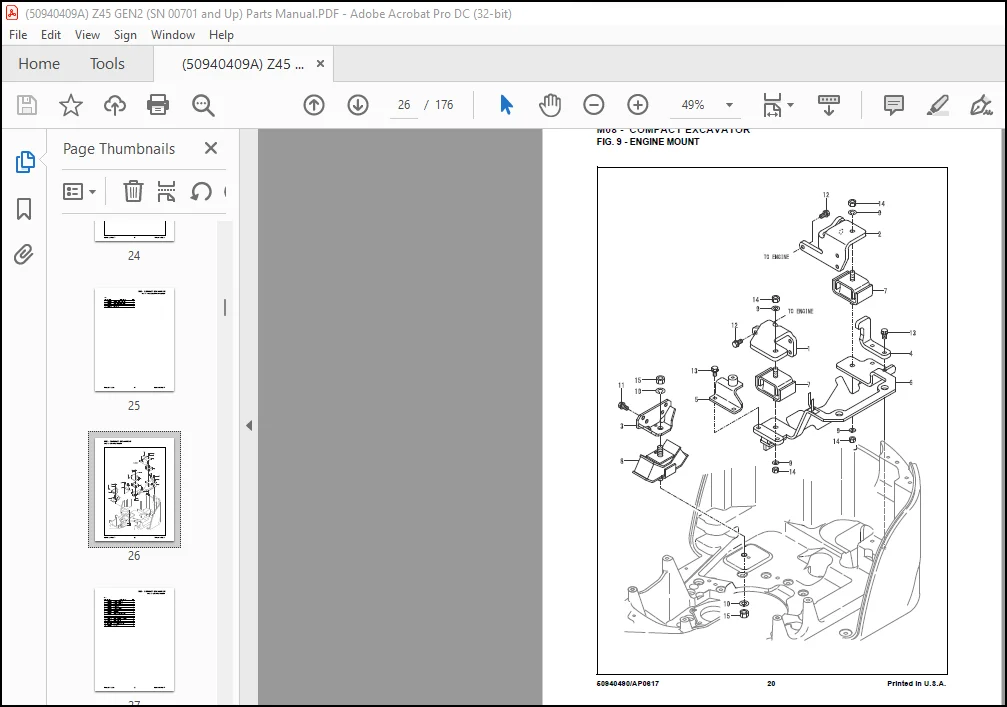
Fig. 9 – Engine Mount……………………..20
Fig. 10 – Radiator ……………………………22
Fig. 11 – Fuel Tank …………………………24
Fig. 12 – Fuel Piping ……………………….26
Fig. 13 – Battery ……………………………..28
Fig. 14 – Battery Clamp …………………..30
Fig. 15 – Wiring ……………………………..32
Fig. 16 – Equipment ………………………..34
Fig. 18 – Sprocket……………………………36
Fig. 19 – Idler …………………………………38
Fig. 20 – Track Roller ……………………..40
Fig. 21 – Crawler Adjust ………………….42
Fig. 22 – Crawler…………………………….44
Fig. 23 – Operation Lever (Right) ……..46
Fig. 24 – Operation Lever (Leftt) ………48
Fig. 25 – Blade Lever ………………………50
Fig. 26 – Travel Lever ……………………..52
Fig. 27 – Variable Leg Lever ……………54
Fig. 28 – Link …………………………………56
Fig. 29 – Swing Pedal………………………58
Fig. 30 – P.T.O. Pedal ……………………..60
Fig. 31 – Stopper …………………………….62
Fig. 32 – Link Stand ………………………..64
Fig. 34 – Travel Frame …………………….66
Fig. 35 – Turning Frame…………………..68
Fig. 37 – Turning Bearing ………………..70
Fig. 38 – Turning Lock Lever …………..72
Fig. 39 – Cover (Travel Frame)…………74
Fig. 40 – Step………………………………….76
Fig. 41 – Seat ………………………………….78
Fig. 42 – Seat Belt …………………………..80
Fig. 43 – Bonnet ……………………………..82
Fig. 45 – ROPS……………………………….84
Fig. 46 – Hydraulic Pump Mount &
Joint…………………………………………….86
Fig. 47 – Hydraulic Pump ………………..88
Fig. 48 – Boom Cylinder ………………….90
Fig. 49 – Arm Cylinder ……………………92
Fig. 50 – Bucket Cylinder ………………..94
Fig. 51 – Swing Cylinder………………….96
Fig. 52 – Blade Cylinder ………………….98
Fig. 53 – Variable Leg Widen /
Shorten Cylinder …………………………100
Fig. 54 – Travel Motor …………………..102
Fig. 55 – Turning Motor…………………104
Fig. 56 – Swivel Joint…………………….106
Fig. 57 – Control Valve (1/7) ………….108
Fig. 58 – Control Valve (2/7) ………….110
Fig. 59 – Control Valve (3/7) ………….112
Fig. 60 – Control Valve (4/7) ………….114
Fig. 61 – Control Valve (5/7) ………….116
Fig. 62 – Control Valve (6/7) ………….118
Fig. 63 – Control Valve (7/7) ………….120
Fig. 64 – Hyd. Oil Tank………………….122
Fig. 65 – Tank – Pump – Control
Valve…………………………………………124
Fig. 66 – Control Valve – Turning
Motor & Swing Cylinder ……………..126
Fig. 67 – Control Valve – Swivel
Joint…………………………………………..128
Fig. 68 – Return…………………………….130
Fig. 69 – Travel Frame …………………..132
Fig. 70 – Boom ……………………………..134
Fig. 72 – P.T.O. (Frame End)………….136
Fig. 73 – P.T.O. (Boom End) ………….138
Fig. 75 – Greasing …………………………140
Fig. 76 – Boom Bracket………………….142
Fig. 78 – Boom ……………………………..144
Fig. 80 – Arm ……………………………….146
Fig. 82 – Bucket Arm & Link …………148
Fig. 84 – Bucket Pin ………………………150
Fig. 85 – Blade ……………………………..152
Need help? Contact: [email protected]
PLEASE NOTE:
- This is the same manual used by the dealers to diagnose and troubleshoot your vehicle
- You will be directed to the download page as soon as the purchase is completed. The whole payment and downloading process will take anywhere