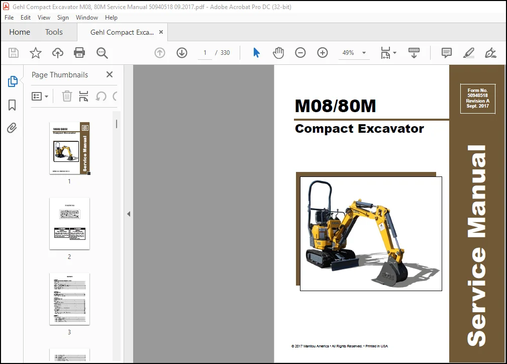
Gehl M08 80M Compact Excavator Service Manual 50940518 – PDF DOWNLOAD
Original price was: $86.95.$28.95Current price is: $28.95.
Gehl M08 80M Compact Excavator Service Manual 50940518 – PDF DOWNLOAD
Description
Gehl M08 80M Compact Excavator Service Manual 50940518 – PDF DOWNLOAD
FILE DETAILS:
Gehl M08 80M Compact Excavator Service Manual 50940518 – PDF DOWNLOAD
Language : English
Pages : 330
Downloadable : Yes
File Type : PDF
Size: 11.5 MB
IMAGES PREVIEW OF THE MANUAL:
DESCRIPTION:
Gehl M08 80M Compact Excavator Service Manual 50940518 – PDF DOWNLOAD
1-2 Safety Precautions:
(1) Never attempt servicing while engine is running or immediately after stopping operation.
(2) Wear work cloths, safety shoes and helmet.
(3) Check the equipment and tools before use. Especially, be sure to check the crane, lifting equipment and tools.
(4) When working together with other persons, allocate everyone’s share of job, arrange the signals and act in
concert with the other persons.
(5) The operation of the crane and slinging work must be performed by qualified persons.
(6) Do not enter or pass under the raised load.
(7) Lift and support the massive parts by crane before removing the installation bolts.
(8) Disconnect cables from battery before repairing the electric system.
(9) Remove the battery when welding the machine.
1-3 Preparations:
(1) Check the service record of the machine. (That is, check how many months or hours the machine has been
used since the preceding overhaul, what was the trouble then and what parts were replaced.)
(2) Have all servicing tools ready, i.e., tools, measuring devices (which have received periodic maintenance),
containers, oil & grease, etc.
(3) Have the service literature (operation manual, parts catalog, etc.) ready.
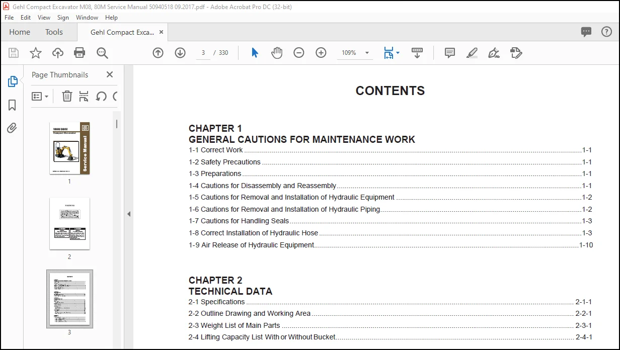
TABLE OF CONTENTS:
Gehl M08 80M Compact Excavator Service Manual 50940518 – PDF DOWNLOAD
GENERAL CAUTIONS FOR MAINTENANCE WORK
1-1 Correct Work
1-2 Safety Precautions
1-3 Preparations
1-4 Cautions for Disassembiy and Reassembly
1-5 Cautions for Removal and Installation of Hydraulic Equipment
1-6 Cautions for Removal and Installation of Hydraulic Piping
1-7 Cautions for Handling Seals
1-8 Correct installation Of Hydraulic Hose
1-9 Air Release of Hydraulic EqUIpment
CHAPTER 2
TECHNICAL DATA
2-1 SpeCIficatIons
2-2 Outline Drawing and Working Area
2-3 Weight List of Main Parts
2-4 Lifting Capacity List With orWithoutBucket
CHAPTER 3
SERVICE STANDARDS
3-1 Machine Performance
3-2 Engine
3-3 Undercarriage
3-3-1 Rubber Crawler Specifications
3-4 Controls
3-5 Hydraulic EqUIpment
3-5-1 Hydraulic Cylinders
3-6 Implement
3-6-1 Front Attachments
3-6-2 Variable Track Gauge Type and Blade Moving Device
3-6-3 Bucket Teeth
3-7-1 MachIne
3-7-2 Engine
3-7-3 Tightening Torque for General Bolts and Nuts (Machine)
3-7-4 Hydraulic Hose Joint
4—1-1 Removing the Nozzle and Glow Plug
4—1-2 Removing the Cylinder Head Cover
4-1-3 Removing the Oil PIpe
4-1-4 Removing the Water Pump Assembly
4-1-5 Removing the Rocker Arm and Push Rods
4-1-6 Removing the Exhaust ManIfoId
4-1-7 Removing the Cylinder Head
4-1-8 Removing the Tappets
4-1-9 Removing the Injection Pump Assembly
4-1-10 Removing the Crankshaft Pulley
4-1-11 Removing the Timing Gear Case Assembly
4-1-12 Removing the Idle Gear and Oil Pump Assembly
4-1-13 Removing the Camshaft Assembly
4-1-14 Removing the Suction Filter and Pipe
4-1-15 Removing the Connecting Rods and Pistons
4-1-16 Removing the Crankshaft Assembly
4-2 Disassembiy, Inspection and Reassembiy of Main Component Parts-
4-2-1 Cylinder Head
4-2-2 Rocker Amt
4-2-3 Cylinder Block
4-2—4 Piston and Piston Rings
4-2-5 Connecting Rod
4-2-6 Connecting Rod Metal
4-2-7 Bearing Holder
4-2-8 Crankshaft Beanng
4-2-9 Crankshaft
4-2-10 Timing Gears and Camshaft Assembly
4-2-11 Lubrication Oil Pump
4-2-12 Thermostat
4-2-13 Nozzle and Holder Assembly
4-2-14 Flywheel and Ring Gear
4-3 Reassembiy of Engine
4-3-1 Crankshaft and Bearing Holder Assembly
4-3-2 Oil Seal and Flywheel Cover (Rear Plate)
4-3-3 Flywheel
4-3—4 Pistons and Connecting Rods
4-2-5 Connecting Rod
4-2-6 Connecting Rod Metal
4-2—7 Bearing Holder
4-2-8 Crankshaft Bearing
4-2-9 Crankshaft
4-2-10 Timing Gears and Camshaft Assembly
4-2-11 Lubrication Oil Pump
4-2-12 Thermostat
4-2-13 Nozzle and Holder Assembly
4-2—14 Flywheel and Ring Gear
4-3 Reassembiy of Engine
4-3-1 Crankshaft and Bearing Holder Assembly
4-3-2 Oil Seal and Flywheel Cover (Rear P|ate)
4-3-3 Flywheel
4-3-4 Pistons and Connecting Rods
4-3-5 Suction Pipe and Suction Filter
4-3-6 Oil Pan and Front Plate
4-3-7 Camshaft Assembly and Plate
4-3-8 Idle Gear and Oil Pump Assembly
4-3-9 Timing Gear Case
4-3—10 Crankshaft Pulley
4-3-11 Injection Pump Assembly
4-3-12 Oil filter and Oil Pipe
4-3-13 Tappets
4-3-14 Cylinder Head Assembly and Cylinder Head Gasket.-
4-3-15 Caps, Push Rods and Rocker Amt Assembly
4-3-16 Adjusting the valve Clearance
4-3-17 Cylinder Head Cover
4-3-18 Water Pump Assembly
4-3-19 Oil Pressure Switch
4-3-20 Nozzle and Holder Assembly
4-3-21 Return Pipes and Injection Pipes
4-3-22 V-beit
4-4 Electrical Equipment
4-4-1 Starter Motor
4-4-2 Alternator
4-4-3 Glow Plug
4-5 Troubleshooting
4-6 Electric Control System
4—6—1 Parts Name and POSItIon
4—6-2 Electric Unit
4—6—3 Troubleshooting
4-6-4 Service
CHAPTER 5
HYDRAULIC SYSTEM
5-1 Outline
5-1-1 Control Valve Operation
5-2 Hydraulic Circuit Schematic
5-3 Circuit Operation
5-3-1 Boom
5-3-3 Bucket
5-3-5 Boom Swing
5-3-6 Blade
5-3-7 Travel
5-3-8 Simultaneous Operation of Travel and Biade………..
5-3-9 Hydraulic P.T.O.
5-3-10 Simultaneous Operation of Boom Up and Bucket.
5-3-11 Track Gauge Change
5-4 Pressure Adjustment
5-4-1 Relief Valves
5-4-2 Swing Combination Valve (Brake Valve)…
CHAPTER?—
ADJUSTMENT AND REPAIR
7-1 Electrical Equipment of Machine
7—1-1 Parts Layout of Electrical Equipment
7—1-2 Monitor and Alarm Systems
7—1-3 Wiring DIagram
7—1-4 Circuit Description of Engine Start and Stop
7—1—5 Circuit Description of Battery Charging
7-1-6 Removal and Reinstallation of Engine
7-1-7 Removal and Reinstallation of Starter motor
7-1-8 Removal and Reinstallation of Engine ECU
7-2 Undercarriage
7-2—1 Outline
7-2—2 Points of Reassembiy
7-2—3 Disassembly and Reassembiy of Idler
7-2—4 Disassembly and Reassembiy of Track Roller
7-3 Controls
7-3-1 Control Train
7-3-2 Removal and Reinstallation of Control Levers
7-3-3 Adjustment of Control Levers
7-3-4 Adjustment of Travel Levers
7-3—5 Adjustment of P.T.O. Pedal
7-3-6 Adjustment of Boom Swing Pedal
7-3-7 Adjustment of Blade Lever
7-3-8 Adjustment of Accelerator Lever (Adjustment of Engine Idling Speed).
7-4 Swing Bearing
7-4-1 Removal and Reinstallation of Swing Bearing
7-5 Hydraulic EqUIpment
7-5-1 Removal and Reinstallation of Hydraulic Pump
7—5—2 Removal and Reinstallation of Control Valve
7-5-3 Removal and Reinstallation of Swing Motor
7-5-4 Removal and Reinstallation of Swivel JOInt
7-5-5 Disassembly and Reassembiy of Swivel Joint
7-5-6 Disassembly and Reassembiy of Hydraulic Cylinders
7-5-7 Removal and Reinstallation of Hydraulic Oil Tank
7-5-8 Removal and Reinstallation of Track Gauge Change Cylinder…
7-5-9 Piping Layout
7-6-1 Removal and Reinstallation of ROPS bar
7-7-1 Removal and Reinstallation of Work Implements
CHAPTER 9
10-1-1 Natural Release of Bucket
10-1-2 Discontinuous Arm Movement
10-1-3 Drifting of Upperstmcture on Quick Travel Operation
10-1-4 Thermal Shock of Travel Motor
10-1-5 Fluctuation in Oil Level of Hydraulic Oil Tank Due to Temperature Change.
10-2-1 Machine and Engine
10-2-2 Electrical Equipment on Panel
Need help? Contact: [email protected]
https://vimeo.com/801161907
PLEASE NOTE:
- This is the same manual used by the DEALERSHIPS to SERVICE your vehicle.
- The manual can be all yours – Once payment is complete, you will be taken to the download page from where you can download the manual. All in 2-5 minutes time!!
- Need any other service / repair / parts manual, please feel free to contact us at heydownloadss @gmail.com . We may surprise you with a nice offer
S.V