Gehl R135 & GEN:2, R150 & GEN:2, R165 Mustang 1350R & NXT2, 1500R & NXT2, 1650R Skid Steer Loader Service Manual 50940256 – PDF DOWNLOAD
Original price was: $86.95.$28.95Current price is: $28.95.
Gehl R135 & GEN:2, R150 & GEN:2, R165 Mustang 1350R & NXT2, 1500R & NXT2, 1650R Skid Steer Loader Service Manual 50940256 – PDF DOWNLOAD
Description
Gehl R135 & GEN:2, R150 & GEN:2, R165 Mustang 1350R & NXT2, 1500R & NXT2, 1650R Skid Steer Loader Service Manual 50940256 – PDF DOWNLOAD
FILE DETAILS:
Gehl R135 & GEN:2, R150 & GEN:2, R165 Mustang 1350R & NXT2, 1500R & NXT2, 1650R Skid Steer Loader Service Manual 50940256 – PDF DOWNLOAD
Language : English
Pages : 366
Downloadable : Yes
File Type : PDF
Size: 257 MB
IMAGES PREVIEW OF THE MANUAL:
DESCRIPTION:
Gehl R135 & GEN:2, R150 & GEN:2, R165 Mustang 1350R & NXT2, 1500R & NXT2, 1650R Skid Steer Loader Service Manual 50940256 – PDF DOWNLOAD
INTRODUCTION:
Contents and Use of this Manual :
This manual provides information about the safe and proper operation, maintenance and service procedures for the machine. Major points of safe operation, maintenance and service are detailed in the Safety chapter of this manual. This manual also includes general troubleshooting and specification information about the machine.
- Follow the instructions in the Safety, Operation and Maintenance chapters concerning accident prevention regulations, safety and occupational regulations, and machine and traffic regulations. Manitou Americas is not liable for damage resulting from the failure to follow these regulations.
- It is the owner’s or employer’s responsibility to fully instruct each operator in the proper and safe operation and maintenance of the machine. A storage location is provided inside the operator’s compartment for storing the Operator’s Manual. After using the manual, return it to the storage container. Replace the operator’s manual promptly if it becomes damaged, lost or stolen.
TABLE OF CONTENTS:
Gehl R135 & GEN:2, R150 & GEN:2, R165 Mustang 1350R & NXT2, 1500R & NXT2, 1650R Skid Steer Loader Service Manual 50940256 – PDF DOWNLOAD
Introduction……………………………………………………………………………………………………………….. 11
Safety Symbol and Signal Words……………………………………………………………………………………………. 11
Signal Words………………………………………………………………………………………………………… 11
Contents and Use of this Manual…………………………………………………………………………………………… 11
Machine Orientation……………………………………………………………………………………………………… 12
Proper Machine Use………………………………………………………………………………………………………. 13
Service and Registration…………………………………………………………………………………………………. 13
Model and Serial Numbers……………………………………………………………………………………………… 13
Fields of Application……………………………………………………………………………………………………. 14
Using Attachments……………………………………………………………………………………………………….. 14
Vibration Information……………………………………………………………………………………………………. 16
Vibration Measurement and Actions……………………………………………………………………………………… 16
Vibration Levels…………………………………………………………………………………………………….. 17
Fire Extinguisher Location……………………………………………………………………………………………….. 17
Manufacturer Information…………………………………………………………………………………………………. 17
Indicator and Operation Symbols…………………………………………………………………………………………… 18
Safety…………………………………………………………………………………………………………………….. 19
Safety Symbol and Signal Words……………………………………………………………………………………………. 19
Safety Alert Symbol………………………………………………………………………………………………….. 19
Mandatory Safety Shutdown Procedure……………………………………………………………………………………….. 20
Safety Reminders………………………………………………………………………………………………………… 20
Before Starting……………………………………………………………………………………………………… 20
Additional Safety Equipment…………………………………………………………………………………………… 22
During Operation…………………………………………………………………………………………………….. 22
Applications with Load-Handling Devices………………………………………………………………………………… 24
Parking the Machine………………………………………………………………………………………………….. 24
Electrical Energy……………………………………………………………………………………………………. 25
Maintenance…………………………………………………………………………………………………………. 25
Battery Hazards……………………………………………………………………………………………………… 27
Fire Hazards………………………………………………………………………………………………………… 27
Crystalline Silica Exposure………………………………………………………………………………………………. 28
Transporting the Machine……………………………………………………………………………………………… 28
Lifting the Machine with a Crane………………………………………………………………………………………. 28
Loading and Transporting the Machine…………………………………………………………………………………… 29
Safety Decals…………………………………………………………………………………………………………… 29
New Decal Application………………………………………………………………………………………………… 29
Safety Equipment……………………………………………………………………………………………………………. 31
Guards and Shields………………………………………………………………………………………………………. 31
Operator’s Position……………………………………………………………………………………………………… 31
Operator’s Seat……………………………………………………………………………………………………… 31
Seat suspension……………………………………………………………………………………………………… 32
Seat Belt…………………………………………………………………………………………………………… 32
Fastening/Unfastening the Seat Belt………………………………………………………………………………… 32
Upper Torso Restraint (Option)………………………………………………………………………………………… 33
Operator Restraint Bar……………………………………………………………………………………………….. 33
Safety Interlock System (Hydraloc™)……………………………………………………………………………………….. 34
Safety Interlock System Test………………………………………………………………………………………….. 34
Seat Switch Test…………………………………………………………………………………………………. 34
Restraint Bar Test……………………………………………………………………………………………….. 34
Parking Brake…………………………………………………………………………………………………………… 34
ROPS/FOPS………………………………………………………………………………………………………………. 34
Rear Window Emergency Exit……………………………………………………………………………………………….. 35
Rear Window Emergency Exit Removal/ Installation………………………………………………………………………… 35
Removal…………………………………………………………………………………………………………. 35
Installation…………………………………………………………………………………………………….. 36
Lift Arm Support………………………………………………………………………………………………………… 37
Engage Lift Arm Support………………………………………………………………………………………………. 37
Disengage Lift Arm Support……………………………………………………………………………………………. 38
Battery Disconnect Switch (Option)………………………………………………………………………………………… 38
Indicators and Controls……………………………………………………………………………………………………… 39
Control Keypad………………………………………………………………………………………………………….. 40
Control Keypad Indicators…………………………………………………………………………………………….. 40
Control Keypad Buttons……………………………………………………………………………………………….. 42
Accessory Keypad Indicators/Buttons……………………………………………………………………………………….. 43
Optional Lights/Lockout Keypad Indicators/Buttons…………………………………………………………………………… 44
Information Center Electronic Display……………………………………………………………………………………… 45
Information Center Electronic Display Symbols…………………………………………………………………………… 46
Information Center Electronic Display Screens…………………………………………………………………………… 47
Controls……………………………………………………………………………………………………………….. 51
Ignition Keyswitch…………………………………………………………………………………………………… 51
Throttle Controls……………………………………………………………………………………………………. 51
Travel Drive, Lift and Tilt Controls…………………………………………………………………………………… 53
T-Bar Controls…………………………………………………………………………………………………… 53
Joystick Controls………………………………………………………………………………………………… 55
Hand and Foot Controls……………………………………………………………………………………………. 58
Two-Speed Drive (Option)…………………………………………………………………………………………………. 61
Lift Arm Float………………………………………………………………………………………………………….. 62
Hydraglide™ Ride Control System…………………………………………………………………………………………… 63
Beacon/Position/Work Lights………………………………………………………………………………………………. 64
HVAC (Optional)…………………………………………………………………………………………………………. 64
Windshield Wiper/Washer………………………………………………………………………………………………….. 65
Dome Light……………………………………………………………………………………………………………… 65
Accessory Plug………………………………………………………………………………………………………….. 66
Battery Disconnect Switch (Option)………………………………………………………………………………………… 66
Attachment Mounting……………………………………………………………………………………………………… 66
All-Tach® Hitch……………………………………………………………………………………………………… 66
Power-A-Tach® System…………………………………………………………………………………………………. 67
Auxiliary Hydraulic System……………………………………………………………………………………………….. 68
Auxiliary Hydraulic Couplers………………………………………………………………………………………….. 68
Auxiliary Hydraulic Control…………………………………………………………………………………………… 68
Operation………………………………………………………………………………………………………………….. 71
Before Starting the Engine……………………………………………………………………………………………….. 71
Operational Checks…………………………………………………………………………………………………… 71
Pre-Start Checks…………………………………………………………………………………………………. 71
Checks During Operation…………………………………………………………………………………………… 72
Cab Entry and Exit…………………………………………………………………………………………………… 72
Opening/Closing the Cab Door (Option)………………………………………………………………………………. 72
Starting the Engine……………………………………………………………………………………………………… 73
Cold-Starting……………………………………………………………………………………………………….. 74
After Starting………………………………………………………………………………………………………. 75
Warm Up…………………………………………………………………………………………………………….. 75
Run-In Period…………………………………………………………………………………………………………… 75
Stopping the Machine…………………………………………………………………………………………………….. 76
Engine Stalling…………………………………………………………………………………………………………. 76
Parking the Machine……………………………………………………………………………………………………… 76
Brake Release Operation (Option)………………………………………………………………………………………….. 76
Jump-starting…………………………………………………………………………………………………………… 77
Travel Drive Operation…………………………………………………………………………………………………… 79
Two-Speed Drive (Option)……………………………………………………………………………………………… 79
Driving on an Incline………………………………………………………………………………………………… 79
Driving over Rough Terrain……………………………………………………………………………………………. 79
Transport on Public Roads………………………………………………………………………………………………… 80
Transport Hydraulics Lock-out (Option)…………………………………………………………………………………. 80
Lift Arm Operation………………………………………………………………………………………………………. 80
Attachment Transport Position…………………………………………………………………………………………. 80
Lift Arm Float………………………………………………………………………………………………………. 81
Hydraglide™ Ride Control System……………………………………………………………………………………….. 81
Changing Attachments…………………………………………………………………………………………………….. 82
Connecting Attachments……………………………………………………………………………………………….. 82
Disconnecting Attachments…………………………………………………………………………………………….. 84
Connecting Auxiliary Hydraulic Couplings……………………………………………………………………………….. 84
Disconnecting Auxiliary Hydraulic Couplings…………………………………………………………………………….. 85
Self-Leveling (Option)…………………………………………………………………………………………………… 86
Self-Leveling Cancel…………………………………………………………………………………………………. 86
Using Buckets…………………………………………………………………………………………………………… 86
Using Pallet Forks………………………………………………………………………………………………………. 86
Loading and Transporting the Machine on a Transport Vehicle………………………………………………………………….. 87
Towing…………………………………………………………………………………………………………………. 88
Lifting the Machine Using a Crane or Hoist…………………………………………………………………………………. 89
Diesel Particulate Filter (DPF) Regeneration Procedures (DPF Models)………………………………………………………….. 90
Reset Regeneration…………………………………………………………………………………………………… 90
Reset Regeneration Inhibit………………………………………………………………………………………… 91
Stationary Regeneration………………………………………………………………………………………………. 91
Forcing Stationary Regeneration……………………………………………………………………………………….. 93
DPF Maintenance……………………………………………………………………………………………………… 93
Maintenance………………………………………………………………………………………………………………… 95
Maintenance Schedules……………………………………………………………………………………………………. 97
Maintenance Log…………………………………………………………………………………………………………. 99
General Lubrication………………………………………………………………………………………………………102
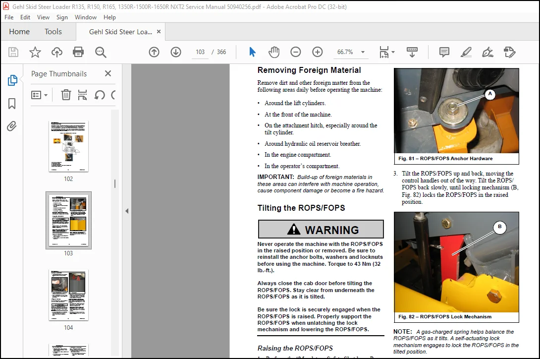
Removing Foreign Material…………………………………………………………………………………………………103
Tilting the ROPS/FOPS…………………………………………………………………………………………………….103
Raising the ROPS/FOPS…………………………………………………………………………………………………103
Lowering the ROPS/FOPS………………………………………………………………………………………………..104
Lifting the Machine………………………………………………………………………………………………………104
Lowering the Machine………………………………………………………………………………………………….105
Engine Maintenance……………………………………………………………………………………………………….105
Engine Access………………………………………………………………………………………………………..105
Engine Mounting Hardware Inspection…………………………………………………………………………………….105
Checking Engine Oil Level……………………………………………………………………………………………..106
Changing Engine Oil and Filter…………………………………………………………………………………………106
Fuel System Maintenance…………………………………………………………………………………………………..107
Adding Fuel………………………………………………………………………………………………………….108
Water Separator Maintenance……………………………………………………………………………………………108
Changing Water Separator Filter………………………………………………………………………………………..109
Changing Fuel Filter………………………………………………………………………………………………….110
Fuel Tank Drain………………………………………………………………………………………………………111
Engine Air Cleaner……………………………………………………………………………………………………….112
Changing Air Filter Elements…………………………………………………………………………………………..112
DPF Service (DPF Models)………………………………………………………………………………………………….113
V-Belt Maintenance……………………………………………………………………………………………………….113
Cooling System…………………………………………………………………………………………………………..114
Checking Coolant Level………………………………………………………………………………………………..114
Cleaning Radiator Fins………………………………………………………………………………………………..114
Draining/Flushing Cooling System……………………………………………………………………………………….114
Hydraulic System…………………………………………………………………………………………………………116
Checking Hydraulic Oil Level…………………………………………………………………………………………..116
Changing Hydraulic Oil Filter………………………………………………………………………………………….117
Changing Hydraulic Oil………………………………………………………………………………………………..117
Cab Heater Filter Replacement……………………………………………………………………………………………..118
Hydraulic Hose Maintenance………………………………………………………………………………………………..119
Chaincases………………………………………………………………………………………………………………120
Drive Motors…………………………………………………………………………………………………………120
Checking and Adding Chaincase Oil………………………………………………………………………………………120
Changing Chaincase Oil………………………………………………………………………………………………..120
Drive Chain Tension…………………………………………………………………………………………………..120
Checking Chain Tension…………………………………………………………………………………………….120
Adjusting Chain Tension……………………………………………………………………………………………120
Drive Chain Replacement……………………………………………………………………………………………….120
Seat and Restraint Bar Switches……………………………………………………………………………………………121
Bucket Cutting Edge………………………………………………………………………………………………………121
Wheel Nuts………………………………………………………………………………………………………………121
Tires…………………………………………………………………………………………………………………..121
Mounting Tires……………………………………………………………………………………………………….121
Checking Tire Pressure………………………………………………………………………………………………..121
Electrical System………………………………………………………………………………………………………..122
Fuses, Relays and Diodes………………………………………………………………………………………………122
Fuse/Relay/Diode Locations…………………………………………………………………………………………123
Battery……………………………………………………………………………………………………………..125
Windshield Washer Reservoir……………………………………………………………………………………………….125
Long-Term Storage………………………………………………………………………………………………………..125
Before Storage……………………………………………………………………………………………………….125
After Storage………………………………………………………………………………………………………..126
Final Shutdown / Decommissioning…………………………………………………………………………………………..126
Before Disposal………………………………………………………………………………………………………126
Machine Disposal……………………………………………………………………………………………………..127
Hydrostatic System…………………………………………………………………………………………………………..129
Introduction…………………………………………………………………………………………………………….129
Charge Pressure Test and Adjustment………………………………………………………………………………………..135
Preparation………………………………………………………………………………………………………….135
Test Procedure……………………………………………………………………………………………………….135
Hydrostatic Pump Relief Valves…………………………………………………………………………………………….136
Hydrostatic Pump Removal and Installation…………………………………………………………………………………..136
Removal……………………………………………………………………………………………………………..136
Installation…………………………………………………………………………………………………………137
Hydrostatic Pump Drive Coupling Removal and Installation……………………………………………………………………..138
Installation…………………………………………………………………………………………………………138
Drive System………………………………………………………………………………………………………………..139
Introduction…………………………………………………………………………………………………………….139
Drive Chain Adjustment……………………………………………………………………………………………………143
Models R165/1650R, R150/1500R, R135 (SN FOE193365 and Up), 1350R (SN DOE187213 and Up)……………………………………….143
Axle Housing Assembly Removal and Installation………………………………………………………………………………144
Axle Housing Removal………………………………………………………………………………………………….144
Models R165/1650R, R150/1500R, R135 (SN FOE193365 and Up), 1350R (SN DOE187213 and Up)……………………………………144
Axle Housing Installation……………………………………………………………………………………………..145
Models R165/1650R, R150/1500R, R135 (SN FOE193365 and Up), 1350R (SN DOE187213 and Up)……………………………………145
Axle Installation…………………………………………………………………………………………………….146
R135 (SN FOE193364 and Before), 1350R (SN DOE187212 and Before)………………………………………………………..146
Axle and Wheel Bearing Disassembly/Assembly…………………………………………………………………………………147
Models R165/1650R, R150/1500R, R135 (SN FOE193365 and Up), 1350R (SN DOE187213 and Up)……………………………………….147
Disassembly………………………………………………………………………………………………………….147
Assembly…………………………………………………………………………………………………………….147
Drive Chain Removal and Installation……………………………………………………………………………………….151
Drive Chain Removal…………………………………………………………………………………………………..151
Drive Chain Removal – Connecting Link Accessible……………………………………………………………………..151
Drive Chain Installation………………………………………………………………………………………………152
Drive Chain Installation – Connecting Link Accessible…………………………………………………………………152
Controls……………………………………………………………………………………………………………………153
Drive System Mechanical Control Linkage…………………………………………………………………………………….153
Neutral Centering………………………………………………………………………………………………………..159
T-Bar and Hand/Foot Control Linkage Neutral Adjustment……………………………………………………………………159
Joystick Control Neutral Centering Adjustment……………………………………………………………………………159
Control Handle Position Adjustment…………………………………………………………………………………………161
Control Linkage Tracking Adjustment………………………………………………………………………………………..163
T-Bar and Hand/Foot Controls Tracking Adjustment…………………………………………………………………………163
Joystick Controls Tracking Adjustment…………………………………………………………………………………..164
Hydraulic System…………………………………………………………………………………………………………….167
Introduction…………………………………………………………………………………………………………….167
General Hydraulic Service Notes……………………………………………………………………………………………167
Hydraulic Hoses/Tubes…………………………………………………………………………………………………179
Seals……………………………………………………………………………………………………………….179
Pressure Test and Adjustment………………………………………………………………………………………………179
Pressure Test………………………………………………………………………………………………………..179
Pressure Adjustment…………………………………………………………………………………………………..180
Tilt Cylinder Test……………………………………………………………………………………………………….181
Tilt Cylinder Drift Test………………………………………………………………………………………………181
Tilt Cylinder Internal Leakage Test…………………………………………………………………………………….181
Self-Leveling Valve Test………………………………………………………………………………………………….183
Self-Leveling Valve Adjustment…………………………………………………………………………………………….183
Lift Cylinder Test……………………………………………………………………………………………………….184
Lift Cylinder Internal Leakage Test…………………………………………………………………………………….185
Solenoid Valve Test………………………………………………………………………………………………………186
Solenoid Valve Disassembly/ Reassembly……………………………………………………………………………………..188
Hydraglide™ Ride Control Solenoid Test……………………………………………………………………………………..189
Hydraulic Cylinder Disassembly/ Assembly……………………………………………………………………………………190
Cylinder Disassembly………………………………………………………………………………………………….190
Cylinder Assembly…………………………………………………………………………………………………….192
Bleeding Air After Cylinder Installation………………………………………………………………………………..192
Main Control Valve……………………………………………………………………………………………………….193
Main Control Valve Removal…………………………………………………………………………………………….193
Main Control Valve Installation………………………………………………………………………………………..193
Control Valve Disassembly/Assembly……………………………………………………………………………………..197
Disassembly………………………………………………………………………………………………………197
Assembly…………………………………………………………………………………………………………198
Control Valve Solenoid Removal/Installation……………………………………………………………………………..198
Removal………………………………………………………………………………………………………….198
Installation……………………………………………………………………………………………………..199
Control Valve Relief Valve Removal and Installation………………………………………………………………………199
Installation……………………………………………………………………………………………………..200
Electrical System……………………………………………………………………………………………………………201
Power Distribution……………………………………………………………………………………………………….201
Fuses/Relays/Diodes…………………………………………………………………………………………………..201
Power Distribution Module Fuse Test…………………………………………………………………………………….201
Main Power Relay……………………………………………………………………………………………………..201
Relay Testing………………………………………………………………………………………………………..202
Machine Test……………………………………………………………………………………………………..202
Bench Test……………………………………………………………………………………………………….202
Start/Glow Solenoid Test………………………………………………………………………………………………….203
Control Modules………………………………………………………………………………………………………….204
Main Control Unit (MCU)……………………………………………………………………………………………….204
Engine Control Unit (ECU)……………………………………………………………………………………………..204
Control/Indicator/Display Modules………………………………………………………………………………………205
Main Control Keypad……………………………………………………………………………………………….205
Information Center Electronic Display……………………………………………………………………………….205
Accessory Keypad………………………………………………………………………………………………….206
Optional Road Lights/Lockout Keypad…………………………………………………………………………………206
J1939 Data Connector……………………………………………………………………………………………………..206
Electrically-Controlled Standard Auxiliary Hydraulics Troubleshooting………………………………………………………….207
Electronic Throttle Test………………………………………………………………………………………………….208
Main Control Unit LEDs/Pins Description…………………………………………………………………………………….215
Controller Area Network (CAN) Functional Detail……………………………………………………………………………..220
Work Light Bulb Replacement……………………………………………………………………………………………….233
Dome Light Bulb Replacement……………………………………………………………………………………………….233
Battery Removal/Installation………………………………………………………………………………………………234
Battery Removal………………………………………………………………………………………………………235
Battery Installation………………………………………………………………………………………………….235
Lift Arms and ROPS/FOPS………………………………………………………………………………………………………237
Lift Arm Bushing Replacement………………………………………………………………………………………………237
Lift Arm Stop Installation and Adjustment…………………………………………………………………………………..238
R150/1500R, R165/1650R Lift Cylinder Removal/Installation…………………………………………………………………….239
R150/1500R, R165/1650 Lift Cylinder Removal……………………………………………………………………………..239
R150/1500R, R165/1650R Lift Cylinder Installation………………………………………………………………………..241
R135/1350R Lift Cylinder Removal/Installation……………………………………………………………………………….243
R135/1350R Lift Cylinder Removal……………………………………………………………………………………….243
R135/1350R Lift Cylinder Installation…………………………………………………………………………………..247
R150/1500R, R165/1650R ROPS/ FOPS Removal/Installation……………………………………………………………………….251
R150/1500R, R165/1650R ROPS/FOPS Removal………………………………………………………………………………..251
R150/1500R, R165/1650R ROPS/FOPS Installation……………………………………………………………………………255
R135/1350R ROPS/FOPS Removal/Installation…………………………………………………………………………………..259
R135/1350R ROPS/FOPS Removal…………………………………………………………………………………………..259
R135/1350R ROPS/FOPS Installation………………………………………………………………………………………263
ROPS/FOPS Rear Window Removal and Installation………………………………………………………………………………266
Models R165/1650R Tier 4 Engine Removal/Installation…………………………………………………………………………….267
Model R165/1650R Engine Removal……………………………………………………………………………………………267
Model R165/1650R Engine Installation……………………………………………………………………………………….277
Models R135/1350R/R150/1500R Tier 4 Engine Removal/Installation…………………………………………………………………..287
Models R135/1350R/R150/1500R Engine Removal…………………………………………………………………………………287
Models R135/1350R/R150/1500R Engine Installation…………………………………………………………………………….297
Troubleshooting……………………………………………………………………………………………………………..307
Engine Troubleshooting……………………………………………………………………………………………………307
Indicator Lamp Troubleshooting…………………………………………………………………………………………….309
Seal and Hose Troubleshooting……………………………………………………………………………………………..310
Hydraulic System Troubleshooting…………………………………………………………………………………………..310
Hydrostatic Drive System Troubleshooting……………………………………………………………………………………315
Electrical Troubleshooting………………………………………………………………………………………………..317
Error Codes……………………………………………………………………………………………………………..319
Engine Diagnostic Trouble Codes (DTC)…………………………………………………………………………………..319
Hydraulic Schematic – Models 135R/1350R…………………………………………………………………………………….327
Hydraulic Schematic – Models 135R/1350R with Power-A-Tach and Self-Level……………………………………………………….328
Hydraulic Schematic – Models 150R/1500R…………………………………………………………………………………….329
Hydraulic Schematic – Models 150R/1500R with Power-A-Tach, Hydraglide and Self-Level…………………………………………….330
Hydraulic Schematic – Models 165R/1650R with T-Bar or Hand/Foot Controls (Single-Speed)………………………………………….331
Hydraulic Schematic – Models 165R/1650R with T-Bar or Hand/Foot Controls (Single-Speed) with Power-A-Tach, Hydraglide and Self-Level….332
Hydraulic Schematic – Models 165R/1650R with T-Bar or Hand/Foot Controls (Two-Speed)…………………………………………….333
Hydraulic Schematic – Models 165R/1650R with T-Bar or Hand/Foot Controls (Two-Speed) with Power-A-Tach, Hydraglide and Self-Level…….334
Hydraulic Schematic – Models 165R/1650R with Joystick Controls (Single-Speed)…………………………………………………..335
Hydraulic Schematic – Models 165R/1650R with Joystick Controls (Single-Speed) with Power-A-Tach, Hydraglide and Self-Level…………..336
Hydraulic Schematic – Models 165R/1650R with Joystick Controls (Two-Speed)……………………………………………………..337
Hydraulic Schematic – Models 165R/1650R with Joystick Controls (Two-Speed) with Power-A-Tach, Hydraglide and Self-Level……………..338
Electrical Schematic – Chassis (Page 1 of 2)………………………………………………………………………………..339
Electrical Schematic – ROPS (Page 1 of 3)…………………………………………………………………………………..341
Electrical Schematic – ROPS (Page 2 of 3)…………………………………………………………………………………..342
Electrical Schematic – ROPS (Page 3 of 3)…………………………………………………………………………………..343
Electrical Schematic – Engine (Tier 4)……………………………………………………………………………………..344
Electrical Schematic – Model R165 Engine (Interim Tier 4)…………………………………………………………………….345
Electrical Schematic – Models R135/R150 Engine (Interim Tier 4)……………………………………………………………….346
Specifications………………………………………………………………………………………………………………347
Fluid Capacities/Lubricants……………………………………………………………………………………………….347
Weights…………………………………………………………………………………………………………………348
Payloads/Capacities………………………………………………………………………………………………………349
Engine………………………………………………………………………………………………………………….351
Coolant Compound Mixtures…………………………………………………………………………………………………352
Hydraulics………………………………………………………………………………………………………………352
Travel Speeds……………………………………………………………………………………………………………353
Electrical System………………………………………………………………………………………………………..353
Sound Levels…………………………………………………………………………………………………………….353
Vibration Levels…………………………………………………………………………………………………………353
Dimensions………………………………………………………………………………………………………………355
Features………………………………………………………………………………………………………………..356
Common Materials and Densities…………………………………………………………………………………………….357
Index………………………………………………………………………………………………………………………359
Torque Specifications………………………………………………………………………………………………………..363
Questions? Email us: [email protected]
PLEASE NOTE:
- This is not a physical manual but a digital manual – meaning no physical copy will be couriered to you. The manual can be yours in the next 2 mins as once you make the payment, you will be directed to the download page IMMEDIATELY.
- This is the same manual used by the dealers inorder to diagnose your vehicle of its faults.
- Require some other service manual or have any queries: please WRITE to us at [email protected]
S.V