Trusted Business
Verified & Licensed
Virus Free Files
100% Safe Downloads
Secure Payment
SSL Protected
Instant Delivery
Available Immediately
Genie GS-1530 32 GS-1930 32 GS-2032 GS-2632 GS-2046 GS-2646 GS-3246 Service Manual 96316 – PDF
$26.95
Genie GS-1530 32 GS-1930 32 GS-2032 GS-2632 GS-2046 GS-2646 GS-3246 Service Manual 96316 – PDF DOWNLOAD
Instant PDF Download
Available immediately
Save to Your Device
Download & keep forever
Antivirus Scanned
100% virus-free
Trusted Worldwide
175,000+ customers
Description
Genie GS-1530 32 GS-1930 32 GS-2032 GS-2632 GS-2046 GS-2646 GS-3246 Service Manual 96316 – PDF DOWNLOAD
Language : English
Pages : 198
Downloadable : Yes
File Type : PDF
Table of Contents:
Genie GS-1530 32 GS-1930 32 GS-2032 GS-2632 GS-2046 GS-2646 GS-3246 Service Manual 96316 – PDF DOWNLOAD
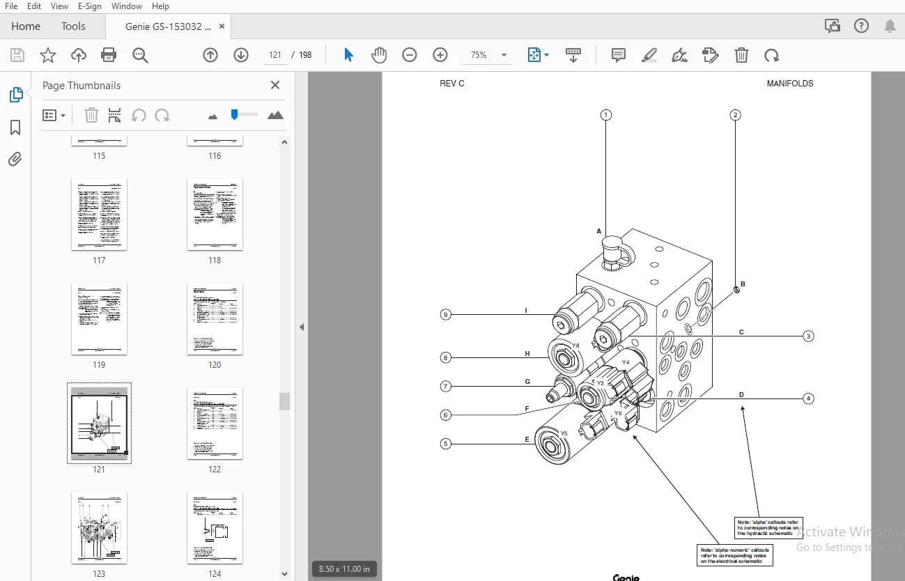
Important Information...........................................................................................................  2
Table of Contents...............................................................................................................  7
Section 1 • Safety Rules........................................................................................................  5
Section 2 • Specifications - Rev E.............................................................................................. 13
	Machine Specifications ..................................................................................................... 13
	Performance Specifications.................................................................................................. 14
	Hydraulic Specifications.................................................................................................... 15
	Manifold Component Specifications........................................................................................... 16
	Hydraulic Hose and Fitting Torque Specifications............................................................................ 17
	SAE and Metric Fasteners Torque Chart....................................................................................... 19
Section 3 • Scheduled Maintenance Procedures.................................................................................... 21
	Introduction................................................................................................................ 21
	Pre-delivery Preparation Report............................................................................................. 23
	Maintenance Inspection Report............................................................................................... 25
	Checklist A Procedures - Rev C.............................................................................................. 26
		A-1 Inspect the Manuals and Decals...................................................................................... 26
		A-2  Perform Pre-operation Inspection................................................................................... 27
		A-3  Perform Function Tests............................................................................................. 27
		A-4  Perform 30 Day Service............................................................................................. 28
		A-5  Grease the Steer Yokes............................................................................................. 28
	Checklist B Procedures - Rev F.............................................................................................. 29
		B-1 Inspect the Batteries............................................................................................... 29
		B-2 Inspect the Electrical Wiring....................................................................................... 31
		B-3 Inspect the Tires and Wheels (including castle nut torque).......................................................... 32
		B-4 Test the Emergency Stop............................................................................................. 32
		B-5 Test the Key Switch................................................................................................. 33
		B-6 Test the Automotive-style Horn (if equipped)........................................................................ 33
		B-7 Test the Drive Brakes............................................................................................... 34
		B-8 Test the Drive Speed - Stowed Position.............................................................................. 37
		B-9 Test the Drive Speed - Raised Position.............................................................................. 38
		B-10 Perform Hydraulic Oil Analysis..................................................................................... 39
		B-11 Inspect the Hydraulic Tank Cap Venting System...................................................................... 39
		B-12 Check the Module Tray Latch Components............................................................................. 40
		B-13 Inspect the Voltage Inverter (if equipped)......................................................................... 41
		B-14 Test the Down Limit Switch and the Pothole Limit Switches.......................................................... 42
		B-15 Test the Up Limit Switch (if equipped)............................................................................. 45
	Checklist C Procedure - Rev C............................................................................................... 46
		C-1 Test the Platform Overload System (if equipped)..................................................................... 46
		C-2 Replace the Hydraulic Tank Breather Cap - Models with Optional Hydraulic Oil........................................ 48
	Checklist D Procedures - Rev C.............................................................................................. 49
		D-1 Check the Scissor Arm Wear Pads..................................................................................... 49
		D-2 Replace the Hydraulic Tank Return Filter............................................................................ 51
	Checklist E Procedure - Rev B............................................................................................... 52
		E-1 Test or Replace the Hydraulic Oil................................................................................... 52
Section 4 • Repair Procedures................................................................................................... 55
	Introduction................................................................................................................ 55
	Platform Controls - Rev D................................................................................................... 56
		1-1 Circuit Boards...................................................................................................... 57
		1-2 Controller Adjustments.............................................................................................. 58
		1-3 Software Configuration (before serial numbers GS3005-75000, GS3205-75000 and GS4605-75000).......................... 63
		1-4 Software Configuration (after serial numbers GS3005-74999, GS3205-74999 and GS4605-74999)........................... 66
	Platform Components - Rev A................................................................................................. 70
		2-1 Platform............................................................................................................ 70
		2-2 Platform Extension.................................................................................................. 71
	Scissor Components - Rev C.................................................................................................. 72
		3-1 Scissor Assembly, GS-1530 and GS-1532............................................................................... 72
		3-2 Scissor Assembly, GS-1930 and GS-1932............................................................................... 79
		3-3 Scissor Assembly, GS-2032 and GS-2046............................................................................... 86
		3-4 Scissor Assembly, GS-2632 and GS-2646............................................................................... 92
		3-5 Scissor Assembly, GS-3246...........................................................................................100
		3-6 Lift Cylinder.......................................................................................................108
	Ground Controls - Rev B.....................................................................................................113
		4-1 Manual Platform Lowering Cable......................................................................................113
		4-2 Control Relays......................................................................................................114
		4-3 Level Sensor........................................................................................................115
	Hydraulic Pump - Rev A......................................................................................................118
		5-1 Function Pump.......................................................................................................118
	Manifolds - Rev C...........................................................................................................120
		6-1 Function Manifold Components - GS-1530, GS-1532, GS-1930 and GS-1932................................................120
		6-2 Function Manifold Components - GS-2032, GS-2632, GS-2046, GS-2646 and GS-3246.......................................122
		6-3 Check Valve Manifold Components - GS-1530, GS-1532, GS-1930 and GS-1932 (after serial number GS3004-66986)..........124
		6-4 Valve Adjustments - Function Manifold...............................................................................125
		6-5 Valve Coils.........................................................................................................129
	Hydraulic Tank - Rev B......................................................................................................131
		7-1 Hydraulic Tank......................................................................................................131
	Steer Axle Components - Rev B...............................................................................................132
		8-1 Yoke and Drive Motor................................................................................................132
		8-2 Steer Cylinder......................................................................................................133
		8-3 Steer Bellcrank.....................................................................................................134
	Non-steer Axle Components - Rev A...........................................................................................135
		9-1 Drive Brake.........................................................................................................135
	Brake Release Hand Pump Components - Rev A..................................................................................136
		10-1 Brake Release Hand Pump Components.................................................................................136
	Platform Overlaod System - Rev B............................................................................................137
		11-1 Platform Overload System...........................................................................................137
Section 5 • Fault Codes.........................................................................................................141
	Introduction................................................................................................................141
	Fault Code Chart - Rev A....................................................................................................143
Section 6 • Schematics..........................................................................................................145
	Introduction................................................................................................................145
	Electrical Component and Wire Color Legends - Rev A.........................................................................146
	ECM Pin-out Legend - Rev C..................................................................................................147
	Wiring Diagram - Ground Controls and Level Sensor Harness - Rev B...........................................................148
	Wiring Diagram - Platform Control Box - Rev B...............................................................................149
	Limit Switch Legend - Rev B.................................................................................................150
	Electrical Symbols Legend - Rev A...........................................................................................151
	Electrical Schematics - ANSI, CSA and Australia Models......................................................................152
		Electrical Schematic - GS-1530/1532/1930/1932 ANSI (from serial number GS3003-60000 to GS3005-74999) - Rev C............152
		Electrical Schematic - GS-1530/1532/1930/1932 ANSI (from serial number GS3005-75000 to 75999) - Rev B...................156
		Electrical Schematic - GS-2032/2632 ANSI (from serial number GS3204-60000 to GS3205-74999) - Rev D......................160
		Electrical Schematic - GS-2032/2632 ANSI (from serial number GS3205-75000 to 75406) - Rev B.............................164
		Electrical Schematic - GS-2046/2646/3246 ANSI (from serial number GS4604-60000 to GS4605-74999) - Rev D.................160
		Electrical Schematic - GS-2046/2646/3246 ANSI (from serial number GS4605-75000 to 75437) - Rev B........................164
	Electrical Schematics - CE Models...........................................................................................168
		Electrical Schematic - GS-1532/1932 CE (from serial number GS3003-60000 to GS3005-74999) - Rev C........................168
		Electrical Schematic - GS-1532/1932 CE (from serial number GS3005-75000 to 75999) - Rev B...............................172
		Electrical Schematic - GS-2032/2632 CE (from serial number GS3204-60000 to GS3205-74999) - Rev D........................176
		Electrical Schematic - GS-2032/2632 CE (from serial number GS3205-75000 to 75406) - Rev B...............................180
		Electrical Schematic - GS-2046/2646/3246 CE (from serial number GS4604-60000 to GS4605-74999) - Rev D...................176
		Electrical Schematic - GS-2046/2646/3246 CE (from serial number GS4605-75000 to 75437) - Rev B..........................180
	Hydraulic Schematics........................................................................................................183
		Component Reference and Hydraulic Symbols Legend - Rev A................................................................183
		Hydraulic Schematic, GS-1530, GS-1532, GS-1930 and GS-1932 (from serial number GS3003-60000 to GS3004-65104) - Rev A....184
		Hydraulic Schematic, GS-1530, GS-1532, GS-1930 and GS-1932 (from serial number GS3004-65105 to 66986) - Rev B...........186
		Hydraulic Schematic, GS-1530, GS-1532, GS-1930 and GS-1932 (from serial number GS3004-66987 to GS3005-75999) - Rev A....188
		Hydraulic Schematic, GS-2032 and GS-2632 (from serial number GS3204-60000 to GS3205-75406) - Rev A......................190
		Hydraulic Schematic - GS-2046, GS-2646 and GS-3246 (from serial number GS4604-60000 to GS4604-60878) - Rev B............192
		Hydraulic Schematic - GS-2046, GS-2646 and GS-3246 (from serial number GS4604-60879 to GS4605-75437) - Rev A............194
S.S 04/24