Trusted Business
Verified & Licensed
Virus Free Files
100% Safe Downloads
Secure Payment
SSL Protected
Instant Delivery
Available Immediately
Genie GS-2032 GS-2632 Service Manual 72963 – PDF DOWNLOAD
$26.95
Genie GS-2032 GS-2632 Service Manual 72963 – PDF DOWNLOAD
Instant PDF Download
Available immediately
Save to Your Device
Download & keep forever
Antivirus Scanned
100% virus-free
Trusted Worldwide
175,000+ customers
Description
Genie GS-2032 GS-2632 Service Manual 72963 – PDF DOWNLOAD
Language : English
Pages : 196
Downloadable : Yes
File Type : PDF
Table of Contents:
Genie GS-2032 GS-2632 Service Manual 72963 – PDF DOWNLOAD
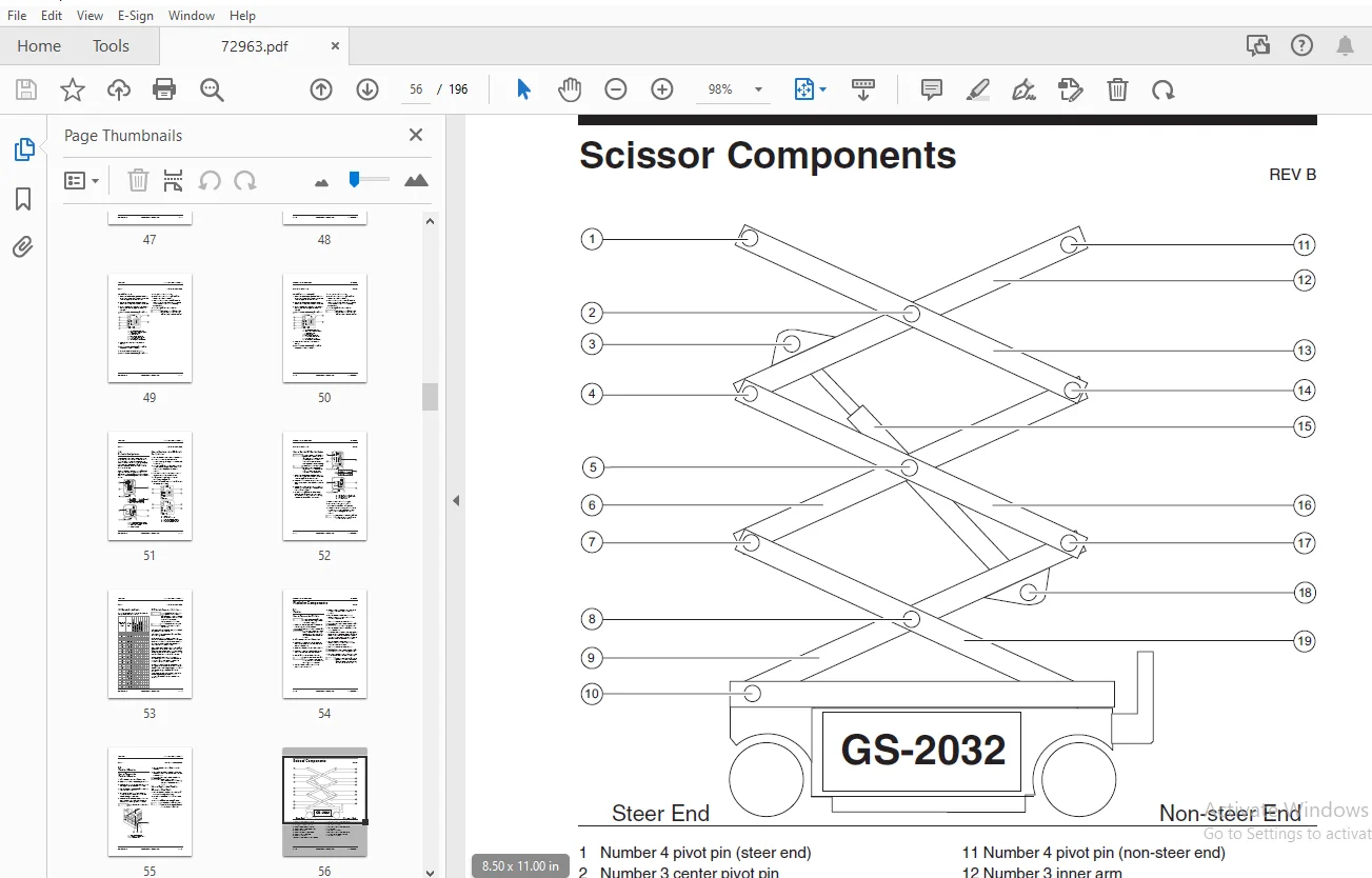
Important Information.........................................................................  2
Safety Rules..................................................................................  3
Table of Contents.............................................................................  5
Section 2 • Specifications.................................................................... 11
	Machine Specifications.................................................................... 11
	Performance Specifications................................................................ 11
	Hydraulic Specifications.................................................................. 12
	Manifold Component Specifications......................................................... 13
	Hydraulic Hose and Fitting Torque Specifications.......................................... 14
Section 3 • Scheduled Maintenance Procedures.................................................. 17
	Introduction.............................................................................. 17
	Pre-delivery Preparation Report........................................................... 19
	Maintenance Inspection Report............................................................. 21
	Checklist A Procedures - Rev B............................................................ 22
		A-1  Perform Pre-operation Inspection................................................. 22
		A-2  Perform Function Tests........................................................... 22
		A-3  Perform 30 Day Service........................................................... 23
		A-4  Grease the Steer Yokes........................................................... 23
	Checklist B Procedures - Rev D............................................................ 24
		B-1 Inspect the Batteries............................................................. 24
		B-2 Inspect the Electrical Wiring..................................................... 25
		B-3 Inspect the Tires and Wheels (including castle nut torque)........................ 26
		B-4 Test the Emergency Stop........................................................... 26
		B-5 Test the Key Switch............................................................... 27
		B-6 Test the Automotive-style Horn (if equipped)...................................... 27
		B-7 Test the Drive Brakes............................................................. 28
		B-8 Test the Drive Speed - Stowed Position............................................ 31
		B-9 Test the Drive Speed - Raised Position............................................ 32
		B-10 Perform Hydraulic Oil Analysis................................................... 33
		B-11 Replace the Hydraulic Tank Return Filter......................................... 33
		B-12 Check the Module Tray Latch Components........................................... 34
	Checklist C Procedure - Rev C............................................................. 35
		C-1 Test the Platform Overload System (if equipped)................................... 35
	Checklist D Procedures - Rev D............................................................ 37
		D-1 Check the Scissor Arm Wear Pads................................................... 37
	Checklist E Procedure - Rev A............................................................. 38
		E-1 Test or Replace the Hydraulic Oil................................................. 38
Section 4 • Repair Procedures................................................................. 39
	Introduction.............................................................................. 39
	Platform Controls - Rev B................................................................. 40
		1-1 Circuit Boards.................................................................... 41
		1-2 Joystick Controller............................................................... 41
		1-3 Controller Adjustments............................................................ 43
		1-4 Software Configuration............................................................ 51
	Platform Components - Rev B............................................................... 54
		2-1 Platform.......................................................................... 54
		2-2 Platform Extension................................................................ 55
	Scissor Components - Rev D................................................................ 56
		3-1 Scissor Assembly, GS-2032......................................................... 56
		3-2 Scissor Assembly, GS-2632......................................................... 62
		3-3 Lift Cylinder..................................................................... 70
		3-4 Platform Overload System.......................................................... 72
	Ground Controls - Rev C................................................................... 74
		4-1 Manual Platform Lowering Cable.................................................... 74
		4-2 Control Relays.................................................................... 75
		4-3 Level Sensor (before serial number 47665)......................................... 76
		4-4 Level Sensor (after serial number 47664).......................................... 82
	Hydraulic Pump - Rev A.................................................................... 88
		5-1 Function Pump..................................................................... 88
	Manifolds - Rev C......................................................................... 90
		6-1 Function Manifold Components (from serial number 17408 to 17481).................. 90
		6-2 Function Manifold Components (from serial number 17482 to 36100).................. 92
		6-3 Function Manifold Components (from serial number 36101 to 49245).................. 94
		6-4 Function Manifold Components (from serial number 49246 to 59999).................. 96
		6-5 Function Manifold Components - Models with Traction Control....................... 98
		6-6 Valve Adjustments - Function Manifold.............................................100
		6-7 Valve Coils.......................................................................108
	Hydraulic Tank - Rev A....................................................................110
		7-1 Hydraulic Tank....................................................................110
	Steer Axle Components - Rev A.............................................................111
		8-1 Yoke and Drive Motor..............................................................111
		8-2 Steer Cylinder....................................................................113
		8-3 Steer Bellcrank...................................................................114
	Non-steer Axle Components - Rev A.........................................................115
		9-1 Drive Brake.......................................................................115
	Brake Release Hand Pump Components - Rev B................................................116
		10-1 Brake Release Hand Pump Components...............................................116
Section 5 • Troubleshooting Flow Charts.......................................................117
	Introduction..............................................................................117
	Fault Code Chart (after serial number 17407) - Rev A......................................119
	Chart 1 All Functions Will Not Operate - Rev A............................................120
	Chart 2 Pump Motor Will Not Operate - Rev A...............................................122
	Chart 3 All Functions Inoperative, Power Unit Starts and Runs - Rev A.....................124
	Chart 4 Ground Controls Inoperative, Platform Controls Operate Normally - Rev A...........125
	Chart 5 Platform Controls Inoperative, Ground Controls Operate Normally - Rev A...........126
	Chart 6 Platform Up Function Inoperative - Rev A..........................................127
	Chart 7 Platform Down Function Inoperative - Rev A........................................128
	Chart 8 Steer Left Function Inoperative - Rev A...........................................130
	Chart 9 Steer Right Function Inoperative - Rev A..........................................132
	Chart 10 All Drive Functions Inoperative, All Other Functions Operate Normally - Rev A....134
	Chart 10A Brake Release Function Inoperative - Rev A......................................135
	Chart 11 Drive Forward Function Inoperative - Rev A.......................................136
	Chart 12 Drive Reverse Function Inoperative - Rev A.......................................137
	Chart 13 Machine Will Not Drive At Full Speed - Rev A.....................................138
	Chart 14 Machine Drives At Full Speed With Platform Raised - Rev A........................139
	Chart 15 Limit Switch Function Inoperative - Rev A........................................140
	Chart 16 Fault Code 02 - ECM / Platform Communication Error - Rev A.......................142
	Chart 17 Fault Code 59 - Parallel/Series Coil Fault - Rev B...............................145
Section 6 • Schematics........................................................................147
	Introduction..............................................................................147
	Control Relay Layout - GS-2032 (ANSI, CSA and Australia models) - Rev B...................148
	Control Relay Layout - GS-2032 (CE models) and GS-2632 (all models) - Rev B...............149
	ECM Pin-out Legend - Rev B................................................................150
	Platform Controls Wiring Diagram (models with potentiometer-equipped joystick) - Rev B....152
	Platform Controls Wiring Diagram (models with hall-effect joystick) - Rev A...............153
	Ground Controls Wiring Diagram - Rev B....................................................154
	Level Sensor Box Wiring Diagram - Rev B...................................................155
	Electrical Symbols Legend - Rev B.........................................................156
	Electrical Schematic (from serial number 17408 to 21064) - Rev B..........................158
	Electrical Schematic (from serial number 21065 to 25141) - Rev B..........................162
	Electrical Schematic (from serial number 25142 to 28936) - Rev B..........................166
	Electrical Schematic (from serial number 28937 to 40925) - Rev B..........................170
	Electrical Schematic (from serial number 40926 to 48103) - Rev B..........................174
	Electrical Schematic (from serial number 48104 to 49299) - Rev A..........................178
	Electrical Schematic (from serial number 49300 to 59999) - Rev A..........................182
	Hydraulic Symbols Legend and Component Reference - Rev B..................................186
	Hydraulic Schematic (from serial number 17408 to 36100) - Rev B...........................187
	Hydraulic Schematic (from serial number 36101 to 52788) - Rev B...........................189
	Hydraulic Schematic (from serial number 52789 to 59999) - Rev A...........................191
	Hydraulic Schematic - Models with Traction Control  - Rev B...............................193
S.S 04/24