Trusted Business
Verified & Licensed
Virus Free Files
100% Safe Downloads
Secure Payment
SSL Protected
Instant Delivery
Available Immediately
Genie GS-2046 GS-2646 GS-3246 Service Manual 48339 – PDF DOWNLOAD
$26.95
Genie GS-2046 GS-2646 GS-3246 Service Manual 48339 – PDF DOWNLOAD
Instant PDF Download
Available immediately
Save to Your Device
Download & keep forever
Antivirus Scanned
100% virus-free
Trusted Worldwide
175,000+ customers
Description
Genie GS-2046 GS-2646 GS-3246 Service Manual 48339 – PDF DOWNLOAD
Language : English
Pages : 163
Downloadable : Yes
File Type : PDF
Table of Contents:
Genie GS-2046 GS-2646 GS-3246 Service Manual 48339 – PDF DOWNLOAD
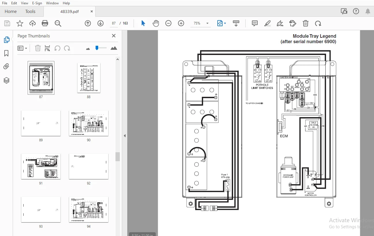
Front Cover
............................................................................  1
Introduction............................................................................  2
Important Information...................................................................  2
Section One Safety Rules................................................................  3
	General Safety Rules................................................................  3
	Theory of Operation.................................................................  5
Section Two Specifications.............................................................. 13
	Machine Specifications, GS-2046..................................................... 13
	Machine Specifications, GS-2646..................................................... 14
	Machine Specifications, GS-3246..................................................... 15
	Performance Specifications, All Models.............................................. 16
	Hydraulic Specifications, All Models................................................ 16
	Hydraulic Hose and Fitting Torque Specifications.................................... 17
Section Three Scheduled Maintenance Inspections......................................... 19
	Introduction........................................................................ 19
	Maintenance Tables.................................................................. 20
		Table A......................................................................... 20
		Table B......................................................................... 20
		Table C......................................................................... 21
		Table D......................................................................... 21
	Maintenance Inspection Report....................................................... 22
Section Four Scheduled Maintenance Procedures........................................... 23
	Introduction........................................................................ 23
	Table A Procedures.................................................................. 24
		A-1  Inspect the Operator’s and Safety Manuals.................................. 24
		A-2  Inspect the Decals and Placards............................................ 24
		A-3  Inspect for Damage and Loose or Missing Parts.............................. 25
		A-4 Check the Hydraulic Oil Level............................................... 26
		 A-5 Check for Hydraulic Leaks.................................................. 26
		A-6 Test the Platform and Ground Controls....................................... 27
		A-7 Test the Manual Platform Lowering Operation................................. 28
		A-8 Test the Tilt Sensor........................................................ 28
		A-9 Test the Pothole Guards..................................................... 29
		A-10 Test the Lift/Drive Select Switch (before serial number 17408)............. 29
		A-11 Perform 30 Day Service..................................................... 30
	Table B Procedures.................................................................. 31
		B-1 Check the Batteries......................................................... 31
		B-2 Inspect the Electrical Wiring............................................... 32
		B-3 Inspect the Tires and Wheels (including castle nut torque).................. 33
		B-4 Test the Key Switch......................................................... 33
		B-5 Test the Emergency Stop Buttons............................................. 34
		B-6 Test the Service Horn....................................................... 34
		B-7 Test the Drive Brakes....................................................... 35
		B-8 Test the Drive Speed - Stowed Position...................................... 37
		B-9 Test the Drive Speed - Raised Position...................................... 37
		B-10 Perform Hydraulic Oil Analysis............................................. 38
		B-11 Check the Electrical Contactor (before serial number 6901)................. 38
		B-12 Replace the Hydraulic Return Filter........................................ 39
	Table C Procedure................................................................... 40
		C-1 Check the Module Tray Latch Components...................................... 40
	Table D Procedure................................................................... 41
		D-1 Test or Replace the Hydraulic Oil........................................... 41
Section Five Troubleshooting Flow Charts and Fault Codes................................ 43
	Introduction........................................................................ 43
	Fault Code Chart (Before Serial Number 17408)....................................... 45
	Normal Operation Code Chart (Before Serial Number 17408)............................ 48
	Fault Code Chart (After Serial Number 17407)........................................ 50
	Chart 1 All Functions Will Not Operate.............................................. 51
	Chart 2 Pump Motor Will Not Operate - before serial number 6901..................... 54
	Chart 3 Pump Motor Will Not Operate - after serial number 6900...................... 56
	Chart 4 All Functions Inoperative, Power Unit Starts and Runs....................... 58
	Chart 5 Ground Controls Inoperative, Platform Controls Operate Normally............. 59
	Chart 6 Platform Controls Inoperative, Ground Controls Operate Normally............. 60
	Chart 7 Platform Up Function Inoperative............................................ 62
	Chart 8 Platform Down Function Inoperative, GS-2046 & GS-2646 Models................ 63
	Chart 9 Platform Down Function Inoperative, GS-3246 Models.......................... 65
	Chart 10 Steer Left Function Inoperative............................................ 67
	Chart 11 Steer Right Function Inoperative........................................... 69
	Chart 12 All Drive Functions Inoperative, All Other Functions Operate Normally...... 71
	Chart 13 Brake Release Function Inoperative......................................... 73
	Chart 14 Drive Forward Function Inoperative......................................... 74
	Chart 15 Drive Reverse Function Inoperative......................................... 75
	Chart 16 Machine Will Not Drive At Full Speed....................................... 76
	Chart 17 Machine Drives At Full Speed With Platform Raised.......................... 78
	Chart 18 Manual Platform Lowering Function Inoperative, GS-2046 & GS-2646........... 79
	Chart 19 Manual Platform Lowering Function Inoperative, GS-3246..................... 80
	Chart 20 Drive Function Overspeeds While Driving Down an Incline, GS-3246 Models.... 81
	Chart 21 Drive Function Hesitates While Steering, GS-3246 Models.................... 82
Section Six Schematics.................................................................. 83
	Introduction........................................................................ 83
	Electrical Components............................................................... 84
	Module Tray Legend (before serial number 6901)...................................... 86
	Module Tray Legend (after serial number 6900)....................................... 87
	Electrical Symbols Legend........................................................... 88
	Electrical Schematic (before serial number 6901).................................... 90
	Electrical Schematic (from serial number 6901 to 8931).............................. 94
	Electrical Schematic (from serial number 8932 to 17407)............................. 98
	Electrical Schematic (after serial number 17407)....................................102
	Ground Controls and Level Sensor Box Legend.........................................105
	Platform Controls Legend (before serial number 17408)...............................106
	Platform Controls Legend (after serial number 17407)................................107
	Hydraulic Symbols Legend............................................................108
	Hydraulic Schematic (before serial number 17482)....................................109
	Hydraulic Schematic (after serial number 17481).....................................111
Section Seven Repair Procedures.........................................................113
	Introduction........................................................................113
	Platform Controls...................................................................114
		1-1 Joystick Controller.........................................................114
		1-2 Software Configuration......................................................115
		1-3 How to Set the DIP Switch Codes.............................................116
		1-4 Toggle Switches.............................................................118
	Platform Components.................................................................119
		2-1 Platform....................................................................119
		2-2 Platform Extension..........................................................120
	Scissor Components..................................................................122
		3-1 Scissor Assembly, GS-2046...................................................122
		3-2 Scissor Assembly, GS-2646...................................................128
		3-3 Scissor Assembly, GS-3246...................................................136
		3-4 Lift Cylinder...............................................................144
	Ground Controls.....................................................................147
		4-1 Manual Platform Lowering Cable, GS-2046 & GS-2646 ..........................147
		4-2 Manual Platfrom Lowering, GS-3246...........................................148
		4-3 Toggle Switches, See 1-4, Toggle Switches...................................118
	Hydraulic Pump......................................................................149
		5-1 Hydraulic Pump..............................................................149
	Manifolds...........................................................................150
		6-1 Function Manifold Components (before serial number 17482)...................150
		6-2 Function Manifold Components (after serial number 17481)....................152
		6-3 Valve Adjustments - Function Manifold.......................................154
		6-4 Valve Adjustments - Lift Relief Valve, GS-3246..............................156
		6-5 Valve Adjustments - Back Pressure Relief Valve..............................157
	Steering Axle Components............................................................158
		7-1 Yoke and Drive Motor........................................................158
		7-2 Steering Cylinder...........................................................160
		7-3 Steering Bellcrank..........................................................160
	Non-steering Axle Components........................................................161
		8-1 Drive Brake.................................................................161
	Brake Release Hand Pump Components..................................................162
		9-1 Brake Release Hand Pump.....................................................162
Back Cover
.............................................................................163
S.S 04/24