Trusted Business
Verified & Licensed
Virus Free Files
100% Safe Downloads
Secure Payment
SSL Protected
Instant Delivery
Available Immediately
Genie GS-2668 RT GS-3268 RT Service Manual 112657 – PDF DOWNLOAD
$26.95
Genie GS-2668 RT GS-3268 RT Service Manual 112657 – PDF DOWNLOAD
Instant PDF Download
Available immediately
Save to Your Device
Download & keep forever
Antivirus Scanned
100% virus-free
Trusted Worldwide
175,000+ customers
Description
Genie GS-2668 RT GS-3268 RT Service Manual 112657 – PDF DOWNLOAD
Language : English
Pages : 183
Downloadable : Yes
File Type : PDF
Table of Contents:
Genie GS-2668 RT GS-3268 RT Service Manual 112657 – PDF DOWNLOAD
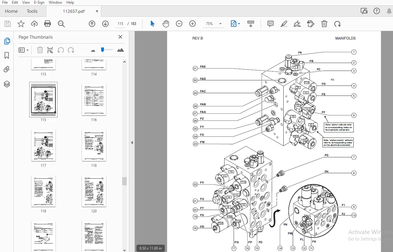
Front Cover...............................................................................................................  1
Introduction..............................................................................................................  2
Table of Contents.........................................................................................................  7
Section 1 •  Safety Rules.................................................................................................  5
	General Safety Rules..................................................................................................  5
Section 2 • Specifications - Rev D........................................................................................ 15
	Machine Specifications................................................................................................ 15
	Performance Specifications............................................................................................ 16
	Hydraulic Specifications.............................................................................................. 16
	Hydraulic Component Specifications.................................................................................... 17
	Manifold Component Specifications..................................................................................... 18
	Valve Coil Resistance Specifications.................................................................................. 18
	Kubota 1105 Engine Tier 4............................................................................................. 19
	Kubota D905 Engine Tier 2............................................................................................. 20
	Kubota DF752 Engine................................................................................................... 21
	Perkins 403D-11 Engine................................................................................................ 22
	Perkins 403C-11 Engine................................................................................................ 23
	Hydraulic Hose and Fitting Torque Specifications...................................................................... 24
	SAE and Metric Fasteners Torque Charts................................................................................ 25
Section 3 • Scheduled Maintenance Procedures.............................................................................. 27
	Introduction.......................................................................................................... 27
	Pre-delivery Preparation.............................................................................................. 29
	Maintenance Inspection Report......................................................................................... 31
	Checklist A Prodcedures - Rev B....................................................................................... 33
		A-1 Inspect the Manuals and Decals................................................................................ 33
		A-2 Perform Pre-operation Inspection.............................................................................. 34
		A-3 Perform Function Tests........................................................................................ 34
		A-4 Perform Engine Maintenance.................................................................................... 35
		A-5 Inspect the Engine Air Filter................................................................................. 35
		A-6 Perform 30 Day Service........................................................................................ 36
		A-7 Perform Engine Maintenance - Kubota Models.................................................................... 37
		A-8 Perform Engine Maintenance - Kubota Models.................................................................... 37
		A-9 Perform Engine Maintenance - Kubota Models.................................................................... 38
		A-10 Perform Engine Maintenance - Kubota Models................................................................... 38
		A-11 Drain the Fuel Filter/Water Separator - Diesel Models........................................................ 39
		A-12 Perform Engine Maintenance - Kubota Models................................................................... 40
	Checklist B Prodcedures - Rev B....................................................................................... 41
		B-1 Inspect the Battery........................................................................................... 41
		B-2 Inspect the Electrical Wiring................................................................................. 42
		B-3 Inspect the Tires, Wheels and Lug Bolt Torque................................................................. 43
		B-4 Perform Engine Maintenance - Perkins Models................................................................... 43
		B-5 Test the Key Switch........................................................................................... 44
		B-6 Test the Emergency Stop....................................................................................... 44
		B-7 Test the Automotive-style Horn................................................................................ 45
		B-8 Test the Fuel Select Operation - Gasoline/LPG Models.......................................................... 45
		B-9 Test the Drive Brakes......................................................................................... 46
		B-10 Test the Drive Speed - Stowed Position....................................................................... 47
		B-11 Test the Drive Speed - Raised Position....................................................................... 48
		B-12 Inspect the Fuel and Hydraulic Tank Cap Venting Systems...................................................... 48
		B-13 Perform Hydraulic Oil Analysis............................................................................... 49
		B-14 Test the Flashing Beacons (if equipped)...................................................................... 50
		B-15  Perform Engine Maintenance - Kubota Models.................................................................. 50
	Checklist C Prodcedures - Rev B....................................................................................... 51
		C-1 Test the Platform Overload System (if equipped)............................................................... 51
		C-2 Clean the Fuel Tank - Diesel Models........................................................................... 52
		C-3 Replace the Hydraulic Tank Breather Cap - Models with Optional Hydraulic Oil.................................. 53
		C-4 Perform Engine Maintenance - Diesel Models.................................................................... 53
		C-5 Perform Engine Maintenance - Kubota Models.................................................................... 54
	Checklist D Prodcedures - Rev B....................................................................................... 55
		D-1 Check the Scissor Arm Wear Pads............................................................................... 55
		D-2 Replace the Hydraulic Tank Return Filter...................................................................... 56
		D-3 Perform Engine Maintenance - Perkins Models................................................................... 57
		D-4 Perform Engine Maintenance - Kubota Models.................................................................... 57
		D-5 Perform Engine Maintenance - Kubota Models.................................................................... 58
	Checklist E Procedures - Rev B........................................................................................ 59
		E-1 Test or Replace the Hydraulic Oil............................................................................. 59
		E-2  Perform Engine Maintenance - Perkins Models.................................................................. 60
		E-3 Perform Engine Maintenance - Gasoline/LPG Models.............................................................. 61
		E-4 Perform Engine Maintenance - Kubota D1105 Models.............................................................. 61
		E-5 Perform Engine Maintenance - Perkins Models................................................................... 62
		E-6 Perform Engine Maintenance - Kubota D1105 Models.............................................................. 62
Section 4 • Repair Procedures............................................................................................. 63
	Introduction.......................................................................................................... 63
	Platform Controls - Rev A............................................................................................. 64
		1-1  Circuit Boards............................................................................................... 64
	Platform Components - Rev A........................................................................................... 65
		2-1  Platform..................................................................................................... 65
		2-2  Platform Extension Deck...................................................................................... 66
	Scissor Components - Rev B............................................................................................ 68
		3-1  Scissor Assembly, GS-2668 RT................................................................................. 69
		3-2  Scissor Assembly, GS-3268 RT................................................................................. 75
		3-3  Wear Pads.................................................................................................... 81
		3-4  Lift Cylinder(s)............................................................................................. 82
	Kubota D1105 and D905 Engines - Rev C................................................................................. 85
		4-1  Timing Adjustment............................................................................................ 85
		4-2  Glow Plugs................................................................................................... 85
		4-3  Engine RPM................................................................................................... 86
		4-4  Flex Plate................................................................................................... 86
		4-5  Coolant Temperature and Oil Pressure Switches................................................................ 87
	Kubota DF752 Engine - Rev A........................................................................................... 89
		5-1  Timing Adjustment............................................................................................ 89
		5-2  Carburetor Adjustment........................................................................................ 89
		5-3  Choke Adjustment - Gasoline/LPG Models....................................................................... 89
		5-4  Flex Plate................................................................................................... 89
		5-5  Coolant Temperature and Oil Pressure Switches................................................................ 89
		5-6  Engine RPM................................................................................................... 90
	Perkins 403D-11 and 403C-11 Engines - Rev B........................................................................... 91
		6-1  Engine RPM................................................................................................... 91
		6-2  Timing Adjustment............................................................................................ 91
		6-3  Flex Plate................................................................................................... 92
		6-4  Coolant Temperature and Oil Pressure Switches................................................................ 92
	Ground Controls - Rev B............................................................................................... 94
		7-1  Auxiliary Platform Lowering.................................................................................. 94
		7-2  Function Speed Tuning........................................................................................ 94
		7-3  Software Configuration....................................................................................... 99
		7-4  Level Sensor - Models without Outriggers.....................................................................105
		7-5  Level Sensor - Models with Outriggers........................................................................108
	Hydraulic Pump - Rev A................................................................................................112
		8-1  Hydraulic Pump...............................................................................................112
	Manifolds - Rev B.....................................................................................................114
		9-1  Function Manifold Components.................................................................................114
		9-2  Valve Adjustments - Function Manifold........................................................................118
		9-3  Outrigger Manifold Components................................................................................121
		9-4  Valve Adjustments - Outrigger Manifold.......................................................................122
		9-5  Generator Manifold Components................................................................................124
		9-6  Valve Adjustments - Generator Manifold.......................................................................125
		9-7  Valve Coils..................................................................................................126
	Fuel and Hydraulic Tanks - Rev A......................................................................................128
		10-1  Fuel Tank...................................................................................................128
		10-2  Hydraulic Tank..............................................................................................129
	Steer Axle Components - Rev A.........................................................................................130
		11-1  Yoke and Drive Motor........................................................................................130
		11-2  Steer Cylinder..............................................................................................132
		11-3  Tie Rod.....................................................................................................132
	Non-steer Axle Components - Rev A.....................................................................................133
		12-1  Drive Motor and Brake.......................................................................................133
	Outrigger Components - Rev A..........................................................................................134
		13-1  Outrigger Cylinder..........................................................................................134
	Brake Release Hand Pump Components - Rev A............................................................................135
		14-1  Brake Release Hand Pump Components..........................................................................135
	Platform Overload Components - Rev A..................................................................................136
		15-1 Platform Overload System.....................................................................................136
Section 5 • Fault Codes...................................................................................................143
	Introduction..........................................................................................................143
	Fault Code Chart (from serial number GS6805-44771) - Rev B............................................................145
Section 6 • Schematics....................................................................................................149
	Introduction..........................................................................................................149
	Electrical............................................................................................................150
		Electronic Control Module Layout (from serial number GS6805-44771) - Rev A........................................150
		Electronic Control Module Pin-Out Legend (from serial number GS6805-44771) - Rev A................................151
		Wiring Diagram - Platform Control Box (from serial number GS6805-44771) - Rev A...................................152
		Electrical Schematics Abbreviations and Wire Color Legends - Rev B................................................154
		Electrical Symbols Legend - Rev A.................................................................................155
		Electrical Schematic - ANSI Models with Gasoline/LPG Power (from serial number GS6805-44771) - Rev C..............156
		Electrical Schematic - CE Models with Gasoline/LPG Power (from serial number GS6805-44771) - Rev C................160
		Electrical Schematic - ANSI Models with Diesel Power (from serial number GS6805-44771 to GS6806-45204) - Rev C....164
		Electrical Schematic - ANSI Models with Diesel Power (from serial number GS6806-45205) - Rev C....................168
		Electrical Schematic - CE Models with Diesel Power (from serial number GS6805-44771 to GS6806-45204) - Rev C......172
		Electrical Schematic - CE Models with Diesel Power (from serial number GS6806-45205) - Rev C......................176
	Hydraulic.............................................................................................................179
		Hydraulic Symbols Legend - Rev A..................................................................................179
		Hydraulic Schematic (from serial number GS6805-44771) - Rev C.....................................................180
S.S 04/24