Trusted Business
Verified & Licensed
Virus Free Files
100% Safe Downloads
Secure Payment
SSL Protected
Instant Delivery
Available Immediately
Genie GS-2668 RT GS-3268 RT Service Manual 52302 – PDF DOWNLOAD
$28.95
Genie GS-2668 RT GS-3268 RT Service Manual 52302 – PDF DOWNLOAD
Instant PDF Download
Available immediately
Save to Your Device
Download & keep forever
Antivirus Scanned
100% virus-free
Trusted Worldwide
175,000+ customers
Description
Genie GS-2668 RT GS-3268 RT Service Manual 52302 – PDF DOWNLOAD
Language : English
Pages : 286
Downloadable : Yes
File Type : PDF
Table of Contents:
Genie GS-2668 RT GS-3268 RT Service Manual 52302 – PDF DOWNLOAD
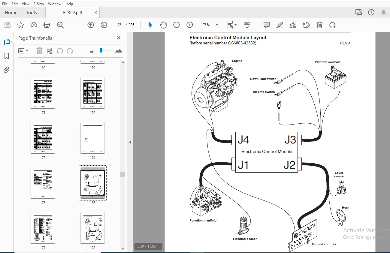
Table of Contents...............................................................................................................  7
Section 1 • Safety Rules........................................................................................................  5
	General Safety Rules........................................................................................................  5
Section 2 • Specifications - Rev D.............................................................................................. 17
	Machine Specifications...................................................................................................... 17
	Performance Specifications.................................................................................................. 18
	Hydraulic Specifications.................................................................................................... 18
	Manifold Component Specifications........................................................................................... 19
	Kubota D905 Engine (before serial number GS6805-43886)...................................................................... 20
	Kubota D905 Engine Tier 2 (after serial number GS6805-43885)................................................................ 21
	Perkins 403C-11 Engine...................................................................................................... 22
	Kubota DF750 Engine......................................................................................................... 23
	Kubota DF752 Engine......................................................................................................... 24
	Hydraulic Hose and Fitting Torque Specifications............................................................................ 25
	SAE and Metric Fasteners Torque Charts...................................................................................... 26
Section 3 • Scheduled Maintenance Procedures.................................................................................... 27
	Introduction................................................................................................................ 27
	Pre-delivery Preparation.................................................................................................... 29
	Maintenance Inspection Report............................................................................................... 31
	Checklist A Prodcedures - Rev C............................................................................................. 33
		A-1 Inspect the Manuals and Decals...................................................................................... 33
		A-2  Perform Pre-operation Inspection................................................................................... 34
		A-3  Perform Function Tests............................................................................................. 34
		A-4  Perform Engine Maintenance......................................................................................... 35
		A-5  Inspect the Engine Air Filter...................................................................................... 35
		A-6  Perform 30 Day Service............................................................................................. 36
		A-7  Perform Engine Maintenance - Kubota D905 Models.................................................................... 37
		A-8  Perform Engine Maintenance - Kubota Models......................................................................... 37
		A-9  Perform Engine Maintenance - Kubota Models......................................................................... 38
		A-10  Perform Engine Maintenance - Kubota Models........................................................................ 38
		A-11  Drain the Fuel Filter/Water Separator - Diesel Models............................................................. 39
		A-12  Perform Engine Maintenance - Kubota D905 Models................................................................... 40
	Checklist B Prodcedures - Rev D............................................................................................. 41
		B-1  Inspect the Battery................................................................................................ 41
		B-2  Inspect the Electrical Wiring...................................................................................... 42
		B-3  Inspect the Tires, Wheels and Lug Bolt Torque...................................................................... 43
		B-4  Perform Engine Maintenance - Perkins 403C-11 Models................................................................ 43
		B-5  Test the Key Switch................................................................................................ 44
		B-6  Test the Emergency Stop............................................................................................ 44
		B-7  Test the Automotive-style Horn..................................................................................... 45
		B-8  Test the Fuel Select Operation - Gasoline/LPG Models............................................................... 46
		B-9  Test the Drive Brakes.............................................................................................. 47
		B-10  Test the Drive Speed - Stowed Position............................................................................ 48
		B-11  Test the Drive Speed - Raised Position............................................................................ 49
		B-12  Inspect the Fuel and Hydraulic Tank Cap Venting Systems........................................................... 50
		B-13 Perform Hydraulic Oil Analysis..................................................................................... 51
		B-14 Test the Flashing Beacons (if equipped)............................................................................ 51
		B-15  Perform Engine Maintenance - Kubota D905 Models................................................................... 51
	Checklist C Prodcedures - Rev C............................................................................................. 52
		C-1  Test the Platform Overload System (if equipped).................................................................... 52
		C-2  Clean the Fuel Tank - Diesel Models................................................................................ 53
		C-3  Replace the Hydraulic Tank Breather Cap - Models with Optional Hydraulic Oil....................................... 54
		C-4  Perform Engine Maintenance - Diesel Models......................................................................... 55
		C-5  Perform Engine Maintenance - Kubota D905 and DF750 Models.......................................................... 55
	Checklist D Prodcedures - Rev C............................................................................................. 56
		D-1  Check the Scissor Arm Wear Pads.................................................................................... 56
		D-2  Replace the Hydraulic Tank Return Filter........................................................................... 57
		D-3  Perform Engine Maintenance - Perkins 403C-11 Models................................................................ 58
		D-4  Perform Engine Maintenance - Kubota DF752 Models................................................................... 58
		D-5  Perform Engine Maintenance - Kubota Models......................................................................... 59
		D-6  Perform Engine Maintenance - Kubota D905 Models.................................................................... 59
	Checklist E Procedures - Rev B.............................................................................................. 60
		E-1  Test or Replace the Hydraulic Oil.................................................................................. 60
		E-2  Perform Engine Maintenance - Perkins 403C-11 Models................................................................ 61
		E-3  Perform Engine Maintenance - Gasoline/LPG Models................................................................... 62
		E-4  Perform Engine Maintenance - Perkins 403C-11 Models................................................................ 62
Section 4 • Repair Procedures................................................................................................... 63
	Introduction................................................................................................................ 63
	Platform Controls - Rev C................................................................................................... 64
		1-1  Circuit Boards..................................................................................................... 64
		1-2  Joystick Controller................................................................................................ 65
		1-3  Function Speed Tuning (before serial number GS6803-42382).......................................................... 67
		1-4  Software Configuration (before serial number GS6803-42382)......................................................... 72
	Platform Components - Rev A................................................................................................. 76
		2-1  Platform........................................................................................................... 76
		2-2  Platform Extension Deck............................................................................................ 77
	Scissor Components - Rev C.................................................................................................. 80
		3-1  Scissor Assembly, GS-2668 RT....................................................................................... 80
		3-2  Scissor Assembly, GS-3268 RT....................................................................................... 86
		3-3  Wear Pads.......................................................................................................... 93
		3-4  Lift Cylinder(s)................................................................................................... 94
	Kubota D905 Engine - Rev D.................................................................................................. 97
		4-1  Timing Adjustment.................................................................................................. 97
		4-2  Glow Plugs......................................................................................................... 97
		4-3  Engine RPM......................................................................................................... 97
		4-4  Flex Plate......................................................................................................... 98
		4-5  Coolant Temperature and Oil Pressure Switches...................................................................... 99
	Kubota DF750 / DF752 Engine - Rev C.........................................................................................100
		5-1  Timing Adjustment..................................................................................................100
		5-2  Carburetor Adjustment..............................................................................................100
		5-3  Choke Adjustment - Gasoline/LPG Models.............................................................................100
		5-4  Flex Plate.........................................................................................................100
		5-5  Coolant Temperature and Oil Pressure Switches......................................................................100
		5-6  Engine RPM.........................................................................................................101
	Perkins 403C-11 Engine - Rev B..............................................................................................102
		6-1  Engine RPM.........................................................................................................102
		6-2  Timing Adjustment..................................................................................................102
		6-3  Flex Plate.........................................................................................................103
		6-4  Coolant Temperature and Oil Pressure Switches......................................................................103
	Ground Controls - Rev D.....................................................................................................104
		7-1  Auxiliary Platform Lowering........................................................................................104
		7-2  Function Speed Tuning (from serial number GS6803-42382 to GS6805-44770)............................................105
		7-3  Software Configuration (from serial number GS6803-42382 to GS6805-44770)...........................................113
		7-4  Level Sensor - Models without Outriggers (before serial number 41754)..............................................119
		7-5  Level Sensor - Models without Outriggers (after serial number 41753)...............................................124
		7-6  Level Sensor - Models with Outriggers..............................................................................127
	Hydraulic Pump - Rev A......................................................................................................132
		8-1  Hydraulic Pump.....................................................................................................132
	Manifolds - Rev D...........................................................................................................134
		9-1  Function Manifold Components.......................................................................................134
		9-2  Valve Adjustments - Function Manifold..............................................................................138
		9-3  Outrigger Manifold Components......................................................................................141
		9-4  Valve Adjustments - Outrigger Manifold.............................................................................142
		9-5  Generator Manifold Components......................................................................................144
		9-6  Valve Adjustments - Generator Manifold.............................................................................145
		9-7  Valve Coils........................................................................................................146
	Fuel and Hydraulic Tanks - Rev B............................................................................................148
		10-1  Fuel Tank.........................................................................................................148
		10-2  Hydraulic Tank....................................................................................................149
	Steer Axle Components - Rev A...............................................................................................150
		11-1  Yoke and Drive Motor..............................................................................................150
		11-2  Steer Cylinder....................................................................................................151
		11-3  Tie Rod...........................................................................................................152
	Non-steer Axle Components - Rev A...........................................................................................153
		12-1  Drive Motor and Brake.............................................................................................153
	Outrigger Components - Rev A................................................................................................154
		13-1  Outrigger Cylinder................................................................................................154
	Brake Release Hand Pump Components - Rev B..................................................................................155
		14-1  Brake Release Hand Pump Components................................................................................155
	Platform Overload Components - Rev B........................................................................................156
		15-1 Platform Overload System...........................................................................................156
Section 5 • Fault Codes.........................................................................................................163
	Introduction................................................................................................................163
	Fault Code Chart (before serial number GS6803-42382) - Rev B................................................................165
	Fault Code Chart (from serial number GS6803-42382 to GS6805-44770) - Rev A..................................................171
Section 6 • Schematics..........................................................................................................175
	Introduction................................................................................................................175
	Electrical..................................................................................................................176
		Electronic Control Module Layout (before serial number GS6803-42382) - Rev A............................................176
		Electronic Control Module Pin-Out Legend (before serial number GS6803-42382) - Rev A....................................177
		Electronic Control Module Layout (from serial number GS6803-42382 to GS6805-44770) - Rev A..............................178
		Electronic Control Module Pin-Out Legend (from serial number GS6803-42382 to GS6805-44770) - Rev A......................179
		Wiring Diagram - Platform Control Box (before serial number GS6803-42382) - Rev A.......................................180
		Wiring Diagram - Platform Control Box (from serial number GS6803-42382 to GS6805-44770) - Rev A.........................181
		Electrical Schematics Abbreviations and Wire Color Legends - Rev A......................................................182
		Electrical Symbols Legend - Rev A.......................................................................................183
		Electrical Schematic - Gasoline/LPG Models (before serial number 21161) - Rev C.........................................184
		Electrical Schematic - Gasoline/LPG Models (from serial number 21161 to 21837) - Rev C..................................186
		Electrical Schematic - Gasoline/LPG Models (from serial number 21838 to 38464) - Rev C..................................188
		Electrical Schematic - Gasoline/LPG Models (from serial number 38465 to 41199) - Rev C..................................192
		Electrical Schematic - Gasoline/LPG Models (from serial number 41200 to 41823) - Rev D..................................196
		Electrical Schematic - Gasoline/LPG Models (from serial number 41824 to GS6803-42381) - Rev C...........................200
		Electrical Schematic - ANSI Models with Gasoline/LPG Power (from serial number GS6803-42382 to GS6805-43594) - Rev A....204
		Electrical Schematic - ANSI Models with Gasoline/LPG Power (from serial number GS6805-43595 to GS6805-44770) - Rev A....208
		Electrical Schematic - CE Models with Gasoline/LPG Power (from serial number GS6803-42382 to GS6805-43594) - Rev B......212
		Electrical Schematic - CE Models with Gasoline/LPG Power (from serial number GS6805-43595 to GS6805-44168) - Rev B......216
		Electrical Schematic - CE Models with Gasoline/LPG Power (from serial number GS6805-44169 to GS6805-44770) - Rev A......220
		Electrical Schematic - Diesel Models (before serial number 21161) - Rev B...............................................224
		Electrical Schematic - Diesel Models (from serial number 21161 to 21837) - Rev B........................................226
		Electrical Schematic - Diesel Models (from serial number 21838 to 38464) - Rev B........................................228
		Electrical Schematic - Diesel Models (from serial number 38465 to 40173) - Rev B........................................232
		Electrical Schematic - Diesel Models (from serial number 40174 to 40939) - Rev B........................................236
		Electrical Schematic - Diesel Models (from serial number 40940 to 41199) - Rev B........................................240
		Electrical Schematic - Diesel Models (from serial number 41200 to 41823) - Rev B........................................244
		Electrical Schematic - Diesel Models (from serial number 41824 to GS6803-42381) - Rev A.................................248
		Electrical Schematic - ANSI Models with Diesel Power (from serial number GS6803-42382 to GS6805-43594) - Rev A..........252
		Electrical Schematic - ANSI Models with Diesel Power (from serial number GS6805-43595 to GS6805-44770) - Rev A..........256
		Electrical Schematic - CE Models with Diesel Power (from serial number GS6803-42382 to GS6805-43594) - Rev B............260
		Electrical Schematic - CE Models with Diesel Power (from serial number GS6805-43595 to GS6805-44168) - Rev B............264
		Electrical Schematic - CE Models with Diesel Power (from serial number GS6805-44169 to GS6805-44770) - Rev A............268
	Hydraulic...................................................................................................................272
		Hydraulic Schematics Component Call-out Legend - Rev A..................................................................272
		Hydraulic Symbols Legend - Rev A........................................................................................273
		Hydraulic Schematic (before serial number 35557) - Rev C................................................................274
		Hydraulic Schematic (from serial number 35557 to 40484) - Rev B.........................................................276
		Hydraulic Schematic (from serial number 40485 to GS6803-42379) - Rev B..................................................278
		Hydraulic Schematic (from serial number GS6803-42380 to GS6804-43183) - Rev B...........................................280
		Hydraulic Schematic (from serial number GS6804-43184 to GS6805-44770) - Rev B...........................................282
S.S 04/24