Trusted Business
Verified & Licensed
Virus Free Files
100% Safe Downloads
Secure Payment
SSL Protected
Instant Delivery
Available Immediately
Genie GS-2669 BE GS-3369 BE GS-4069 BE Service & Repair Manual – PDF
$26.95
Genie GS-2669 BE GS-3369 BE GS-4069 BE Service & Repair Manual 1306586 – PDF DOWNLOAD
Instant PDF Download
Available immediately
Save to Your Device
Download & keep forever
Antivirus Scanned
100% virus-free
Trusted Worldwide
175,000+ customers
Description
Genie GS-2669 BE GS-3369 BE GS-4069 BE Service & Repair Manual 1306586 – PDF DOWNLOAD
Language : English
Pages : 161
Downloadable : Yes
File Type : PDF
Table of Contents:
Genie GS-2669 BE GS-3369 BE GS-4069 BE Service & Repair Manual 1306586 – PDF DOWNLOAD
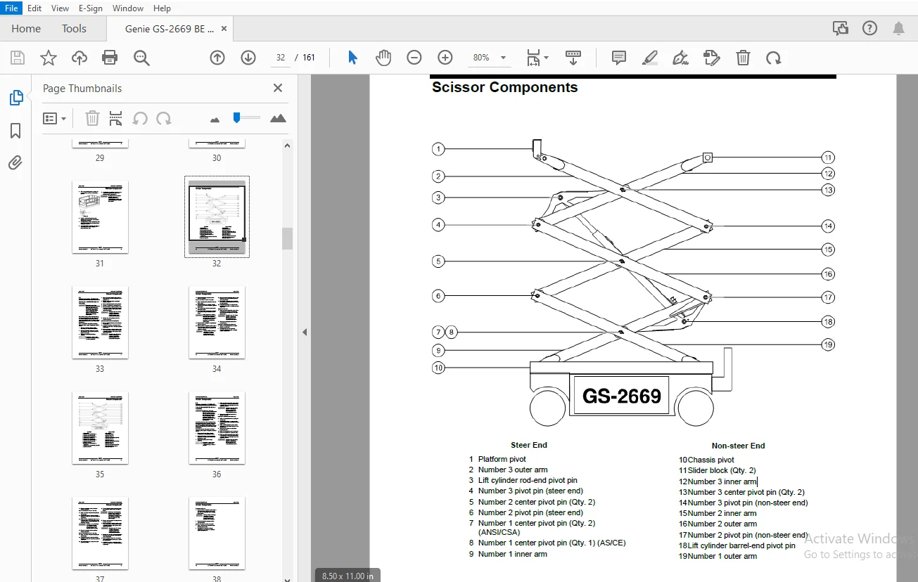
Front Cover......................................................................................................  1
Important Information............................................................................................  2
Find a Manual for this Model.....................................................................................  2
Revision History.................................................................................................  3
Serial Number Legend.............................................................................................  4
General Safety Rules.............................................................................................  5
Table of Contents................................................................................................  7
Specifications................................................................................................... 13
	Machine Specifications....................................................................................... 13
	Performance Specifications................................................................................... 14
	Hydraulic Oil Specifications................................................................................. 14
	Hydraulic Component Specifications........................................................................... 17
	Manifold Component Specifications............................................................................ 17
	Battery Specifications....................................................................................... 18
	Machine Component Weights.................................................................................... 18
	Kohler KD350 Engine Specifications........................................................................... 19
	Hydraulic Hose and Fitting Torque Specifications............................................................. 20
	Torque Procedure............................................................................................. 21
Repair Procedures................................................................................................ 23
	Introduction................................................................................................. 23
	Platform Controls............................................................................................ 25
		1-1 Circuit Board........................................................................................ 26
		1-2 Joystick............................................................................................. 27
		1-3 Platfrom Controls Alarm.............................................................................. 27
		1-4 Platfrom Emergency Stop Button....................................................................... 28
	Platform Components.......................................................................................... 29
		2-1 Platform............................................................................................. 29
		2-2 Platform Extension Deck.............................................................................. 30
	Scissor Components........................................................................................... 32
		3-1 Scissor Assembly, GS-2669 BE......................................................................... 33
		3-2 Scissor Assembly, GS-3369 BE......................................................................... 36
		3-3 Scissor Assembly, GS-4069 BE......................................................................... 40
		3-4 Wear Pads............................................................................................ 43
		3-5 Lift Cylinders....................................................................................... 45
		3-6 Height Angle Sensor.................................................................................. 47
			How to Replace the Height Angle Sensor............................................................... 47
	Engines...................................................................................................... 48
		4-1 Oil Pressure Switch.................................................................................. 48
		How to Replace the Oil Pressure Switch................................................................... 48
			How to Repair the Kohler KD350 Engine................................................................ 48
	Ground Controls.............................................................................................. 49
		5-1 Software Revision Level.............................................................................. 50
		5-2 Machine Setup........................................................................................ 51
		5-3 Auxiliary Platform Lowering.......................................................................... 52
		5-4 Level Sensor - Models without Outriggers............................................................. 52
		5-5 Level Sensor - Models with Outriggers................................................................ 55
		5-6 Service Override Mode................................................................................ 57
	Hydraulic Pump............................................................................................... 59
		6-1 Hydraulic Pump....................................................................................... 59
			How to Test the Hydraulic Pump....................................................................... 59
			How to Remove the Hydraulic Pump..................................................................... 59
			How to Calibrate the Hydraulic Pump.................................................................. 60
	Manifolds.................................................................................................... 63
		7-1 Function Manifold Components......................................................................... 63
			Function Manifold Components - Models with Proportional Relief (from serial number GS6916F-10015).... 64
		7-2 Valve Adjustments - Function Manifold................................................................ 67
			How to Adjust the System Relief Valve................................................................ 67
			How to Adjust the Oscillate Relief Valve............................................................. 69
			How to Adjust the Steer Relief Valve................................................................. 71
			How to Adjust the Platform Up Relief Valve - Models with Platform Overload........................... 73
		7-3 Outrigger Manifold Components........................................................................ 83
		7-4 Valve Coils.......................................................................................... 84
	Fuel and Hydraulic Tanks..................................................................................... 86
		8-1 Fuel Tank............................................................................................ 86
		8-2 Hydraulic Tank....................................................................................... 87
	Steer Axle Components........................................................................................ 88
		9-1 Yoke Assembly........................................................................................ 88
		9-2 Steer Cylinder....................................................................................... 90
		9-3 Tie Rod.............................................................................................. 90
		9-4 Oscillate Cylinder................................................................................... 91
		9-5 Oscillate Hoses...................................................................................... 91
		9-6 Steer Angle Sensor................................................................................... 93
	Non-steer Axle Components.................................................................................... 98
		10-1 Drive Motors........................................................................................ 98
		10-2 Drive Hub........................................................................................... 99
	Outrigger Components.........................................................................................100
		11-1 Outrigger Cylinder..................................................................................100
		11-2 Outrigger Calibration...............................................................................101
	Platform Overload Components.................................................................................103
		12-1 How to Calibrate the Platform Overload System.......................................................103
		12-2 Platform Overload Recovery..........................................................................105
		12-3 Down Limit Height...................................................................................107
			How to Calibrate the Down Limit Height...............................................................107
	Battery Charger..............................................................................................108
		13-1 Battery Charger.....................................................................................108
Fault Codes......................................................................................................110
	Introduction.................................................................................................110
	Platform Overload Fault Codes................................................................................113
	GCON I/O Map.................................................................................................118
	Operation Indicator Codes (OIC)..............................................................................120
	Diagnostic Trouble Codes (DTC)...............................................................................120
	Troubleshooting "HXXX" and "PXXX" Faults.....................................................................121
	Fault Inspection Procedure...................................................................................122
	Type "HXXX" Faults...........................................................................................124
	Type "PXXX" Faults...........................................................................................127
	Type "UXXX" Faults...........................................................................................130
	Type "FXXX" Faults...........................................................................................132
	Type "CXXX" Faults...........................................................................................135
Schematics.......................................................................................................137
	Introduction.................................................................................................137
	Electrical Component and Wire Color Legends..................................................................138
	Hydraulic Component Legend...................................................................................142
	Electrical Symbols Legend....................................................................................143
	Hydraulic Symbols Legend.....................................................................................144
	Limit Switch Legend..........................................................................................145
	Charger Interlock............................................................................................146
	Control Boxes and Options....................................................................................147
		Contactor Box Layout, All Models.........................................................................148
		Ground Control Box Layout................................................................................149
		Platform Control Box Layout, All Models..................................................................152
		Schematic, Generator Option GS-69 BE.....................................................................153
	Electrical Schematics........................................................................................155
		Electrical Schematic 1, GS-69 BE.........................................................................156
		Electrical Schematic 2, GS-69 BE.........................................................................157
	Hydraulic Schematics.........................................................................................159
		Hydraulic Schematic, GS-69 BE............................................................................160
Back Cover.......................................................................................................161
S.S 04/24