Trusted Business
Verified & Licensed
Virus Free Files
100% Safe Downloads
Secure Payment
SSL Protected
Instant Delivery
Available Immediately
Genie GS-2669 DC GS-3369 DC GS-4069 DC Service and Repair Manual – PDF
$26.95
Genie GS-2669 DC GS-3369 DC GS-4069 DC Service and Repair Manual 1272220 – PDF DOWNLOAD
Instant PDF Download
Available immediately
Save to Your Device
Download & keep forever
Antivirus Scanned
100% virus-free
Trusted Worldwide
175,000+ customers
Description
Genie GS-2669 DC GS-3369 DC GS-4069 DC Service and Repair Manual 1272220 – PDF DOWNLOAD
Language : English
Pages : 177
Downloadable : Yes
File Type : PDF
Table of Contents:
Genie GS-2669 DC GS-3369 DC GS-4069 DC Service and Repair Manual 1272220 – PDF DOWNLOAD
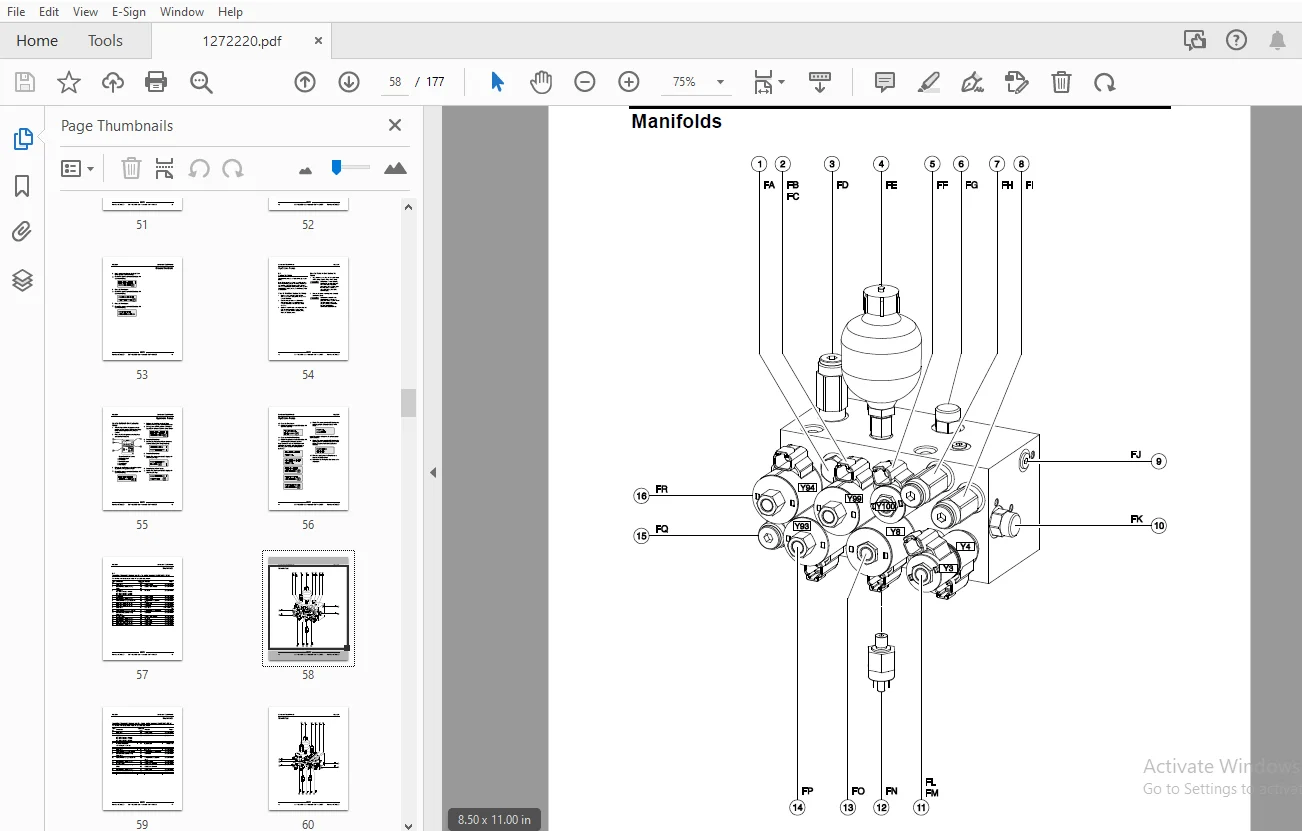
Front Cover.....................................................................................................................................  1
Important Information...........................................................................................................................  2
Find a Manual for this Model....................................................................................................................  2
Revision History................................................................................................................................  3
Serial Number Legend............................................................................................................................  4
General Safety Rules............................................................................................................................  5
Table of Contents...............................................................................................................................  7
Specifications.................................................................................................................................. 13
	Machine Specifications...................................................................................................................... 13
	Performance Specifications.................................................................................................................. 13
	Hydraulic Oil Specifications................................................................................................................ 14
	Hydraulic Component Specifications.......................................................................................................... 16
	Manifold Component Specifications........................................................................................................... 16
	Battery Specifications...................................................................................................................... 16
	Hydraulic Hose and Fitting Torque Specifications............................................................................................ 17
	Torque Procedure............................................................................................................................ 18
Repair Procedures............................................................................................................................... 20
	Introduction................................................................................................................................ 20
	Platform Controls........................................................................................................................... 22
		1-1 Circuit Board....................................................................................................................... 23
		1-2 Joystick............................................................................................................................ 24
		1-3 Platfrom Controls Alarm............................................................................................................. 25
		1-4 Platfrom Emergency Stop Button...................................................................................................... 25
	Platform Components......................................................................................................................... 26
		2-1 Platform............................................................................................................................ 26
		2-2 Platform Extension Deck............................................................................................................. 27
	Scissor Components.......................................................................................................................... 29
		3-1 Scissor Assembly, GS-2669 DC........................................................................................................ 30
		3-2 Scissor Assembly, GS-3369 DC........................................................................................................ 33
		3-3 Scissor Assembly, GS-4069 DC........................................................................................................ 37
		3-4 Wear Pads........................................................................................................................... 40
		3-5 Lift Cylinders...................................................................................................................... 42
	Ground Controls............................................................................................................................. 44
		4-1 Software Revision Level............................................................................................................. 45
		4-2 Machine Setup....................................................................................................................... 46
		4-3 Auxiliary Platform Lowering......................................................................................................... 47
		4-4 Level Sensor - Models without Outriggers............................................................................................ 47
		4-5 Level Sensor - Models with Outriggers............................................................................................... 50
		4-6 Service Override Mode............................................................................................................... 52
	Hydraulic Pump.............................................................................................................................. 54
		5-1 Hydraulic Pump...................................................................................................................... 54
			How to Test the Hydraulic Pump...................................................................................................... 54
			How to Remove the Hydraulic Pump.................................................................................................... 54
			How to Calibrate the Hydraulic Pump................................................................................................. 55
	Manifolds................................................................................................................................... 57
		6-1 Function Manifold Components........................................................................................................ 57
		6-1a Function Manifold Components....................................................................................................... 58
		6-2 Valve Adjustments - Function Manifold............................................................................................... 61
			How to Adjust the System Relief Valve............................................................................................... 61
			How to Adjust the Oscillate Relief Valve............................................................................................ 63
			How to Adjust the Steer Relief Valve................................................................................................ 65
			How to Adjust the Platform Up Relief Valve - Models with Platform Overload.......................................................... 67
			How to Adjust the Platform Up Relief Valve - Models without Platform Overload....................................................... 76
		6-3 Outrigger Manifold Components....................................................................................................... 79
		6-4 Valve Coils......................................................................................................................... 80
	Hydraulic Tank.............................................................................................................................. 82
		7-1 Hydraulic Tank...................................................................................................................... 82
	Steer Axle Components....................................................................................................................... 83
		8-1 Yoke Assembly....................................................................................................................... 83
		8-2 Steer Cylinder...................................................................................................................... 85
		8-3 Tie Rod............................................................................................................................. 85
		8-4 Oscillate Cylinder.................................................................................................................. 86
		8-5 Oscillate Hoses..................................................................................................................... 86
		8-6 Steer Angle Sensor.................................................................................................................. 88
	Non-steer Axle Components................................................................................................................... 92
		9-1 Drive Motors........................................................................................................................ 92
		9-2 Drive Hub........................................................................................................................... 94
	Outrigger Components........................................................................................................................ 95
		10-1 Outrigger Cylinder................................................................................................................. 95
		10-2 Outrigger Calibration.............................................................................................................. 96
	Platform Overload Components................................................................................................................ 98
		11-1 Platform Overload System........................................................................................................... 98
		11-2 Platform Overload Recovery.........................................................................................................102
Fault Codes.....................................................................................................................................104
	Introduction................................................................................................................................104
	GCON I/O Map................................................................................................................................107
	Operation Indicator Codes (OIC).............................................................................................................109
	Diagnostic Trouble Codes (DTC)..............................................................................................................109
	Troubleshooting "HXXX" and "PXXX" Faults....................................................................................................110
	Fault Inspection Procedure..................................................................................................................111
	Type "HXXX" Faults..........................................................................................................................113
	Type "PXXX" Faults..........................................................................................................................116
	Type "UXXX" Faults..........................................................................................................................118
	Type "FXXX" Faults..........................................................................................................................120
	Type "CXXX" Faults..........................................................................................................................123
Schematics......................................................................................................................................125
	Introduction................................................................................................................................125
	Electrical Schematic Abbreviations and Wire Color Legends...................................................................................126
	Hydraulic Component Legend..................................................................................................................129
	Electrical Symbols Legend...................................................................................................................130
	Hydraulic Symbols Legend....................................................................................................................131
	Limit Switch Legend.........................................................................................................................132
	Fuse, Ground and Platform Control Boxes.....................................................................................................133
		Fuse Box Layout, All Models.............................................................................................................134
		Ground Control Box Layout, All Models...................................................................................................135
		Platform Control Box Layout, Models with 2 Speed Lift...................................................................................138
		Control Box Layout, Models with Proportional Lift.......................................................................................139
	Electrical Schematics - ANSI / CSA..........................................................................................................141
		Electrical Schematic, GS-2669 DC and GS-3369 DC with 2 Speed Lift, (ANSI / CSA) (to serial number GS6915-6388)..........................142
		Electrical Schematic, GS-2669 DC and GS-3369 DC with Proportional Lift, (ANSI / CSA) (from serial number GS6915-6389 to GS6915-7719)....143
		Electrical Schematic, GS-2669 DC and GS-3369 DC with Proportional Lift, (ANSI / CSA) (from serial number GS6915-7720)...................146
		Electrical Schematic, GS-4069 DC with 2 Speed Lift, (ANSI / CSA) (to serial number GS6915-6388).........................................147
		Electrical Schematic, GS-4069 DC with Proportional Lift, (ANSI / CSA) (from serial number GS6915-7720)..................................150
		Electrical Schematic, GS-4069 DC with Proportional Lift, (ANSI / CSA) (from serial number GS6915-6389 to GS6915-7719)...................150
	Electrical Schematics - AS / CE.............................................................................................................153
		Electrical Schematic, GS-2669 DC and GS-3369 DC with 2 Speed Lift, (AS / CE) (to serial number GS6915-6388).............................154
		Electrical Schematic, GS-2669 DC and GS-3369 DC with Proportional Lift, (AS / CE) (from serial number GS6915-6389 to GS6915-7719).......155
		Electrical Schematic, GS-2669 DC and GS-3369 DC with Proportional Lift, (AS / CE) (from serial number GS6915-7720)......................158
		Electrical Schematic, GS-4069 DC with 2 Speed Lift, (AS / CE) (to serial number GS6915-6388)............................................159
		Electrical Schematic, GS-4069 DC with Proportional Lift, (AS / CE) (from serial number GS6915-6389 to GS6915-7719)......................162
		Electrical Schematic, GS-4069 DC with Proportional Lift, (AS / CE) (from serial number GS6915-7720).....................................163
	Hydraulic Schematics........................................................................................................................165
		Hydraulic Schematic, GS-2669 DC and GS-3369 DC with 2 Speed Lift (to serial number GS6915-6388).........................................166
		Hydraulic Schematic, GS-2669 DC and GS-3369 DC with Proportional Lift (from serial number GS6915-6389)..................................167
		Hydraulic Schematic, GS-4069 DC with 2 Speed Lift (to serial number GS6915-6388)........................................................170
		Hydraulic Schematic, GS-4069 DC with Proportional Lift (from serial number GS6915-6389).................................................171
		Hydraulic Schematic, GS-2669 DC and GS-3369 DC with 2 Speed Lift (to serial number GS6915-6388).........................................174
		Hydraulic Schematic, GS-2669 DC and GS-3369 DC with Proportional Lift (from serial number GS6915-6389)..................................175
Back Cover......................................................................................................................................177
S.S 04/24