Trusted Business
Verified & Licensed
Virus Free Files
100% Safe Downloads
Secure Payment
SSL Protected
Instant Delivery
Available Immediately
Genie GS-2669 IC GS-3369 IC GS-4069 IC Service & Repair Manual – PDF
$26.95
Genie GS-2669 IC GS-3369 IC GS-4069 IC Service & Repair Manual 1306516 – PDF DOWNLOAD
Instant PDF Download
Available immediately
Save to Your Device
Download & keep forever
Antivirus Scanned
100% virus-free
Trusted Worldwide
175,000+ customers
Description
Genie GS-2669 IC GS-3369 IC GS-4069 IC Service & Repair Manual 1306516 – PDF DOWNLOAD
Language : English
Pages : 171
Downloadable : Yes
File Type : PDF
Table of Contents:
Genie GS-2669 IC GS-3369 IC GS-4069 IC Service & Repair Manual 1306516 – PDF DOWNLOAD
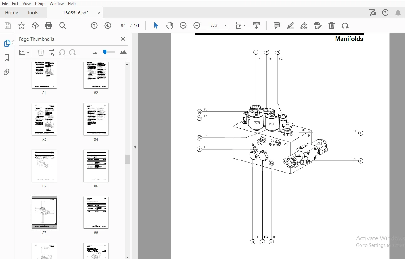
Front Cover...............................................................................  1
Important Information.....................................................................  2
Find a Manual for this Model..............................................................  2
Revision History..........................................................................  3
Serial Number Legend......................................................................  5
General Safety Rules......................................................................  6
Table of Contents.........................................................................  8
Specifications............................................................................ 15
	Machine Specifications................................................................ 15
	Performance Specifications............................................................ 16
	Hydraulic Oil Specifications.......................................................... 16
	Hydraulic Component Specifications.................................................... 20
	Manifold Component Specifications..................................................... 20
	Machine Component Weights............................................................. 21
	GM Engine Models...................................................................... 21
	Kubota D1105-E3B Engine Specifications................................................ 22
	Kubota WG-972 Engine Specifications................................................... 23
	Perkins 403D-11 Engine Specifications................................................. 24
	Hydraulic Hose and Fitting Torque Specifications...................................... 25
	Torque Procedure...................................................................... 26
Repair Procedures......................................................................... 28
	Introduction.......................................................................... 28
	Platform Controls..................................................................... 30
		1-1 Circuit Board................................................................. 30
	Platform Components................................................................... 31
		2-1 Platform...................................................................... 31
		2-2 Platform Extension Deck....................................................... 32
	Scissor Components.................................................................... 34
		3-1 Scissor Assembly, GS-2669 RT.................................................. 35
		3-2 Scissor Assembly, GS-3369 RT.................................................. 38
		3-3 Scissor Assembly, GS-4069 RT.................................................. 42
		3-4 Wear Pads..................................................................... 45
		3-5 Lift Cylinders................................................................ 47
		3-6 Height Angle Sensor........................................................... 49
			How to Replace the Height Angle Sensor........................................ 49
	Kubota D1105 Engine................................................................... 50
		4-1 Timing Adjustment............................................................. 50
		4-2 Glow Plugs.................................................................... 50
		4-3 Engine RPM.................................................................... 51
		4-4 Flex Plate.................................................................... 52
			How to Remove the Flex Plate.................................................. 52
			How to Install the Flex Plate................................................. 52
		4-5 Coolant Temperature and Oil Pressure Switches................................. 53
		4-6 How to Repair the Kubota D1105 Engine......................................... 54
	Kubota WG972 Engine................................................................... 55
		5-1 Timing Adjustment............................................................. 55
		5-2 Carburetor Adjustment......................................................... 55
		5-3 Choke Adjustment.............................................................. 55
		5-4 Flex Plate.................................................................... 55
		5-5 Coolant Temperature and Oil Pressure Switches................................. 55
		5-6 Engine RPM.................................................................... 56
		5-7 How to Repair the Kubota WG972 Engine......................................... 57
	Perkins 403D-11 Engine................................................................ 58
		6-1 Timing Adjustment............................................................. 58
		6-2 Flex Plate.................................................................... 58
		6-3 Coolant Temperature and Oil Pressure Switches................................. 58
		6-4 Engine RPM.................................................................... 59
		6-5 How to Repair the Perkins 403D-11 Engine...................................... 60
	GM .998L Engine....................................................................... 61
		7-1 Timing Adjustment............................................................. 61
		7-2 Flex Plate.................................................................... 61
			How to Remove the Flex Plate.................................................. 61
			How to Install the Flex Plate................................................. 61
	Ground Controls....................................................................... 62
		8-1 Auxiliary Platform Lowering................................................... 62
		8-2 Function Speed Tuning......................................................... 62
			How to Determine the Revision Level........................................... 63
			How to Adjust the Stowed Drive Speed.......................................... 63
			How to Adjust the High Torque Drive Speed..................................... 64
			How to Adjust the Raised Drive Speed.......................................... 65
			How to Adjust the Lift Speed.................................................. 66
		8-3 Software Configuration........................................................ 67
		8-4 Level Sensor - Models without Outriggers...................................... 69
		8-5 Level Sensor - Models with Outriggers......................................... 72
	Hydraulic Pump........................................................................ 76
		9-1 Hydraulic Pump................................................................ 76
			How to Test the Hydraulic Pump................................................ 76
			How to Remove the Hydraulic Pump.............................................. 76
			How to Prime the Pump......................................................... 77
	Manifolds............................................................................. 78
		10-1 Function Manifold Components................................................. 78
		10-2 Valve Adjustments - Function Manifold........................................ 80
			How to Adjust the System Relief Valve......................................... 80
			How to Adjust the Oscillate Relief Valve...................................... 81
			How to Adjust the Platform Up Relief Valve - Models with Platform Overload.... 82
		10-3 Outrigger Manifold Components................................................ 85
		10-4 Traction Manifold Components - View 1........................................ 86
		10-4 Traction Manifold Components - View 2........................................ 88
		10-5 Generator Manifold Components................................................ 90
		10-6 Valve Coils.................................................................. 91
			How to Test the Coils Using the Test System Function.......................... 93
	Fuel and Hydraulic Tanks.............................................................. 94
		11-1 Fuel Tank.................................................................... 94
		11-2 Hydraulic Tank............................................................... 95
	Steer Axle Components................................................................. 96
		12-1 Yoke and Drive Motor......................................................... 96
			How to Remove a Drive Motor................................................... 97
		12-2 Steer Cylinder............................................................... 97
		12-3 Tie Rod...................................................................... 98
		12-4 Oscillate Cylinder........................................................... 98
		12-5 Oscillate Hoses.............................................................. 99
		12-6 Oscillating Axle.............................................................101
	Non-steer Axle Components.............................................................102
		13-1 Drive Motor / Brake Assembly.................................................102
		13-2 Drive Hub....................................................................103
	Outrigger Components..................................................................104
		14-1 Outrigger Cylinder...........................................................104
	Platform Overload Components..........................................................105
		How to Calibrate the Platform Overload System.....................................105
		15-2 Platform Overload Recovery Message...........................................107
		15-3 Down Limit Height............................................................108
			How to Calibrate the Down Limit Height........................................108
Fault Codes...............................................................................109
	Introduction..........................................................................109
	Control System Fault Codes............................................................111
	Platform Overload Fault Codes.........................................................116
		How to Retrieve Engine Fault - Codes GM .998L Models..............................121
Schematics................................................................................127
	Introduction..........................................................................127
	Electrical Component and Wire Color Legends...........................................128
	Hydraulic Component Legend............................................................132
	Electrical Symbols Legend.............................................................134
	Hydraulic Symbols Legend..............................................................135
	Limit Switch Legend...................................................................136
	Electronic Control Module Pin-Out Legend..............................................137
	Ground Control Box....................................................................139
	Platform Control Box - All Models.....................................................140
	GM .998L Engine Fuse and Relay Layout.................................................140
	GM .998L Engine Wire Harness..........................................................142
	Control Panel Circuit Diagram.........................................................143
	Electrical Schematics – ANSI and CSA Models...........................................145
		Electrical Schematic, GS-69 RT  (ANSI / CSA) GM .998L Models......................146
		Electrical Schematic, GS-69 RT  (ANSI / CSA) GM .998L Models......................150
		Electrical Schematic, GS-69 RT (ANSI / CSA) Diesel Models.........................151
		Electrical Schematic, GS-69 RT (ANSI / CSA) Diesel Models.........................155
	Electrical Schematics – AS and CE Models..............................................157
		Electrical Schematic, GS-69 RT  (AS / CE) GM .998L Models.........................158
		Electrical Schematic, GS-69 RT  (AS / CE) GM .998L Models.........................162
		Electrical Schematic, GS-69 RT (AS / CE) Diesel Models............................163
		Electrical Schematic, GS-69 RT (AS / CE) Diesel Models............................167
	Hydraulic Schematics - All Models.....................................................169
		Hydraulic Schematic, GS-69 RT.....................................................170
Back Cover................................................................................171
S.S 04/24