Trusted Business
Verified & Licensed
Virus Free Files
100% Safe Downloads
Secure Payment
SSL Protected
Instant Delivery
Available Immediately
Genie GS-2669 RT GS-3369 RT GS-4069 RT Manual de mantenimiento – PDF
$27.95
Genie GS-2669 RT GS-3369 RT GS-4069 RT Manual de mantenimiento 229753SP – PDF DOWNLOAD
Instant PDF Download
Available immediately
Save to Your Device
Download & keep forever
Antivirus Scanned
100% virus-free
Trusted Worldwide
175,000+ customers
Description
Genie GS-2669 RT GS-3369 RT GS-4069 RT Manual de mantenimiento 229753SP – PDF DOWNLOAD
Language : Spanish
Pages : 233
Downloadable : Yes
File Type : PDF
Table of Contents:
Genie GS-2669 RT GS-3369 RT GS-4069 RT Manual de mantenimiento 229753SP – PDF DOWNLOAD
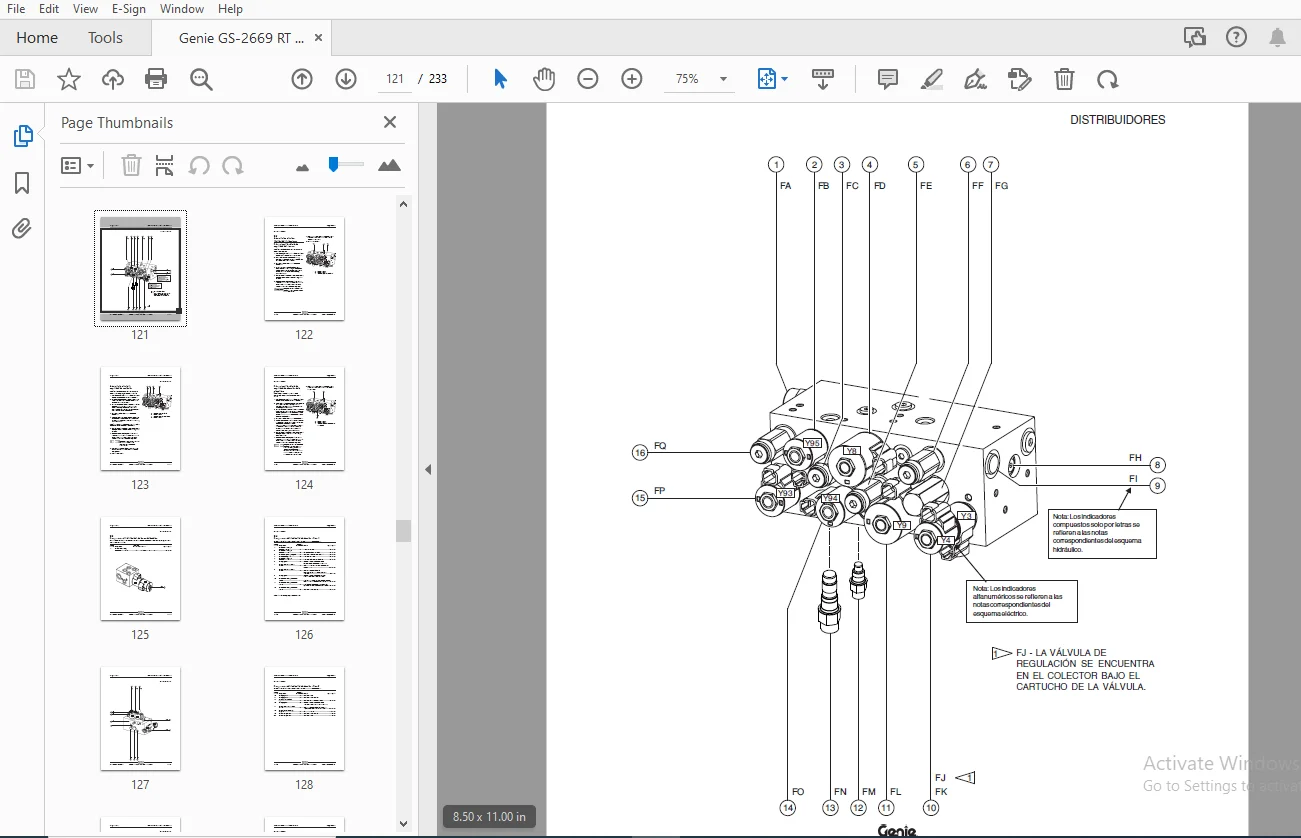
Introduction.....................................................................................  2
Revision History.................................................................................  3
Serial Number Legend.............................................................................  5
Safety Rules.....................................................................................  6
Table of Contents................................................................................  8
Specifications................................................................................... 17
	Machine Specifications....................................................................... 17
	Performance Specifications................................................................... 18
	Hydraulic Specifications..................................................................... 19
	Hydraulic Component Specifications........................................................... 20
	Manifold Component Specifications............................................................ 21
	Kubota D1105 Engine Tier 4................................................................... 22
	Kubota WG972 Engine.......................................................................... 23
	Perkins 403D-11 Engine....................................................................... 25
	Hydraulic Hose and Fitting Torque Specifications............................................. 26
	Torque Procedure............................................................................. 27
	SAE and Metric Fasteners Torque Charts....................................................... 28
Scheduled Maintenance Procedures................................................................. 29
	Introduction................................................................................. 29
	Pre-delivery Preparation..................................................................... 31
	Maintenance Inspection Report................................................................ 33
	Checklist A Prodcedures...................................................................... 35
		A-1 Inspect the Manuals and Decals....................................................... 35
		A-2 Perform Pre-operation Inspection..................................................... 36
		A-3 Perform Function Tests............................................................... 36
		A-4 Perform Engine Maintenance........................................................... 37
		A-5 Test the Oscillate Axle.............................................................. 37
		A-6 Inspect the Engine Air Filter........................................................ 38
		A-7 Perform 30 Day Service............................................................... 39
		A-8 Perform Engine Maintenance - Kubota Models........................................... 39
		A-9 Perform Engine Maintenance - Kubota Models........................................... 40
		A-10 Perform Engine Maintenance - Kubota Models.......................................... 40
		A-11 Replace the Drive Hub Oil........................................................... 41
		A-12 Perform Engine Maintenance - Kubota Models.......................................... 41
		A-13 Drain the Fuel Filter/Water Separator - Kubota Diesel Models........................ 42
		Untitled................................................................................. 43
	Checklist B Prodcedures...................................................................... 44
		B-1 Inspect the Battery.................................................................. 44
		B-2 Inspect the Electrical Wiring........................................................ 45
		B-3 Inspect the Tires, Wheels and Lug Bolt Torque........................................ 46
		B-4 Perform Engine Maintenance - Perkins Models.......................................... 47
		B-5 Test the Key Switch.................................................................. 47
		B-6 Test the Emergency Stop.............................................................. 48
		B-7 Test the Automotive-style Horn....................................................... 48
		B-8 Test the Fuel Select Operation - Kubota Gas/LPG Models............................... 49
		B-9 Test the Drive Brakes................................................................ 50
		B-10 Test the Drive Speed - Stowed Position.............................................. 51
		B-11 Test the Drive Speed - Raised Position.............................................. 52
		B-12 Inspect the Fuel Tank Check Valve Venting System - Gas/LPG Models................... 52
		Untitled................................................................................. 53
		B-14 Perform Hydraulic Oil Analysis...................................................... 54
		B-15 Test the Flashing Beacons (if equipped)............................................. 55
		B-16 Check the Oil Level in the Drive Hubs............................................... 55
		B-17  Perform Engine Maintenance - Kubota Diesel Models.................................. 56
	Checklist C Prodcedures...................................................................... 57
		C-1 Test the Platform Overload System (if equipped)...................................... 57
		C-2 Down Limit Switch Descent Delay (if equipped)........................................ 58
		C-3 Clean the Fuel Tank - Diesel Models.................................................. 59
		C-4 Replace the Hydraulic Tank Breather Cap - Models with Optional Hydraulic Oil......... 60
		C-5 Perform Engine Maintenance - Diesel Models........................................... 61
		C-6 Perform Engine Maintenance - Kubota Diesel Models.................................... 61
	Checklist D Prodcedures...................................................................... 62
		D-1 Check the Scissor Arm Wear Pads...................................................... 62
		D-2 Replace the Hydraulic Tank Return Filter............................................. 62
		D-3 Perform Engine Maintenance - Kubota Models........................................... 63
		D-4 Perform Engine Maintenance - Perkins Models.......................................... 64
		D-5 Perform Engine Maintenance - Kubota Gas / LPG Models................................. 64
		D-6 Replace the Drive Hub Oil............................................................ 65
		D-7 Perfom Engine Maintenance - Kubota Diesel Models..................................... 65
	Checklist E Procedures....................................................................... 66
		E-1 Test or Replace the Hydraulic Oil.................................................... 66
		E-2  Perform Engine Maintenance - Perkins Models......................................... 67
		E-3 Perform Engine Maintenance - Kubota Gas/LPG Models................................... 68
		E-4 Perform Engine Maintenance - Kubota Diesel Models.................................... 68
		E-5 Perform Engine Maintenance - Perkins Models.......................................... 69
		E-6 Perform Engine Maintenance - Kubota Diesel Models.................................... 69
Repair Procedures................................................................................ 71
	Introduction................................................................................. 71
	Platform Controls............................................................................ 72
		1-1  Circuit Boards...................................................................... 72
	Platform Components.......................................................................... 73
		2-1  Platform............................................................................ 73
		2-2  Platform Extension Deck............................................................. 74
	Scissor Components........................................................................... 76
		3-1  Scissor Assembly, GS-2669 RT........................................................ 77
		3-2  Scissor Assembly, GS-3369 RT........................................................ 81
		3-3 Scissor Assembly, GS-4069 RT......................................................... 85
		3-4  Wear Pads........................................................................... 89
		3-5  Lift Cylinder(s).................................................................... 91
	Kubota D1105 Engine.......................................................................... 93
		4-1  Timing Adjustment................................................................... 93
		4-2  Glow Plugs.......................................................................... 93
		4-3  Engine RPM.......................................................................... 94
		4-4  Flex Plate.......................................................................... 94
		4-5  Coolant Temperature and Oil Pressure Switches....................................... 95
	Kubota WG972 Engine.......................................................................... 97
		5-1  Timing Adjustment................................................................... 97
		5-2  Carburetor Adjustment............................................................... 97
		5-3  Choke Adjustment.................................................................... 97
		5-4  Flex Plate.......................................................................... 97
		5-5  Coolant Temperature and Oil Pressure Switches....................................... 97
		5-6  Engine RPM.......................................................................... 98
	Perkins 403D-11 Engine.......................................................................100
		6-1  Engine RPM..........................................................................100
		6-2  Timing Adjustment...................................................................101
		6-3  Flex Plate..........................................................................101
		6-4  Coolant Temperature and Oil Pressure Switches.......................................101
	Ground Controls..............................................................................103
		7-1  Auxiliary Platform Lowering.........................................................103
		7-2  Function Speed Tuning...............................................................103
		7-3  Software Configuration..............................................................108
		7-4  Level Sensor - Models without Outriggers............................................110
		7-5  Level Sensor - Models with Outriggers...............................................113
	Hydraulic Pump...............................................................................118
		8-1  Hydraulic Pump......................................................................118
	Manifolds....................................................................................120
		9-1  Function Manifold Components........................................................120
		9-2  Valve Adjustments - Function Manifold...............................................122
		9-3  Outrigger Manifold Components.......................................................125
		9-4 Traction Manifold Components.........................................................126
		9-5  Generator Manifold Components.......................................................130
		9-6  Valve Coils.........................................................................131
	Fuel and Hydraulic Tanks.....................................................................134
		10-1  Fuel Tank..........................................................................134
		10-2  Hydraulic Tank.....................................................................135
	Steer Axle Components........................................................................136
		11-1  Yoke and Drive Motor...............................................................136
		11-2  Steer Cylinder.....................................................................137
		11-3  Tie Rod............................................................................138
		11-4 Oscillate Cylinder..................................................................138
		11-5 Oscillate Hoses.....................................................................139
	Non-steer Axle Components - Rev A............................................................141
		12-1  Drive Motor and Brake Assembly.....................................................141
		12-2 Drive Hub...........................................................................142
	Outrigger Components.........................................................................143
		13-1  Outrigger Cylinder.................................................................143
	Platform Overload Components.................................................................144
		14-1 Platform Overload System............................................................144
Fault Codes......................................................................................149
	Introduction.................................................................................149
	Fault Code Chart.............................................................................151
Schematics.......................................................................................157
	Introduction.................................................................................157
	Electronic Control Module Pin-Out Legend.....................................................158
	Electrical Schematic Abbreviations, Wire Colos and Hydraulic Component Legends...............159
	Electrical Symbols Legend....................................................................161
	Hydraulic Symbols legend.....................................................................162
	Electrical...................................................................................164
		Control Panel Circuit Diagram............................................................164
		Electrical Schematic, GS-2669 RT and GS-3369 RT, Gas / LPG Models (ANSI / CSA)...........166
		Ground Control Box Layout, GS-2669 RT and GS-3369 RT, Gas / LPG Models (ANSI / CSA)......170
		Platform Control Box Layout, GS-2669 RT and GS-3369 RT, Gas / LPG Models (ANSI / CSA)....171
		Electrical Schematic, GS-2669 RT and GS-3369 RT, Diesel Models (ANSI / CSA)..............174
		Ground Control Box Layout, GS-2669 RT and GS-3369 RT, Diesel Models (ANSI / CSA).........178
		Platform Control Box Layout, GS-2669 RT and GS-336 RT, Diesel Models (ANSI / CSA)........179
		Electrical Schematic, GS-2669 RT and GS-3369 RT, Gas / LPG Models (AS / CE)..............182
		Gorund Control Box Layout, GS-2669 RT and GS-3369 RT, Gas / LPG Models (AS / CE).........186
		Platform Control Box Layout, GS-2669 RT and GS-3369 RT, Gas / LPG Models (AS / CE).......187
		Electrical Schematic, GS-2669 RT and GS-3369 RT, Diesel Models (AS / CE).................190
		Platform Control Box Layout, GS-2669 RT and GS-3369 RT, Diesel Models (AS / CE)..........195
		Electrical Schematic, GS-4069 RT, Gas / LPG Models (ANSI / CSA)..........................198
		Ground Control Box Layout, GS-4069 RT, Gas / LPG Models (ANSI / CSA).....................202
		Platform Control Box Layout, GS-4069 RT, Gas / PLG Models (ANSI / CSA)...................203
		Electrical Schematic, GS-4069 RT, Diesel Models (ANSI / CSA).............................206
		Ground Control Box Layout, GS-4069 RT, Diesel Models (ANSI / CSA)........................210
		Platform Control Box Layout, GS-4069 RT, Diesel Models (ANSI / CSA)......................211
		Electrical Schematic, GS-4069 RT, Gas / LPG Models (AS / CE).............................214
		Ground Control Box Layout, GS-4069 RT, Gas / LPG Models (AS / CE)........................218
		Platform Control Box Layout, GS-4069 RT, Gas / LPG Models (AS / CE)......................219
		Electrical Schematic, GS-4069 RT, Diesel Models (AS / CE)................................222
		Ground Control Box Layout, GS-4069 RT, Diesel Models (AS / CE)...........................226
		Platform Control Box Layout, GS-4069 RT, Diesel Models (AS / CE).........................227
	Hydraulic....................................................................................230
		Hydraulic Schematic, GS-2669 RT and GS-3369 RT...........................................230
		Hydraulic Schematic, GS-4069 RT..........................................................231
S.S 04/24