Genie GS-3384 GS-3390 GS-4390 GS-5390 Service Manual 84793 – PDF
$28.95
Genie GS-3384 GS-3390 GS-4390 GS-5390 Service Manual 84793 – PDF DOWNLOAD
Description
Genie GS-3384 GS-3390 GS-4390 GS-5390 Service Manual 84793 – PDF DOWNLOAD
Language : English
Pages : 277
Downloadable : Yes
File Type : PDF
Table of Contents:
Genie GS-3384 GS-3390 GS-4390 GS-5390 Service Manual 84793 – PDF DOWNLOAD
Introduction
Important Information ii
Serial Number Information ii
Revision History iii
Serial Number Legend v
Section 1 Safety Rules
General Safety Rules vi
Section 2 Specifications
Machine Specifications 2 – 1
Performance Specifications 2 – 2
Hydraulic Specifications 2 – 3
Hydraulic Component Specifications 2 – 4
Manifold Component Specifications 2 – 5
Valve Coil Specifications 2 – 5
Ford LRG-425 EFI Engine 2 – 6
Ford DSG-423 EFI Engine 2 – 7
Deutz F3L 2011 Engine / Deutz D2011L03i Engine 2 – 8
Hydraulic Hose and Fitting Torque Specifications 2 – 10
SAE and Metric Fasteners Torque Charts 2 – 11
Section 3 Scheduled Maintenance Procedures
Introduction 3 – 1
Pre-delivery Preparation Report 3 – 3
Maintenance Inspection Report 3 – 5
Checklist A Procedures
A-1 Inspect the Manuals and Decals 3 – 7
A-2 Perform Pre-operation Inspection 3 – 8
A-3 Perform Function Tests 3 – 8
A-4 Perform Engine Maintenance – Ford models 3 – 9
A-5 Perform Engine Maintenance – Deutz models 3 – 9
Section 3 Scheduled Maintenance Procedures, continued
A-6 Test the Oscillate Axle – GS-90 Models 3 – 10
A-7 Perform 30 Day Service 3 – 11
A-8 Perform Engine Maintenance – Deutz Models 3 – 11
A-9 Perform Engine Maintenance – Ford Models 3 – 11
A-10 Drain the Fuel Filter/ Water Separator – Deutz Models 3 – 12
A-11 Replace the Drive Hub Oil 3 – 13
A-12 Perform Engine Maintenance – Ford Models 3 – 13
Checklist B Procedures
B-1 Inspect the Battery 3 – 14
B-2 Inspect the Electrical Wiring 3 – 15
B-3 Inspect the Engine Air Filter 3 – 16
B-4 Check and Adjust the Engine RPM 3 – 17
B-5 Check the Exhaust System 3 – 18
B-6 Confirm the Proper Brake Configuration 3 – 19
B-7 Inspect the Tires, Wheels and Lug Nut Torque 3 – 19
B-8 Check the Drive Hub Oil Level and Fastener Torque 3 – 20
B-9 Test the Key Switch 3 – 20
B-10 Test the Emergency Stop 3 – 21
B-11 Test the Automotive-style Horn 3 – 21
B-12 Test the Fuel Select Operation – Ford Models 3 – 22
B-13 Test the Drive Brakes 3 – 23
B-14 Test the Drive Speed – Stowed Position 3 – 23
B-15 Test the Drive Speed – Raised Position 3 – 24
B-16 Check the Up Limit Switch Drive Cutout and Outriggers – GS-5390 3 – 25
B-17 Perform Hydraulic Oil Analysis 3 – 26
B-18 Inspect the Fuel and Hydraulic Tank Cap Venting Systems 3 – 26
B-19 Replace the Engine Air Filter Element – Ford Models 3 – 27
B-20 Perform Engine Maintenance – Ford Models 3 – 28
Section 3 Scheduled Maintenance Procedures, continued
Checklist C Procedures
C-1 Test the Platform Overload System (if equipped) 3 – 29
C-2 Down Limit Switch Descent Delay (if equipped) 3 – 30
C-3 Replace the Engine Air Filter Element – Duetz Models 3 – 31
C-4 Replace the Fuel Filter/Water Separator – Deutz Models 3 – 32
C-5 Perform Engine Maintenance – Deutz Models 3 – 33
C-6 Replace the Hydraulic Tank Breather Cap –
Models with Optional Hydraulic Oil 3 – 33
C-7 Perform Engine Maintenance – Ford Models 3 – 33
Checklist D Procedures
D-1 Check the Scissor Arm Wear Pads 3 – 34
D-2 Check the Free-wheel Configuration 3 – 35
D-3 Replace the Drive Hub Oil 3 – 36
D-4 Replace the Hydraulic Filters 3 – 36
D-5 Test the Oscillate Axle – GS-90 Models 3 – 38
D-6 Perform Engine Maintenance – Deutz Models 3 – 41
Checklist E Procedures
E-1 Test or Replace the Hydraulic Oil 3 – 42
E-2 Perform Engine Maintenance – Ford Models 3 – 44
E-3 Perform Engine Maintenance – Deutz Models 3 – 45
E-4 Perform Engine Maintenance – Deutz Models 3 – 45
Section 4 Repair Procedures
Introduction 4 – 1
Platform Controls
1-1 Circuit Boards 4 – 2
Platform Components
2-1 Platform 4 – 3
2-2 Platform Extension Deck 4 – 5
Scissor Components
3-1 Scissor Assembly, GS-3384 and GS-3390 4 – 7
3-2 Scissor Assembly, GS-4390 4 – 13
3-3 Scissor Assembly, GS-5390 4 – 21
3-4 Wear Pads 4 – 28
3-5 Lift Cylinder(s) 4 – 30
Engines
4-1 RPM Adjustment 4 – 35
4-2 Engine Fault Codes – Ford Models 4 – 35
4-3 Engine Repair 4 – 35
4-4 Flex Plate 4 – 36
Ground Controls
5-1 Auxiliary Platform Lowering 4 – 41
5-2 Controller Adjustments 4 – 41
5-3 Software Configuration 4 – 52
5-4 Level Sensor – Models without Outriggers 4 – 58
5-5 Level Sensor – Models with Outriggers 4 – 60
5-6 Engine Fault Codes – Ford Models 4 – 65
Hydraulic Pumps
6-1 Lift/Steer Pump 4 – 67
6-2 Drive Pump 4 – 69
Section 4 Repair Procedures, continued
Manifolds
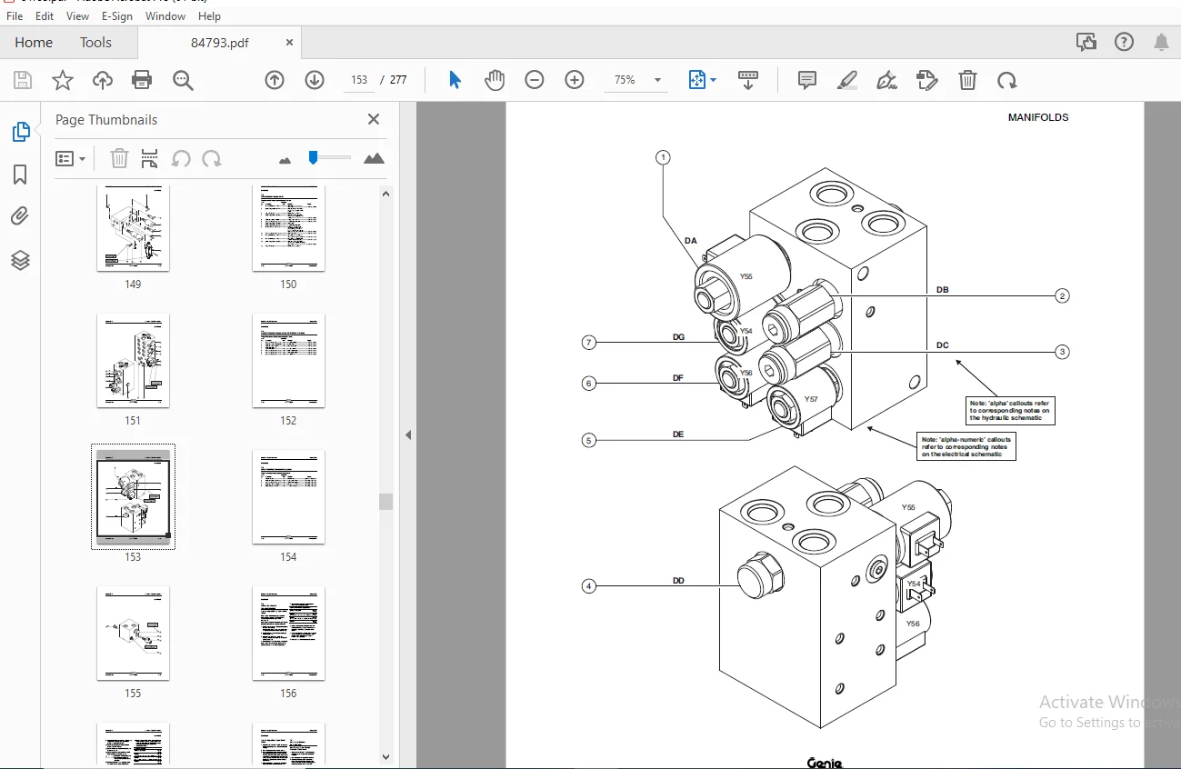
7-1 Function Manifold Components – Models with Outriggers 4 – 72
7-2 Function Manifold Components – Models without Outriggers 4 – 74
7-3 Drive Manifold Components 4 – 76
7-4 Oscillate Manifold Components, GS-90 Models (option) 4 – 78
7-5 Welder Manifold Components, (option) 4 – 80
7-6 Valve Adjustments – Function Manifold 4 – 82
7-7 Valve Adjustments – Drive Manifold 4 – 84
7-8 Generator Manifold Components 4 – 85
7-9 Valve Adjustments – Generator Manifold 4 – 86
7-10 Valve Coils 4 – 87
Fuel and Hydraulic Tanks
8-1 Fuel Tank 4 – 89
8-2 Hydraulic Tank 4 – 90
Steer Axle Components
9-1 Yoke and Drive Motor 4 – 92
9-2 Steer Cylinder 4 – 94
9-3 Oscillating Axle Option (GS-90 models) 4 – 95
Non-steer Axle Components
10-1 Drive Motor and Brake 4 – 96
10-2 Drive Hub 4 – 97
10-3 Oscillating Axle 4 – 97
Outrigger Components
11-1 Outrigger Cylinder 4 – 98
Platform Overload Components
12-1 Platform Overload System 4 – 99
Section 5 Fault Codes
Introduction 5 – 1
Machine Fault Code Chart 5 – 3
Ford LRG-425 ECM Fault Code Chart 5 – 6
Ford DSG-423 ECM Fault Code Chart 5 – 11
Section 6 Schematics
Introduction 6 – 1
Electronic Control Module Layout 6 – 2
Electronic Control Module Pin-Out Legend 6 – 3
Ground Controls Wiring Panel Layout 6 – 4
Ford Engine Relay Layout 6 – 5
Wiring Diagram – Platform Control Box 6 – 6
Limit Switch Legend 6 – 7
Electrical Schematics Abbreviation and Wire Color Legends 6 – 8
Electrical Symbols Legend 6 – 9
Wiring Harness – Ford LRG-425 EFI
(GS-84 models before serial number GS8406-41197)
(GS-90 models before serial number GS9006-43481) 6 – 10
Wiring Harness – Ford DSG-423 EFI
(GS-84 models from serial number GS8406-41197 to GS8407-41311)
(GS-90 models from serial number GS9006-43481 to GS9007-43786) 6 – 12
Wiring Harness – Ford DSG-423 EFI
(GS-84 models after serial number GS8407-41311)
(GS-90 models after serial number GS9007-43786) 6 – 14
Electrical Schematic – ANSI Models with Ford Power
(GS-84 models from serial number GS8406-40833 to GS8406-41196)
(GS-90 models from serial number GS9006-42686 to GS9006-43480) 6 – 16
Electrical Schematic – ANSI Models with Ford Power
(GS-84 models from serial number GS8406-41197 to GS8407-41311)
(GS-90 models from serial number GS9006-43481 to GS9007-43786) 6 – 20
Section 6 Schematics, continued
Electrical Schematic – ANSI Models with Ford Power
(GS-84 models after serial number GS8407-41311)
(GS-90 models from serial number GS9007-43787 to GS9012-48127) 6 – 24
Electrical Schematic – ANSI Models with Ford Power
(GS-84 models after serial number GS8407-41311)
(GS-90 models after serial number GS9012-48127) 6 – 28
Electrical Schematic – CE Models with Ford Power
(GS-84 models from serial number GS8406-40833 to GS8406-41196)
(GS-90 models from serial number GS9006-42686 to GS9006-43480) 6 – 32
Electrical Schematic – CE Models with Ford Power
(GS-84 models from serial number GS8406-41197 to GS8407-41311)
(GS-90 models from serial number GS9006-43481 to GS9007-43786) 6 – 36
Electrical Schematic – CE Models with Ford Power
(GS-84 models from serial number GS8406-41312 to GS8410-42031)
(GS-90 models from serial number GS9006-43787 to GS9010-47262) 6 – 40
Electrical Schematic – CE Models with Ford Power
(GS-84 models after serial number GS8410-42031)
(GS-90 models from serial number GS9010-47263 to GS9012-48127) 6 – 44
Electrical Schematic – CE Models with Ford Power
(GS-84 models after serial number GS8410-42031)
(GS-90 models after serial number GS9012-48127) 6 – 48
Electrical Schematic – ANSI Models with Deutz Power
(GS-84 models after serial number GS8406-40833)
(GS-90 models from serial number GS9006-42686 to GS9012-48127) 6 – 52
Electrical Schematic – ANSI Models with Deutz Power
(GS-84 models after serial number GS8406-40833)
(GS-90 models after serial number GS9012-48127) 6 – 56
Section 6 Schematics, continued
Electrical Schematic – CE Models with Deutz Power
(GS-84 models from serial number GS8406-40833 to GS8410-42031)
(GS-90 models from serial number GS9006-42686 to GS9010-47262) 6 – 60
Electrical Schematic – CE Models with Deutz Power
(GS-84 models after serial number GS8410-42031)
(GS-90 models from serial number GS9010-47263 to GS9012-48127) 6 – 64
Electrical Schematic – CE Models with Deutz Power
(GS-84 models after serial number GS8410-42031)
(GS-90 models after serial number GS9012-48127) 6 – 68
Wiring Diagram – 12 kW Hydraulic Generator (option) 6 – 72
Hydraulic Schematics Component Call-out Legend 6 – 74
Hydraulic Schematics Symbols Legend 6 – 75
Hydraulic Schematic
(GS-84 models from serial number GS8404-40297 to GS8407-41529)
(GS-90 models from serial number GS9004-41691 to GS9007-45004) 6 – 76
Hydraulic Schematic
(GS-84 models after serial number GS8407-41529)
(GS-90 models after serial number GS9007-45004) 6 – 78
S.S 05/24