Trusted Business
Verified & Licensed
Virus Free Files
100% Safe Downloads
Secure Payment
SSL Protected
Instant Delivery
Available Immediately
Genie Z-45/25 Z-45/25J IC Power Service & Repair Manual 1268548 – PDF
$27.95
Genie Z-45/25 Z-45/25J IC Power Service & Repair Manual 1268548 – PDF DOWNLOAD
Instant PDF Download
Available immediately
Save to Your Device
Download & keep forever
Antivirus Scanned
100% virus-free
Trusted Worldwide
175,000+ customers
Description
Genie Z-45/25 Z-45/25J IC Power Service & Repair Manual 1268548 – PDF DOWNLOAD
Language : English
Pages : 255
Downloadable : Yes
File Type : PDF
Table of Contents:
Genie Z-45/25 Z-45/25J IC Power Service & Repair Manual 1268548 – PDF DOWNLOAD
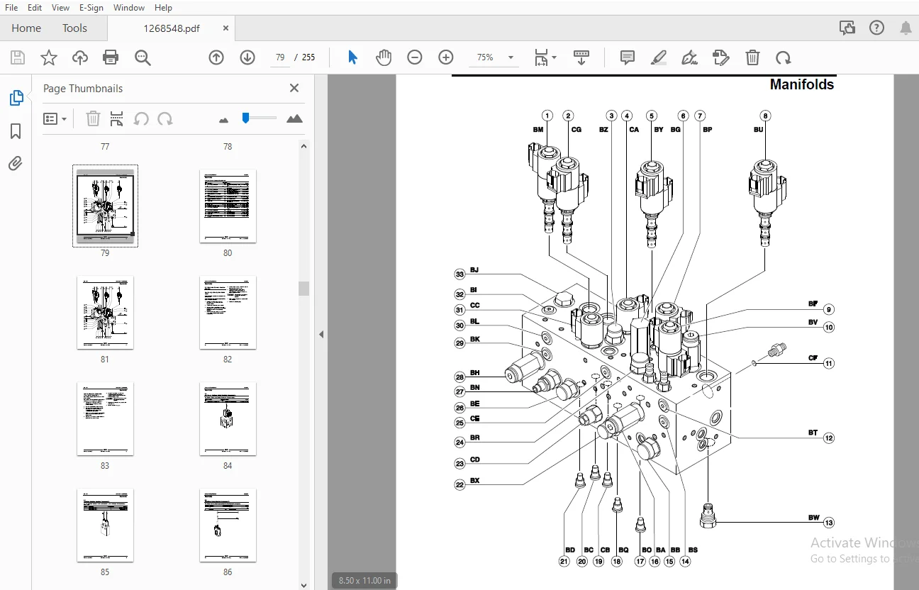
Front Cover........................................................................................................  1
Important Information..............................................................................................  2
Find a Manual for this Model.......................................................................................  2
Revision History...................................................................................................  3
Serial Number Legend...............................................................................................  4
General Safety Rules...............................................................................................  5
Table of Contents..................................................................................................  7
Specifications..................................................................................................... 15
	Machine Specifications......................................................................................... 15
	Performance Specifications..................................................................................... 16
	Hydraulic Specification........................................................................................ 17
	Hydraulic Component Specifications............................................................................. 19
	Ford MSG-425 EFI Engine Specifications......................................................................... 21
	Deutz D2011 L03i Engine Specifications......................................................................... 23
	Deutz D 2.9 L4 Engine Specifications........................................................................... 25
	Perkins 404D-22 Engine Specifications.......................................................................... 27
	Perkins 404F-22 Engine Specifications.......................................................................... 29
	Machine Torque Specifications.................................................................................. 30
	Hydraulic Hose and Fitting Torque Specifications............................................................... 31
	Torque Procedure............................................................................................... 32
	SAE and Metric Fasteners Torque Charts......................................................................... 34
Repair Procedures.................................................................................................. 35
	Introduction................................................................................................... 35
	Platform Controls.............................................................................................. 37
		1-1 ALC-500 Circuit Board.................................................................................. 37
		1-2 Joysticks.............................................................................................. 38
			How to Adjust the Joystick Max-out Setting............................................................. 39
			How to Adjust the Joystick Ramp Rate Setting........................................................... 40
			How to Adjust the Joystick Threshold Setting........................................................... 41
	Platform Components............................................................................................ 43
		2-1 Platform Leveling Slave Cylinder....................................................................... 43
			How to Bleed the Slave Cylinder........................................................................ 44
		2-2 Platform Rotator....................................................................................... 45
		2-3 Platform Overload System............................................................................... 46
	Jib Boom Components............................................................................................ 48
		3-1 Jib Boom............................................................................................... 48
		3-2 Jib Boom Lift Cylinder................................................................................. 49
	Primary Boom Components........................................................................................ 51
		4-1 Cable Track............................................................................................ 51
			How to Remove the Cable Track, Z-45/25................................................................. 51
			How to Remove the Cable Track, Z-45/25J................................................................ 53
			How to Repair the Primary Boom Cable Track............................................................. 55
		4-2 Primary Boom........................................................................................... 55
			How to Disassemble the Primary Boom.................................................................... 57
		4-3 Primary Boom Lift Cylinder............................................................................. 58
		4-4 Primary Boom Extension Cylinder........................................................................ 59
		4-5 Platform Leveling Master Cylinder...................................................................... 60
	Secondary Boom Components...................................................................................... 61
		5-1 Secondary Boom......................................................................................... 62
		5-2 Secondary Boom Lift Cylinders.......................................................................... 67
	Engines........................................................................................................ 69
		6-1 RPM Adjustment - Deutz D2011L03i Models................................................................ 69
		6-2 RPM Adjustment - Perkins 404D-22 Models................................................................ 69
		6-3 Flex Plate............................................................................................. 69
			How to Install the Flex Plate.......................................................................... 71
			How to install the Pump and Bell Housing Assembly...................................................... 72
		6-4 Ford MSG-425 Engine Fault Codes........................................................................ 73
		6-5 Engine Fault Codes - Deutz D 2.9 L4 and Perkins 404F-22 Models......................................... 73
	Hydraulic Pumps................................................................................................ 74
		7-1 Lift/Steer Pump........................................................................................ 74
		7-2 Drive Pump............................................................................................. 75
			How to Prime the Pump.................................................................................. 76
	Manifolds...................................................................................................... 78
		8-1 Function Manifold Components........................................................................... 78
		8-2 Valve Adjustments - Function Manifold.................................................................. 82
			How to Adjust the System Relief Valve.................................................................. 82
			How to Adjust the Secondary Boom Down Relief Valve..................................................... 83
		8-3 Jib Boom / Platform Rotate Manifold Components......................................................... 84
		8-4 Turntable Rotation Manifold Components................................................................. 85
		8-5 Directional Valve Manifold Components.................................................................. 86
			How to Set Up the Directional Valve Linkage............................................................ 87
		8-6 Traction Manifold Components, 2WD...................................................................... 88
		8-7 Valve Adjustments, 2WD Traction Manifold............................................................... 90
		8-8 Traction Manifold Components, 4WD...................................................................... 91
		8-9 Valve Adjustments, 4WD Traction Manifold............................................................... 93
		8-10 Hydraulic Generator Manifold Components, 2.2kW........................................................ 94
		8-11 Valve Coils........................................................................................... 95
			How to Test a Coil Diode............................................................................... 95
	Turntable Rotation Components.................................................................................. 97
		9-1 Turntable Rotation Assembly............................................................................ 97
	Axle Components................................................................................................ 99
		10-1 Hub and Bearings, 2WD Models.......................................................................... 99
			How to Remove the Hub and Bearings..................................................................... 99
			How to Install the Hub and Bearings.................................................................... 99
		10-2 Oscillating Axle Cylinders............................................................................100
Fault Codes........................................................................................................101
	Introduction...................................................................................................101
	Control System Fault Codes.....................................................................................102
		How to Retrieve Control System Fault Codes.................................................................102
		Control System Fault Codes.................................................................................103
	Fault Code Display - Deutz and Perkins Models..................................................................107
		How to Retrieve Active Engine Fault Codes Deutz D 2.9 L4 and Perkins 404F-22 Models........................107
		Fault Code Display - Flashing and Solid LED's - Deutz D 2.9 L4 and Perkins 404F-22 Models..................108
		Soft Key Functions and Icons - Deutz D 2.9 L4 and Perkins 404F-22 Models...................................109
		Main Menu Structure - Deutz D 2.9 L4 Models................................................................110
		Main Menu Structure - Perkins 404F-22 Models...............................................................111
	Deutz D 2.9 L4 Engine Fault Codes..............................................................................112
	Perkins 404F-22 Engine Fault Codes.............................................................................123
	Ford MSG-425 Engine Fault Codes................................................................................125
		How to Retrieve Ford MSG-425 Engine Fault Codes............................................................125
		Ford MSG-425 Engine Fault Codes............................................................................126
Schematics.........................................................................................................131
	Introduction...................................................................................................131
	Electrical Symbol Legend.......................................................................................132
	Hydraulic Symbols Legend.......................................................................................133
	Electrical Component and Wire Color Legends....................................................................134
	Ford Engine Relay Layout.......................................................................................137
	Engine Relay Layout - Deutz D 2.9 L4 and Perkins 404F-22.......................................................138
	Electrical Schematics – Options................................................................................139
		Ford MSG-425 EFI Engine Wire Harness.......................................................................140
		Deutz D 2.9 L4 Engine Wire Harness.........................................................................141
		Perkins 404F-22 Engine Wire Harness........................................................................144
		Electrical Schematic, Options (All Models).................................................................145
		Ground Control Box Terminal Strip Wiring Diagram, Options..................................................148
		Platform Control Box Wiring Diagram, Options...............................................................149
		Wiring Diagram - Battery, Hydraulic Oil and Engine Oil Heater Options......................................152
		Wiring Diagram, 2.2kW Hydraulic Generator..................................................................153
	Hydraulic Schematics...........................................................................................155
		Hydraulic Schematic, 2WD Models............................................................................156
		Hydraulic Schematic, 4WD Models............................................................................157
	Electrical Schematics – ANSI and CSA Models....................................................................159
		Electrical Schematic, Ford MSG-425 EFI Models (ANSI/CSA)...................................................160
		Ground Control Box Terminal Strip Wiring Diagram - Ford MSG-425 EFI Models (ANSI/CSA)......................164
		Ground Control Box Switch Panel Wiring Diagram - Ford MSG-425 EFI Models (ANSI/CSA)........................165
		Platform Control Box Wiring Diagram - Ford MSG-425 EFI Models (ANSI/CSA)...................................168
		Platform Control Box Switch Panel Wiring Diagram - Ford MSG-425 EFI Models (ANSI/CSA)......................169
		Electrical Schematic, Deutz D2011 L03i / Perkins 404D-22 Models (ANSI/CSA).................................172
		Ground Control Box Terminal Strip Wiring Diagram - Deutz D2011 L03i / Perkins 404D-22 Models (ANSI/CSA)....176
		Ground Control Box Switch Panel Wiring Diagram - Deutz D2011 L03i / Perkins 404D-22 Models (ANSI/CSA)......177
		Platform Control Box Wiring Diagram - Deutz D2011 L03i / Perkins 404D-22 Models (ANSI/CSA).................180
		Platform Control Box Switch Panel Wiring Diagram - Deutz D2011 L03i / Perkins 404D-22 Models (ANSI/CSA)....181
	Electrical Schematics – ANSI Models............................................................................183
		Electrical Schematic, Deutz D 2.9 L4 Models (ANSI).........................................................184
		Ground Control Box Terminal Strip Wiring Diagram - Deutz D 2.9 L4 Models (ANSI)............................188
		Ground Control Box Switch Panel Wiring Diagram - Deutz D 2.9 L4 Models (ANSI)..............................189
		Platform Control Box Wiring Diagram - Deutz D 2.9 L4 Models (ANSI).........................................192
		Platform Control Box Switch Panel Wiring Diagram - Deutz D 2.9 L4 Models (ANSI)............................193
		Electrical Schematic,  Perkins 404F-22 Models (ANSI).......................................................196
		Ground Control Box Terminal Strip Wiring Diagram - Perkins 404F-22 Models (ANSI)...........................200
		Ground Control Box Switch Panel Wiring Diagram - Perkins 404F-22 Models (ANSI).............................201
		Platform Control Box Wiring Diagram Perkins 404F-22 Models (ANSI)..........................................204
		Platform Control Box Switch Panel Wiring Diagram - Perkins 404F-22 Models (ANSI)...........................205
	Electrical Schematics – AS Models..............................................................................207
		Electrical Schematic, Ford MSG-425 EFI Models (AS).........................................................208
		Ground Control Box Terminal Strip Wiring Diagram - Ford MSG-425 EFI Models (AS)............................212
		Ground Control Box Switch Panel Wiring Diagram - Ford MSG-425 EFI Models (AS)..............................213
		Platform Control Box Wiring Diagram - Ford MSG-425 EFI Models (AS).........................................216
		Platform Control Box Switch Panel Wiring Diagram - Ford MSG-425 EFI Models (AS)............................217
		Electrical Schematic, Deutz 2011 L03i / Perkins 404D-22 Models (AS)........................................220
		Ground Control Box Terminal Strip Wiring Diagram - Deutz 2011 L03i / Perkins 404D-22 Models (AS)...........224
		Ground Control Box Switch Panel Wiring Diagram - Deutz 2011 L03i / Perkins 404D-22 Models (AS).............225
		Platform Control Box Wiring Diagram - Deutz 2011 L03i / Perkins 404D-22 Models (AS)........................228
		Platform Control Box Switch Panel Wiring Diagram - Deutz 2011 L03i / Perkins 404D-22 Models (AS)...........229
	Electrical Schematics – CE Models..............................................................................231
		Electrical Schematic, Ford MSG-425 EFI Models (CE).........................................................232
		Ground Control Box Terminal Strip Wiring Diagram - Ford MSG-425 EFI Models (CE)............................236
		Ground Control Box Switch Panel Wiring Diagram - Ford MSG-425 EFI Models (CE)..............................237
		Platform Control Box Wiring Diagram - Ford MSG-425 EFI Models (CE).........................................240
		Platform Control Box Switch Panel Wiring Diagram - Ford MSG-425 EFI Models (CE)............................241
		Electrical Schematic, Deutz 2011 L03i / Perkins 404D-22 Models (CE)........................................244
		Ground Control Box Terminal Strip Wiring Diagram - Deutz 2011 L03i / Perkins 404D-22 Models (CE)...........248
		Ground Control Box Switch Panel Wiring Diagram - Deutz 2011 L03i / Perkins 404D-22 Models (CE).............249
		Platform Control Box Wiring Diagram - Deutz 2011 L03i / Perkins 404D-22 Models (CE)........................252
		Platform Control Box Switch Panel Wiring Diagram - Deutz 2011 L03i / Perkins 404D-22 Models (CE)...........253
Back Cover.........................................................................................................255
S.S 05/24