Trusted Business
Verified & Licensed
Virus Free Files
100% Safe Downloads
Secure Payment
SSL Protected
Instant Delivery
Available Immediately
Genie Z-60/34 Service Manual 75861 – PDF DOWNLOAD
$29.95
Genie Z-60/34 Service Manual 75861 – PDF DOWNLOAD
Instant PDF Download
Available immediately
Save to Your Device
Download & keep forever
Antivirus Scanned
100% virus-free
Trusted Worldwide
175,000+ customers
Description
Genie Z-60/34 Service Manual 75861 – PDF DOWNLOAD
Language : English
Pages : 341
Downloadable : Yes
File Type : PDF
Table of Contents:
Genie Z-60/34 Service Manual 75861 – PDF DOWNLOAD
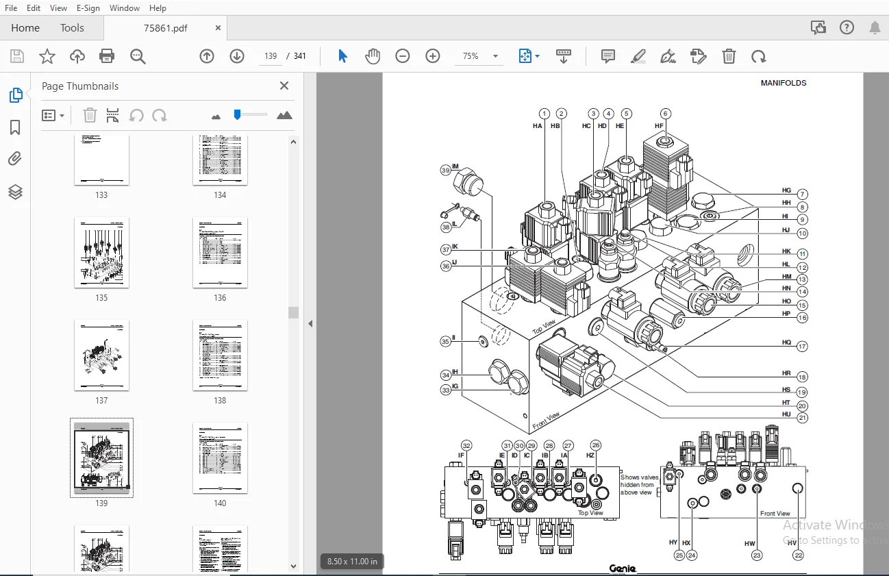
Cover.........................................................................................................  1
Introduction..................................................................................................  2
Revision History
.............................................................................................  3
Serial Number Legend..........................................................................................  5
Safety Rules..................................................................................................  6
Table of Contents.............................................................................................  8
Specifications................................................................................................ 19
	Machine Specifications.................................................................................... 19
	Performance Specifications................................................................................ 20
	Hydraulic Oil Specifications.............................................................................. 21
	Hydraulic Component Specifications........................................................................ 22
	Manifold Components Specifications........................................................................ 24
	Ford LRG-425 EFI Engine................................................................................... 25
	Ford DSG-423 EFI Engine................................................................................... 27
	Ford MSG-425 EFI Engine
.................................................................................. 28
	Deutz F4L 1011F Engine.................................................................................... 30
	Deutz F3L 1011F Engine.................................................................................... 31
	Deutz F3L 2011 Engine / Deutz D2011L03i................................................................... 32
	Perkins 404C-22 Engine.................................................................................... 34
	Machine Torque Specifications............................................................................. 35
	Hydraulic Hose & Fittings Torque.......................................................................... 36
	SAE and Metric Fastener Torque Chart...................................................................... 38
Scheduled Maintenance Procedures.............................................................................. 39
	Pre-Delivery Preparation.................................................................................. 41
	Maintenance Inspection Report............................................................................. 43
	Checklist A Procedures.................................................................................... 45
		A-1  Inspect the Manuals and Decals................................................................... 45
		A-2 Perform Pre-operation Inspection.................................................................. 46
		A-3 Perform Function Tests............................................................................ 46
		A-4  Perform Engine Maintenance- All Models........................................................... 47
		A-5 Perform 30 Day Service............................................................................ 48
		A-6 Check the High Pressure Filter Condition Indicator................................................ 48
		A-7 Perform Engine Maintenance- Deutz and Ford Models................................................. 49
		A-8 Perform Engine Maintenance- Perkins Models........................................................ 50
		A-9 Inspect the Fuel Filter/Water Separator- Deutz Models............................................. 50
		A-10 Perform Engine Maintenance- Ford Models.......................................................... 51
		A-11 Grease the Turntable Rotation Bearing and Rotate Gear............................................ 52
		A-12 Perform Engine Maintenance- Deutz 1011F Models................................................... 52
		A-13  Replace the Drive Hub Oil....................................................................... 53
		A-14  Perform Engine Maintenance - Ford Models........................................................ 54
	Checklist B Procedures.................................................................................... 55
		B-1  Inspect the Battery.............................................................................. 55
		B-2  Inspect the Electrical Wiring.................................................................... 56
		B-3 Inspect the Air Filter............................................................................ 57
		B-4  Test the Key Switch.............................................................................. 58
		B-5  Perform Engine Maintenance - Deutz and Perkins Models............................................ 58
		B-6  Check the Exhaust System......................................................................... 59
		B-7  Check the Oil Cooler and Cooling Fins - Deutz Models............................................. 59
		B-8 Inspect the Tires, Wheels and Lug Nut Torque...................................................... 60
		B-9 Check the Drive Hub Oil Level and Fastener Torque................................................. 61
		B-10 Confirm the Proper Brake Configuration........................................................... 62
		B-11 Test the Engine Idle Select...................................................................... 63
		B-12 Test the Fuel Select Operation - Ford Models..................................................... 63
		B-13 Test the Ground Control Override................................................................. 64
		B-14 Check the Directional Valve Linkage.............................................................. 65
		B-15
 Test the Platform Self-leveling................................................................. 65
		B-16
  Test the Drive Brakes.......................................................................... 66
		B-17
  Test the Drive Speed - Stowed Position......................................................... 66
		B-18
  Test the Drive Speed - Raised or Extended Position............................................. 67
		B-19  Perform Hydraulic Oil Analysis.................................................................. 68
		B-20
 Test the Alarm Package (if equipped) and the Descent Alarm...................................... 68
		B-21
 Inspect the Fuel and Hydraulic Tank Cap Venting Systems......................................... 69
		B-22
  Perform Engine Maintenance - Ford Models....................................................... 70
	Checklist C Procedures.................................................................................... 71
		C-1  Perform Engine Maintenance - Deutz and Perkins Models............................................ 71
		C-2  Grease the Platform Overload Mechanism (if equipped)............................................. 72
		C-3  Test the Platform Overload Mechanism (if equipped)............................................... 72
		C-4 Replace the Engine Air Filter Element- Deutz and Perkins Models................................... 75
		C-5 Replace the In-line Fuel Strainer- Deutz Models................................................... 75
		C-6 Check and Adjust the Engine RPM .................................................................. 76
		C-7 Perform Engine Maintenance- Ford Models........................................................... 77
	Checklist D Procedures.................................................................................... 79
		D-1 Check the Boom Wear Pads.......................................................................... 79
		D-2 Check the Turntable Rotation Bearing Bolts........................................................ 80
		D-3 Check the Free-wheel Configuration
............................................................... 81
		D-4 Replace the Drive Hub Oil......................................................................... 82
		D-5 Perform Engine Maintenance- Deutz and Perkins Models.............................................. 84
		D-6 Replace the Hydraulic Filter Elements............................................................. 85
		D-7 Inspect for Turntable Bearing Wear................................................................ 86
	Checklist E Procedures.................................................................................... 88
		E-1  Test or Replace the Hydraulic Oil................................................................ 88
		E-2  Grease the Steer Axle Wheel Bearings, 2WD Models................................................. 90
		E-3 Perform Engine Maintenance- Deutz 1011F and Perkins Models........................................ 91
		E-4
  Perform Engine Maintenance - Deutz 1011F and Perkins Models..................................... 92
		E-5
 Perform Engine Maintenance- Ford Models.......................................................... 93
		E-6 Perform Engine Maintenance- Deutz 2011 Models..................................................... 93
		E-7 Perform Engine Maintenance- Deutz 2011 Models..................................................... 94
		E-8 Perform Engine Maintenance- Deutz 2011 Models..................................................... 94
Repair Procedures............................................................................................. 95
	Introduction.............................................................................................. 95
	Platform Controls......................................................................................... 96
		1-1  ALC-500 Circuit Board............................................................................ 96
		1-2  Joysticks........................................................................................ 97
	Platform Components.......................................................................................101
		2-1 Platform..........................................................................................101
		2-2  Platform Leveling Slave Cylinder.................................................................102
		2-3  Platform Rotator.................................................................................103
		2-4 Platform Overload System..........................................................................104
	Jib Boom Components.......................................................................................108
		3-1  Jib Boom.........................................................................................108
		3-2  Jib Boom Lift Cylinder...........................................................................109
	Primary Boom Components...................................................................................111
		4-1  Cable Track......................................................................................111
		4-2  Primary Boom.....................................................................................113
		4-3  Primary Boom Lift Cylinder.......................................................................115
		4-4  Primary Boom Extension Cylinder..................................................................116
		4-5  Platform Leveling Master Cylinder................................................................119
	Secondary Boom Components.................................................................................120
		5-1  Secondary Boom...................................................................................120
		5-2  Secondary Boom Lift Cylinders....................................................................124
	Engines...................................................................................................125
		6-1  RPM Adjustment...................................................................................125
		6-2  Flex Plate.......................................................................................125
		6-3  Engine Fault Codes - Ford Models.................................................................129
	Hydraulic Pumps...........................................................................................130
		7-1  Function Pump....................................................................................130
		7-2  Drive Pump.......................................................................................131
	Manifolds.................................................................................................134
		8-1  Function Manifold - View 1 (before serial number 4461)...........................................136
		8-2  Function Manifold - View 2 (before serial number 4461)...........................................138
		8-3  Function Manifold  (from
 serial number 4461)....................................................140
		8-4  Valve Adjustments - Function Manifold............................................................142
		8-5 Jib Boom/Platform Rotate Manifold Components (before serial number 4461)..........................144
		8-6 Jib Boom/Platform Rotate Manifold Components (from serial number 4461 to serial number 10425)
....145
		8-7  Jib Boom/Platform Rotate Manifold (from serial number 10426 to serial number 11003
).............146
		8-8 Jib Boom/Platform Rotate Manifold (from serial number 11004 to serial number 11477) ..............147
		8-9 Jib Boom/Platform Rotate Manifold (from serial number 11478)
.....................................148
		8-10 Brake/Two Speed Manifold (before serial number 4461).............................................150
		8-11 Brake / Two-Speed Manifold (from serial number 4461 )............................................151
		8-12 2WD Traction  Manifold (before serial number 4551)...............................................152
		8-13 2WD Traction  Manifold (from serial number 4551).................................................154
		8-14 4WD Traction Manifold (before serial number 10154) ..............................................156
		8-15 4WD Traction Manifold (from serial number 10154) ................................................158
		8-16 Valve Adjustments, Traction Manifolds............................................................160
		8-17 Directional Valve Manifold Components............................................................161
		8-18 Directional Valve Linkage - How to Set Up the Oscillate Directional Valve........................162
		8-19 Valve Adjustments - Oscillate Relief Valve.......................................................163
		8-20 Turntable Rotation Manifold......................................................................164
		8-21 Oil Diverter Manifold Components (welder option).................................................165
		8-22 Valve Coils......................................................................................166
	Turntable Rotation Components.............................................................................168
		9-1 Turntable Rotation Assembly.......................................................................168
	Axle Components...........................................................................................169
		10-1 Hub and Bearings, 2WD Models.....................................................................169
		10-2 Oscillate Cylinders..............................................................................170
	Generators................................................................................................171
		11-1 Valve Adjustment - Hydraulic Generator...........................................................  0
Fault Codes...................................................................................................173
	Introduction..............................................................................................173
	Fault Code Chart - Control System.........................................................................174
	Fault Code Chart - Ford LRG-425 EFI Engine................................................................178
	Fault Code Chart - Ford DSG-423 EFI Engine................................................................184
	Fault Code Chart - Ford MSG-425 EFI Engine ...............................................................188
Schematics....................................................................................................195
	Introduction..............................................................................................195
	Wire Connector Legend.....................................................................................196
	Electrical Symbols Legend.................................................................................197
	Hydraulic Symbols Legend..................................................................................198
	Electrical Abbreviations Legend
..........................................................................199
	Ford DSG-423 Engine Relay Layout..........................................................................202
	Ford MSG-425 Engine Relay Layout
.........................................................................202
	Diesel Models.............................................................................................204
		Diesel Electrical Schematic (before serial number 4496)...............................................204
		Diesel Electrical Schematic (from serial number 4496 to 5325) ........................................208
		Diesel Electrical Schematic (from serial number 5326 to 9798).........................................212
		Diesel Electrical Schematic (from serial number 9799 to 10387)
.......................................216
		Diesel Electrical Schematic,  ANSI / CSA  (from serial number 10388) .................................220
		Diesel Electrical Schematic,
 CE (from serial number 9799 to 10387) ..................................224
		Diesel Electrical Schematic, CE  (from serial number 10388) ..........................................228
		Diesel Ground Control Box Wiring Diagram (before serial number 5716)
.................................232
		Diesel Ground Control Box Wiring Diagram (from serial number 5716 to 9798
)...........................233
		Diesel Ground Control Box Wiring Diagram (from serial number 9799)....................................236
		Diesel Platform Countrol Box Wiring Diagram (before serial number 7227)
..............................238
		Diesel Platform Countrol Box Wiring Diagram (from serial number 7227 to 9065
) .......................239
		Diesel Platform Countrol Box Wiring Diagram (from serial number 9066 to 9696
) .......................242
		Diesel Platform Countrol Box Wiring Diagram (from
 serial number 9697) ...............................243
	Ford Models...............................................................................................246
		Ford Electrical Schematic (before serial number 4546)
................................................246
		Ford Electrical Schematic (from serial number 4546 to 5715)
..........................................250
		Ford Electrical Schematic (from serial number 5716 to 6315
) .........................................254
		Ford Electrical Schematic (from serial number 6316 to 7226
) .........................................258
		Ford Electrical Schematic (from serial number 7227 to 10387
) ........................................262
		Ford Electrical Schematic, ANSI / CSA  (from serial number 10388 to 11788 ) ..........................266
		Ford Electrical Schematic, ANSI / CSA  (from serial number
11789) ...................................270
		Ford Electrical Schematic, CE (from serial number 10388 to 11788 ) ...................................274
		Ford Electrical Schematic, CE (from serial number  11789) ............................................278
		Ford Ground Control Box Wiring Diagram (before serial number 4545)
...................................282
		Ford Ground Control Box Wiring Diagram (from serial number 4546 to 5715)..............................283
		Ford Ground Control Box Wiring Diagram (from serial number 5716 to 7226
).............................286
		Ford Ground Control Box Wiring Diagram (from serial number 7227 to 9798
).............................287
		Ford Ground Control Box Wiring Diagram (from serial number 9799)
.....................................290
		Ford Platform Control Box Wiring Diagram (before serial number 7227)
.................................291
		Ford Platform Control Box Wiring Diagram (from serial number 7227 to 9065
)...........................294
		Ford Platform Control Box Wiring Diagram (from serial number 9066 to 9798
)...........................295
		Ford Platform Control Box Wiring Diagram (from  serial number 9799 to 11788 ).........................298
		Ford Platform Control Box Wiring Diagram (from  serial number
11789).................................299
	Engine Wire Harness, Ford LRG-425 EFI Models
.............................................................302
	Engine Wire Harness, Ford DSG-423 EFI Models (before serial number 6810)
.................................303
	Engine Wire Harness, Ford DSG-423 EFI Models (from  serial number 6810 to 11788)..........................306
	Engine Wire Harness, Ford MSG-425 EFI Models (from serial number 11789
...................................307
	Electrical Schematic- CTE Option (before serial number 9697)
.............................................310
	Electrical Schematic - CTE Option (from serial number 9697)
..............................................311
	Joystick Connector Diagram
...............................................................................314
	Hydraulic Generator Options (from serial number 10283)
 ..................................................315
	Electrical Schematic - Welder Option......................................................................318
	Hydraulic Schematic- Welder Option
.......................................................................319
	Hydraulic Schematics......................................................................................322
		Hydraulic Schematic - 2WD Models (before serial number 4461)..........................................322
		Hydraulic Schematic - 2WD Models (from serial number 4461 to 10282)
..................................323
		Hydraulic Schematic - 2WD Models (from  serial number 10283 to serial number 11003
)..................326
		Hydraulic Schematic - 2WD Models (from serial number 11004 to 11477 ) ................................327
		Hydraulic Schematic - 2WD Models (from serial number
11478) .........................................329
		Hydraulic Schematic - 4WD Models (before serial number 4461)..........................................332
		Hydraulic Schematic - 4WD Models (from serial number 4461 to 10282)
..................................333
		Hydraulic Schematic - 4WD Models (from serial number 10283 to serial number 11003
)...................336
		Hydraulic Schematic - 4WD Models (from serial number 11004 to 11477)..................................337
		Hydraulic Schematic - 4WD Models (from serial number 11478
) .........................................339
Back Cover....................................................................................................341
S.S 05/24