Trusted Business
Verified & Licensed
Virus Free Files
100% Safe Downloads
Secure Payment
SSL Protected
Instant Delivery
Available Immediately
Genie Z-62/40 Service & Repair Manual 1268555 – PDF DOWNLOAD
$27.95
Genie Z-62/40 Service & Repair Manual 1268555 – PDF DOWNLOAD
Instant PDF Download
Available immediately
Save to Your Device
Download & keep forever
Antivirus Scanned
100% virus-free
Trusted Worldwide
175,000+ customers
Description
Genie Z-62/40 Service & Repair Manual 1268555 – PDF DOWNLOAD
Language : English
Pages : 287
Downloadable : Yes
File Type : PDF
Table of Contents:
Genie Z-62/40 Service & Repair Manual 1268555 – PDF DOWNLOAD
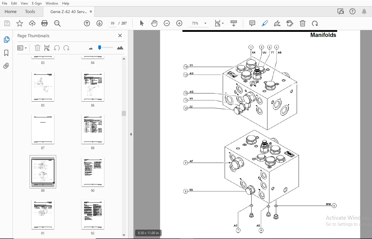
Front Cover.......................................................................................................  1
Important Information.............................................................................................  2
Find a Manual for this Model......................................................................................  2
Revision History..................................................................................................  3
Serial Number Legend..............................................................................................  4
General Safety Rules..............................................................................................  5
Table of Contents.................................................................................................  7
Specifications.................................................................................................... 15
	Machine Specifications........................................................................................ 15
	Performance Specifications.................................................................................... 16
	Hydraulic Oil Specifications.................................................................................. 16
	Hydraulic Component Specifications............................................................................ 19
	Manifold Component Specifications............................................................................. 20
	Ford MSG-425 EFI Engine Specifications........................................................................ 21
	Deutz D2011 L03i Engine Specifications........................................................................ 22
	Deutz TD2011 L04i Engine Specifications....................................................................... 23
	Deutz TD 2.2 L3 Engine Specifications......................................................................... 24
	Deutz D 2.9 L4 Engine Specifications.......................................................................... 25
	Perkins 404D-22 Engine Specifications......................................................................... 26
	Perkins 404F-22 Engine Specifications......................................................................... 27
	Machine Torque Specifications................................................................................. 28
	TRAX Torque Specifications.................................................................................... 28
	Hydraulic Hose and Fitting Torque Specifications.............................................................. 29
	Torque Procedure.............................................................................................. 30
	SAE and Metric Fasteners Torque Charts........................................................................ 32
Repair Procedures................................................................................................. 33
	Introduction.................................................................................................. 33
	Platform Controls............................................................................................. 35
		1-1 ALC-500 Circuit Board................................................................................. 35
		1-2 Joysticks............................................................................................. 36
			How to Adjust the Joystick Threshold Setting.......................................................... 36
			How to Adjust the Joystick Max-out Setting............................................................ 37
			How to Adjust the Joystick Ramp Rate Setting.......................................................... 38
	Platform Components........................................................................................... 40
		2-1 Platform Leveling Slave Cylinder...................................................................... 40
		2-2 Platform Rotator...................................................................................... 42
		2-3 Platform Overload System.............................................................................. 44
	Jib Boom Components........................................................................................... 46
		3-1 Jib Boom.............................................................................................. 46
		3-2 Jib Boom Lift Cylinder................................................................................ 47
	Primary Boom Components....................................................................................... 48
		4-1 Cable Track........................................................................................... 48
			How to Remove the Cable Track......................................................................... 48
			How to Repair the Cable Track......................................................................... 49
		4-2 Primary Boom.......................................................................................... 49
			How to Disassemble the Primary Boom................................................................... 50
		4-3 Primary Boom Lift Cylinder............................................................................ 51
		4-4 Primary Boom Extension Cylinder....................................................................... 52
		4-5 Platform Leveling Master Cylinder..................................................................... 53
	Secondary Boom Components..................................................................................... 54
		5-1 Secondary Boom Lift Cylinder.......................................................................... 55
	Engines....................................................................................................... 57
		6-1 RPM adjustment - Deutz Models......................................................................... 57
		6-2 RPM adjustment - Perkins Models....................................................................... 57
		6-3 Flex Plate............................................................................................ 57
			How to Install the Flex Plate......................................................................... 58
			How to install the Pump and Bell Housing Assembly..................................................... 60
		6-4 Ford MSG-425 Engine Fault Codes....................................................................... 61
		6-5 Engine Fault Codes - Deutz TD 2.2 L3 Models........................................................... 62
		6-6 Engine Fault Codes - Deutz D 2.9 L4 and Perkins 404F-22 Models........................................ 62
		6-7 Diesel Particle Filter Regeneration - Deutz TD 2.2 L3................................................. 63
	Hydraulic Pumps............................................................................................... 64
		7-1 Function Pump......................................................................................... 64
		7-2 Drive Pump............................................................................................ 65
	Manifolds..................................................................................................... 68
		8-1 Function Manifold Components.......................................................................... 68
		8-2 Valve Adjustments - Function Manifold................................................................. 74
			How to Adjust the System Relief Valve................................................................. 74
			How to Adjust the Platform Level Up Relief Valve...................................................... 74
			How to Adjust the Platform Level Down Relief Valve.................................................... 75
		8-3 Jib Boom / Platform Rotate Manifold Components........................................................ 76
		8-4 Brake / Two Speed Manifold Components................................................................. 77
		8-5 Brake / Two Speed / Steer Mode Manifold Components.................................................... 78
		8-6 Steer Select Manifold Components...................................................................... 79
		8-7 Turntable Rotation Manifold Components................................................................ 80
		8-8 Oscillate Directional Valve Manifold Components....................................................... 81
		8-9 How to Set Up the Oscillate Directional Valve......................................................... 82
		8-10 Valve Adjustment - Oscillate Relief Valve............................................................ 83
		8-11 Drive Oil Diverter Manifold Components (welder option)............................................... 84
		8-12 Traction Manifold Components, 2WD.................................................................... 86
		8-13 Traction Manifold Components, 4WD.................................................................... 88
		8-14 Valve Adjustments, Traction Manifold................................................................. 90
		8-15 Hydraulic Generator Manifold Components, 3kW......................................................... 91
		8-16 Valve Coils.......................................................................................... 92
			How to Test a Coil Diode.............................................................................. 93
	Turntable Rotation Components................................................................................. 94
		9-1 Turntable Rotation Assembly........................................................................... 94
	Axle Components............................................................................................... 96
		10-1 Oscillating Axle Cylinders........................................................................... 96
	Track Components.............................................................................................. 97
		11-1 Track Assembly....................................................................................... 97
	Generators....................................................................................................101
		12-1 Hydraulic Generator..................................................................................101
Fault Codes.......................................................................................................102
	Introduction..................................................................................................102
	Control System Fault Codes....................................................................................103
		How to Retrieve Control System Fault Codes................................................................103
		Control System Fault Codes................................................................................104
	Fault Code Display - Deutz and Perkins Models.................................................................107
		How to Retrieve Active Engine Fault Codes Deutz D 2.9 L4 and Perkins 404F-22 Models.......................107
		How to Retrieve Active Engine Fault Codes - Deutz TD 2.2 L3 Models........................................108
		Fault Code Display - Flashing and Solid LED's - Deutz D 2.9 L4 and Perkins 404F-22 Models.................109
		Soft Key Functions and Icons - Deutz D 2.9 L4 and Perkins 404F-22 Models..................................110
		Soft Key Functions and Icons - Deutz TD 2.2 L3 Models.....................................................111
		Main Menu Structure - Deutz D 2.9 L4 Models...............................................................112
		Main Menu Structure - Deutz TD 2.2 L3 Models..............................................................113
		Main Menu Structure - Perkins 404F-22 Models..............................................................114
	Deutz TD 2.2 L3 Engine Fault Codes............................................................................115
	Deutz D 2.9 L4 Engine Fault Codes.............................................................................125
	Perkins 404F-E22T Engine Fault Codes..........................................................................136
	Ford MSG-425 Engine Fault Codes...............................................................................138
		How to Retrieve Ford MSG-425 Engine Fault Codes...........................................................138
Schematics........................................................................................................144
	Introduction..................................................................................................144
	Electrical Symbol Legend......................................................................................145
	Hydraulic Symbols Legend......................................................................................146
	Electrical Component and Wire Color Legends...................................................................147
	Ford Engine Relay Layout......................................................................................151
	Engine Relay Layout - Deutz TD 2.2 L3, D 2.9 L4 and Perkins 404F-22...........................................152
	Limit Switch Legend...........................................................................................153
	Electrical Schematics – Options...............................................................................155
		Ford MSG-425 EFI Engine Wire Harness......................................................................156
		Deutz D 2.9 L4 Engine Wire Harness........................................................................157
		Deutz TD 2.2 L3 Engine Wire Harness.......................................................................160
		Electrical Schematic, Options (All Models)................................................................161
		Perkins 404F-22 Engine Wire Harness.......................................................................164
		Electrical Schematic, Options (All Models)................................................................165
		Wiring Diagram, 3kW Hydraulic Generator...................................................................168
		Wiring Diagram, 12kW Hydraulic Generator - Welder Option..................................................169
		Hydraulic Schematic, 12kw Hydraulic Generator - Welder Option.............................................171
		Wiring Diagram, Lift / Drive Option.......................................................................174
		Wiring Diagram, Platform Overload Option..................................................................175
		Wiring Diagram, Platform Overload and Lift / Drive Option.................................................178
		Wiring Diagram, Work Lights Option........................................................................179
		Wiring Diagram, Aircraft Protection Option................................................................182
		Wiring Diagram, Platform Control Box Heater Option........................................................183
		Wiring Diagram, Fuel Level Sensing Option.................................................................185
	Hydraulic Schematics..........................................................................................187
		Hydraulic Schematic, 2WD - 2 Wheel Steer Models [to serial numbers Z62D-546, Z62H-4484, from Z62M-101]....188
		Hydraulic Schematic, 2WD - 2 Wheel Steer Models [from serial numbers Z62D-547, Z62H-4485].................189
		Hydraulic Schematic, 4WD - 2 Wheel Steer Models [to serial numbers Z62D-546, Z62H-4484, from Z62M-101]....192
		Hydraulic Schematic, 4WD - 2 Wheel Steer Models [from serial numbers Z62D-547, Z62H-4485].................193
		Hydraulic Schematic, 4WD - 4 Wheel Steer Models [to serial numbers Z62D-546, Z62H-4484, from Z62M-101]....196
		Hydraulic Schematic, 4WD - 4 Wheel Steer Models [from serial numbers Z62D-547, Z62H-4485].................197
	Electrical Schematics – ANSI and CSA Models...................................................................199
		Electrical Schematic, Ford MSG-425 EFI Models (ANSI/CSA)..................................................200
		Ground Control Box Terminal Strip Wiring Diagram, Ford MSG-425 EFI Models (ANSI/CSA)......................204
		Ground Control Box Switch Panel Wiring Diagram, Ford MSG-425 EFI Models (ANSI/CSA)........................205
		Platform Control Box Wiring Diagram, Ford MSG-425 EFI Models (ANSI/CSA)...................................208
		Platform Control Box Switch Panel Wiring Diagram, Ford MSG-425 EFI Models (ANSI/CSA)......................209
		Electrical Schematic, Deutz D2011 L03i / Perkins 404D-22 Models (ANSI/CSA)................................212
		Ground Control Box Terminal Strip Wiring Diagram, Deutz D2011 L03i / Perkins 404D-22 Models (ANSI/CSA)....216
		Ground Control Box Switch Panel Wiring Diagram, Deutz D2011 L03i / Perkins 404D-22 Models (ANSI/CSA)......217
		Platform Control Box Wiring Diagram, Deutz D2011 L03i / Perkins 404D-22 Models (ANSI/CSA).................220
		Platform Control Box Switch Panel Wiring Diagram, Deutz D2011 L03i / Perkins 404D-22 Models (ANSI/CSA)....221
		Electrical Schematic, Deutz D 2.9 L4 Models (ANSI/CSA)....................................................224
		Ground Control Box Terminal Strip Wiring Diagram, Deutz D 2.9 L4 Models (ANSI/CSA)........................228
		Ground Control Box Switch Panel Wiring Diagram, Deutz D 2.9 L4 Models (ANSI/CSA)..........................229
		Platform Control Box Wiring Diagram, Deutz D 2.9 L4 Models (ANSI/CSA).....................................232
		Platform Control Box Switch Panel Wiring Diagram, Deutz D 2.9 L4 Models (ANSI/CSA)........................233
		Electrical Schematic, Perkins 404F-22 Models (ANSI/CSA)...................................................236
		Ground Control Box Terminal Strip Wiring Diagram, Perkins 404F-22 Models (ANSI/CSA).......................240
		Ground Control Box Switch Panel Wiring Diagram, Perkins 404F-22 Models (ANSI/CSA).........................241
		Platform Control Box Wiring Diagram, Perkins 404F-22 Models (ANSI/CSA)....................................244
		Platform Control Box Switch Panel Wiring Diagram, Perkins 404F-22 Models (ANSI/CSA).......................245
		Electrical Schematic, Perkins 404F-22 Models (ANSI/CSA)...................................................248
		Ground Control Box Terminal Strip Wiring Diagram, Perkins 404F-22 Models (ANSI/CSA).......................252
		Ground Control Box Switch Panel Wiring Diagram, Perkins 404F-22 Models (ANSI/CSA).........................253
		Platform Control Box Wiring Diagram, Perkins 404F-22 Models (ANSI/CSA)....................................256
		Platform Control Box Switch Panel Wiring Diagram, Perkins 404F-22 Models (ANSI/CSA).......................257
	Electrical Schematics – AS and CE Models......................................................................259
		Electrical Schematic, Ford MSG-425 EFI Models (AS/CE).....................................................260
		Ground Control Box Terminal Strip Wiring Diagram, Ford MSG-425 EFI Models (AS/CE).........................264
		Ground Control Box Switch Panel Wiring Diagram, Ford MSG-425 EFI Models (AS/CE)...........................265
		Platform Control Box Wiring Diagram, Ford MSG-425 EFI Models (AS/CE)......................................268
		Platform Control Box Switch Panel Wiring Diagram, Ford MSG-425 EFI Models (AS/CE).........................269
		Electrical Schematic, Deutz 2011 L03i / Perkins 404D-22 Models (AS/CE)....................................272
		Ground Control Box Terminal Strip Wiring Diagram, Deutz 2011 L03i / Perkins 404D-22 Models (AS/CE)........276
		Ground Control Box Switch Panel Wiring Diagram, Deutz 2011 L03i / Perkins 404D-22 Models (AS/CE)..........277
		Platform Control Box Wiring Diagram, Deutz 2011 L03i / Perkins 404D-22 Models (AS/CE).....................280
		Platform Control Box Switch Panel Wiring Diagram, Deutz 2011 L03i / Perkins 404D-22 Models (AS/CE)........281
		Electrical Schematic, Deutz TD 2.2 L3 Models (CE).........................................................284
Back Cover........................................................................................................287
S.S 05/24