Trusted Business
Verified & Licensed
Virus Free Files
100% Safe Downloads
Secure Payment
SSL Protected
Instant Delivery
Available Immediately
Genie ZX-135/70 Service Manual 218700 – PDF DOWNLOAD
$29.95
Genie ZX-135/70 Service Manual 218700 – PDF DOWNLOAD
Instant PDF Download
Available immediately
Save to Your Device
Download & keep forever
Antivirus Scanned
100% virus-free
Trusted Worldwide
175,000+ customers
Description
Genie ZX-135/70 Service Manual 218700 – PDF DOWNLOAD
Language : English
Pages : 307
Downloadable : Yes
File Type : PDF
Table of Contents:
Genie ZX-135/70 Service Manual 218700 – PDF DOWNLOAD
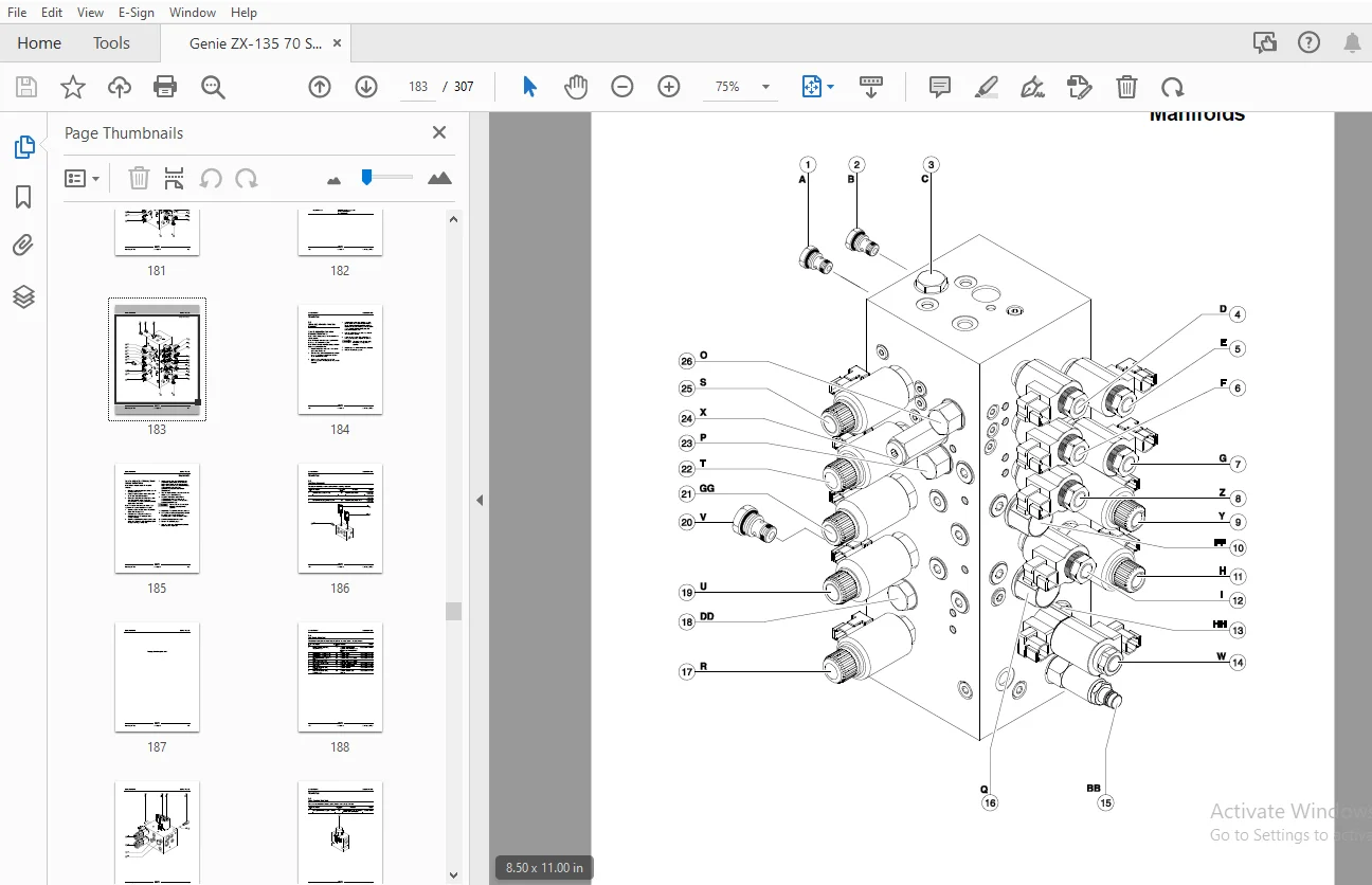
Front Cover...........................................................................................  1
Introduction Introduction.............................................................................  2
	Important Information.............................................................................  2
	Find a Manual for this Model......................................................................  2
	Revision History..................................................................................  3
	Serial Number Legend..............................................................................  5
Section 1 Safety Rules................................................................................  6
	General Safety Rules..............................................................................  6
Section 2 Specifications.............................................................................. 17
	Machine Specifications............................................................................ 17
	Performance Specifications........................................................................ 17
	Hydraulic Specification........................................................................... 18
	Hydraulic Component Specifications................................................................ 20
	Deutz TD2011L04i Engine Specifications............................................................ 22
	Deutz TD 2.9 Engine Specifications................................................................ 23
	Perkins 1104D-44T Engine Specifications........................................................... 24
	Perkins 854F-34T Engine Specifications............................................................ 26
	Machine Torque Specifications..................................................................... 27
	Hydraulic Hose and Fitting Torque Specifications.................................................. 28
	Torque Procedure.................................................................................. 29
	SAE and Metric Fasteners Torque Charts............................................................ 30
Section 3 Scheduled Maintenance Procedures............................................................ 31
	Introduction...................................................................................... 31
	Pre-Delivery Preparation Report................................................................... 35
	Maintenance Inspection Report..................................................................... 37
	Checklist A Procedures............................................................................ 39
		A-1 Inspect the Manuals and Decals............................................................ 39
		A-2 Perform Pre-operation Inspection.......................................................... 40
		A-3 Perform Function Tests.................................................................... 40
		A-4 Perform Engine Maintenance – Perkins Models............................................... 41
		A-5 Perform Engine Maintenance – Deutz Models................................................. 41
		A-6 Check the Hydraulic Return Filter Condition Indicator..................................... 42
		A-7 Perform 30-Day Service.................................................................... 43
		A-8 Grease the Turntable Rotation Bearing and Rotate Gear..................................... 43
		A-9 Replace the Drive Hub Oil................................................................. 44
	Checklist B Procedures............................................................................ 45
		B-1 Inspect the Batteries..................................................................... 45
		B-2 Inspect the Electrical Wiring............................................................. 46
		B-3 Test the Key Switches..................................................................... 48
		B-4 Inspect the Engine Air Filter............................................................. 50
		B-5 Check the Oil Cooler and Cooling Fins - Deutz Models...................................... 51
		B-6 Check the Exhaust System.................................................................. 52
		B-7 Confirm the Proper Brake Configuration.................................................... 53
		B-8 Inspect the Tires, Wheels and Lug Nut Torque.............................................. 54
		B-9 Check the Drive Hub Oil Level and Fastener Torque......................................... 54
		B-10 Test the Platform Self-leveling.......................................................... 55
		B-11 Test the Engine Idle Select Operation.................................................... 56
		B-12 Test the Ground Control Override......................................................... 57
		B-13 Test the Drive Brakes.................................................................... 58
		B-14 Test the Drive Speed – Stowed Position................................................... 58
		B-15 Test the Drive Speed – Raised or Extended................................................ 59
		B-16 Test the Drive Speed – Raised and Extended............................................... 60
		B-17 Test the Alarm and Optional Flashing Beacon.............................................. 60
		B-18 Perform Hydraulic Oil Analysis........................................................... 61
		B-19 Test the Turntable Level Sensor.......................................................... 61
		B-20 Test the Secondary Boom Angle Sensor..................................................... 63
		B-21 Test the Primary Boom Angle Sensor....................................................... 65
		B-22 Test the Safety Envelope Limit Switches.................................................. 67
		B-23 Test the Recovery Mode System............................................................ 71
		B-24 Inspect the Calibration Decal............................................................ 72
		B-25 Inspect for Turntable Bearing Wear....................................................... 73
	Checklist C Procedures............................................................................ 74
		C-1 Perform Engine Maintenance - Deutz Models................................................. 74
		C-2 Perform Engine Maintenance - Deutz Models................................................. 74
		C-3 Perform Engine Maintenance - Perkins Models............................................... 75
		C-4 Replace the Engine Air Filter Element..................................................... 75
		C-5 Grease the Platform Overload Mechanism (if equipped)...................................... 76
		C-6 Test the Platform Overload System (if equipped)........................................... 77
		C-7 Check and Adjust the Engine RPM........................................................... 79
		C-8 Inspect for Turntable Bearing Wear........................................................ 82
	Checklist D Procedures............................................................................ 84
		D-1 Check the Boom Wear Pads.................................................................. 84
		D-2 Check the Free-wheel Configuration........................................................ 85
		D-3 Replace the Drive Hub Oil................................................................. 86
		D-4 Adjust the Turntable Rotatation Gear Backlash............................................. 88
		D-5 Replace the Hydraulic Filter Elements..................................................... 89
		D-6 Perform Engine Maintenance - Deutz Models................................................. 90
		D-7 Perform Engine Maintenance - Perkins Models............................................... 91
		D-8 Check the Turntable Rotation Bearing Bolts................................................ 91
	Checklist E Procedures............................................................................ 93
		E-1 Test or Replace the Hydraulic Oil......................................................... 93
		E-2 Perform Engine Maintenance - Perkins Models............................................... 95
		E-3 Perform Engine Maintenance - Deutz Models................................................. 95
		E-4 Perform Engine Maintenance - Perkins Models............................................... 96
		E-5 Perform Engine Maintenance - Perkins Models............................................... 96
		E-6 Perform Engine Maintenance - Deutz Models................................................. 97
		E-7 Perform Engine Maintenance - Perkins Models............................................... 97
		E-8 Perform Engine Maintenance - Deutz Models................................................. 98
Section 4 Repair Procedures........................................................................... 99
	Introduction...................................................................................... 99
	Platform Controls.................................................................................101
		Platform Controls.............................................................................101
		1-1 Platform Circuit Board....................................................................101
			How to Remove the LED Circuit Board.......................................................103
		1-2 Joysticks - How to Calibrate a Joystick...................................................103
			How to Reset a Proportional Valve Coil Default............................................107
			How to Set the Function Thresholds and Default Functions Speeds...........................108
			How to Adjust the Function Speeds.........................................................110
			How to Adjust the Function Ramp Rate Setting..............................................110
	Platform Components...............................................................................111
		2-1 Platform..................................................................................111
		2-2 Platform Leveling Cylinder................................................................112
		2-3 Platform Rotator..........................................................................113
			How to Bleed the Platform Rotator.........................................................114
		2-4 Platform Level Sensor - How to Calibrate the Platform Level Sensor........................115
		2-5 Platform Overload System (if equipped)....................................................116
		2-6 Platform Overload Recovery Message........................................................117
	Jib Boom Components...............................................................................119
		3-1 Jib Boom Cable Track......................................................................120
			How to Repair the Cable Track.............................................................121
		3-2 Jib Boom..................................................................................122
		3-3 Jib Boom Lift Cylinder....................................................................124
		3-4 Jib Boom Level Cylinder...................................................................125
		3-5 Jib Boom Extension Cylinder...............................................................126
		3-6 Jib Boom Bellcrank Angle Sensor - How to Calibrate the Jib Boom Bellcrank Angle Sensor....127
	Boom Components...................................................................................133
		4-1 Primary Boom Cable Track..................................................................134
			How to Repair the Primary Boom Cable Track................................................136
		4-2 Secondary Boom Cable Track................................................................136
			How to Repair the Secondary Boom Cable Track..............................................138
		4-3 Primary Boom..............................................................................139
		4-4 Primary Boom Lift Cylinder................................................................141
		4-5 Secondary Boom Lift Cylinder..............................................................142
		4-6 Primary Boom Extension Cylinder...........................................................145
		4-7 Secondary Boom Extension Cylinders........................................................146
		4-8 Primary Boom Angle Sensor - How to Calibrate the Primary Boom Angle Sensor................147
		4-9 Secondary Boom Angle Sensor - How to Calibrate the Secondary Boom Angle Sensor............152
	Engines...........................................................................................157
		5-1 RPM Adjustment............................................................................157
		5-2 Flex Plate................................................................................157
			How to Install the Flex Plate.............................................................158
	Ground Controls...................................................................................159
		6-1 Bypass/Recovery Key Switch................................................................159
			How to Use the Recovery Mode..............................................................161
		6-2 Circuit Boards............................................................................162
		6-3 Membrane Decal............................................................................164
		6-4 Full Machine Calibration..................................................................165
	Display Module....................................................................................166
	Hydraulic Pumps...................................................................................175
		7-1 Function Pump.............................................................................175
			How to Prime the Function Pump............................................................176
			How to Adjust the Function Pump Standby Pressure..........................................176
			How to Adjust the Function Pump Pressure Compensator......................................176
		7-2 Drive Pump................................................................................178
			How to Prime the Drive Pump...............................................................179
	Manifolds.........................................................................................180
		8-1 Function Manifold Components..............................................................180
		8-2 Valve Adjustments - Function Manifold.....................................................184
		8-3 Platform Manifold.........................................................................186
		8-4 Jib Boom Manifold.........................................................................188
		8-5 Flow Control Mainfold.....................................................................190
		8-6 Function Enable Valve.....................................................................191
		8-7 Turntable Rotation Manifold...............................................................192
		8-8 Steer and Axle Manifold...................................................................193
		8-9 Valve Adjustments - Steer and Axle Manifold...............................................197
		8-10 Traction Manifold Components.............................................................198
		8-11 Valve Adjustments - Traction Manifold....................................................202
		8-12 Drive Oil Diverter Manifold Components (welder option)...................................203
		8-13 Valve Coils..............................................................................204
			How to Test a Coil Diode..................................................................205
	Turntable Rotation Components.....................................................................206
		9-1 Turntable Rotation Assembly...............................................................206
			How to Adjust the Turntable Rotation Gear Backlash........................................207
		9-2 Turntable Level Sensor - How to Calibrate the Turntable Level Sensor......................208
	Axle Components...................................................................................211
		10-1 Steer Sensors............................................................................211
			How to Calibrate a Replacement Steer Sensor...............................................213
			How to Calibrate All Steer Sensors........................................................213
		10-2 Steer Cylinders..........................................................................215
		10-3 Axle Extension Cylinders.................................................................216
		10-4 Axle Angle Sensors - How to Calibrate the Axle Angle Sensors.............................217
Section 5 Fault Codes.................................................................................219
	Introduction......................................................................................219
	Control System Fault Codes........................................................................220
	Fault Matrix......................................................................................237
	Deutz TD 2.9 L4 Engine Fault Codes................................................................238
	Perkins 854F-34T Engine Fault Code................................................................253
Section 6 Schematics..................................................................................261
	Introduction......................................................................................261
	Wire Circuit Legend...............................................................................262
	Wire Color Legend.................................................................................266
	Limit Switches and Angle Sensors..................................................................271
	Circuit Connector Legend..........................................................................275
	Drive Chassis and Platform Controller Pin Legend..................................................278
	Safety Controller Pin Legend......................................................................279
	Turntable Controller Pin Legend...................................................................280
	Telematics Connector Pin Legend...................................................................281
	Engine Relay and Fuse Panel Legend - Deutz TD2011L04i.............................................282
	Engine Relay and Fuse Panel Legend- Deutz TD2.9 Models............................................283
	Engine Relay and Fuse Panel Legend - Perkins 1104D-44T............................................284
	Engine Relay and Fuse Panel Legend- Perkins 854F Models...........................................285
	Electrical Symbols Legend.........................................................................286
	Hydraulic Symbols Legend..........................................................................287
	Perkins 1104D Engine Electrical Schematic.........................................................290
	Perkins 854F-34T Engine Electrical Schematic......................................................292
	Perkins 854F-34T Engine Harness...................................................................293
	Deutz TD2.9 Engine Electrical Schematic...........................................................296
	Deutz TD2.9 Engine Harness........................................................................297
	Generator Wiring Schematic........................................................................299
	Hydraulic Generator (Welder Option)...............................................................302
	Hydraulic Schematic...............................................................................303
	Electrical Schematic (Includes Deutz Engine)......................................................306
Back Cover............................................................................................307
S.S 05/24