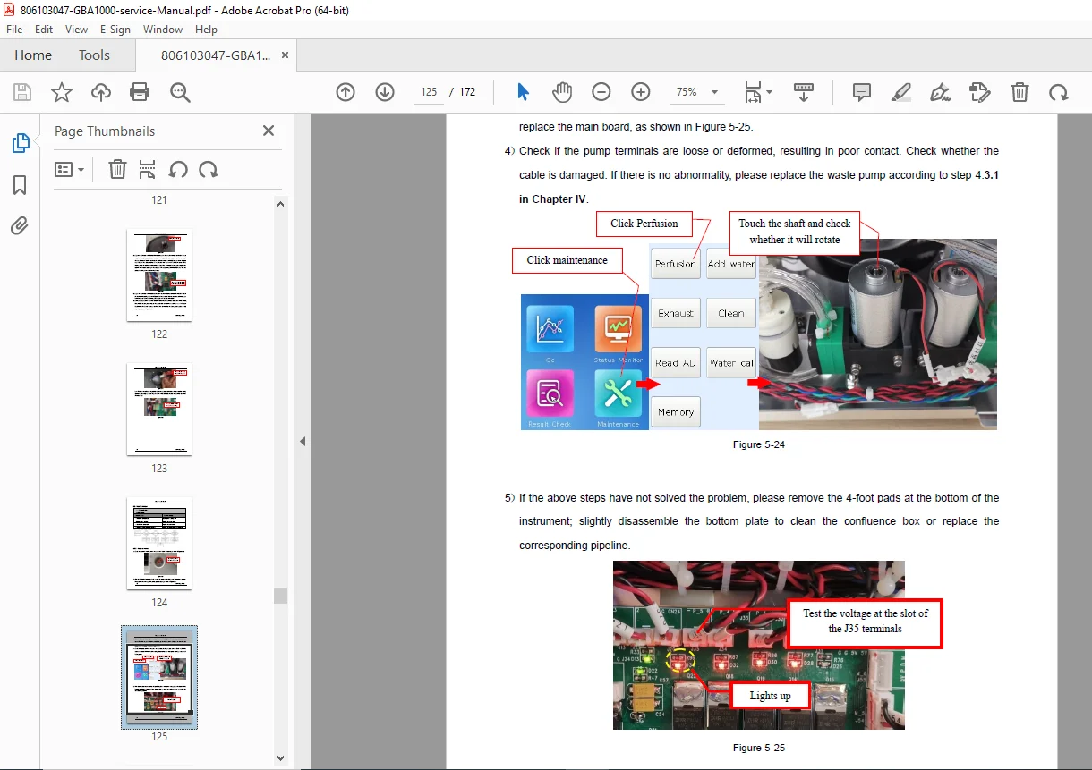
Goldsite GBA-1000 Clinical Chemistry Analyzer Service Manual PDF GBASM01
Original price was: $95.00.$30.95Current price is: $30.95.
Official factory service manual for the Goldsite GBA-1000 Clinical Chemistry Analyzer (Version GBASM01). Covers full system installation, analyser spectrophotometry principles, all 12 mechanical and optical components with calibration procedures, step-by-step replacement of 18 FRU modules including optical unit, plunger pump, reaction disk, halogen lamp, and screen. Includes 25 complete fault troubleshooting workflows and full error code reference. Essential for biomedical engineers. Instant PDF — 172 pages.
Description
Goldsite GBA-1000 Clinical Chemistry Analyzer Service Manual GBASM01 PDF DOWNLOAD
DESCRIPTION
Goldsite GBA-1000 Clinical Chemistry Analyzer — Official Factory Service Manual (PDF Download)
This is the official Goldsite Diagnostics factory service manual for the GBA-1000 Clinical Chemistry Analyzer, Version GBASM01. At 172 pages, this is the authoritative technical reference for biomedical engineers, clinical laboratory technicians, and authorized Goldsite service personnel responsible for the installation, commissioning, calibration, preventive maintenance, component replacement, and fault repair of the GBA-1000 automated chemistry analyzer.
The GBA-1000 operates on the principle of spectrophotometry using the Lambert-Beer law for quantitative absorption analysis, measuring analyte concentrations across a broad clinical chemistry test menu using a rotating reaction disk, cooled reagent carousel, halogen light source, and precision optical module. This manual covers every service-critical system from the initial site survey through full subsystem disassembly and reassembly, with detailed fault flowcharts and repair procedures for all 25 known fault conditions.
📋 File Details
| Field | Details |
|---|---|
| Manual Version | GBASM01 |
| Model | GBA-1000 Clinical Chemistry Analyzer |
| Manufacturer | Goldsite Diagnostics Inc. |
| Equipment Category | In-Vitro Diagnostic (IVD) — Clinical Chemistry Analyzer |
| Measurement Principle | Spectrophotometry (Lambert-Beer Law) |
| PDF Quality | High-quality digital text — fully readable |
| Number of Pages | 172 pages |
| File Format | |
| Language | English |
Table of Contents
CHAPTER I — SYSTEM INSTALLATION
- 1.1 Environmental Requirements — Indoor use only, dust-free and corrosion-free environment, bench specifications (min. 1 × 0.7m, flat to 1/200 inclination, min. 50kg load capacity), max altitude 2000m, EMI separation from centrifuges and high-power equipment
- 1.2 Power Requirements — AC 220V ±22V, 50 ±1Hz, three-core grounded cord (fuse: F5L250V), UPS ≥1500W recommended, neutral-to-ground voltage requirement, socket within 1m
- 1.3 Temperature and Humidity Requirements — Working temperature 10°C–30°C, relative humidity 30%–70% non-condensing, air conditioning guidance
- 1.4 Water Supply and Drainage Requirements — Inlet/outlet plumbing specifications and connections
- 1.5 Installation Process — 19-step site commissioning procedure: inlet conduit connection, waste tank drain setup, power-on sequence, account login, Perfusion and Exhaust operations (minimum 3×), 30-minute light source stabilization, initial calibration and QC per Operation Manual
CHAPTER II — ANALYSER OVERVIEW
- 2.1 Analyser Test Principle — Spectrophotometry based on Lambert-Beer Law (A=Kbc); molar attenuation coefficient, absorption spectrum analysis, standard curve method for concentration quantification, multi-wavelength absorbance measurement
- 2.2 Analyser Overview — Annotated front-view diagram identifying: Touch screen (operator input/display), Reagent disk (cooled reagent storage carousel), Reaction disk control button (cuvette rotation/replacement), Sample holder (multi-format container support), Thermal printer (results/QC output), On/Off button (power and logout control); rear-view component identification
CHAPTER III — COMPONENTS AND FUNCTIONS
3.1 Components (12 Modules)
- 3.1.1 Reaction Disk Drive Shaft Assembly — Stepper motor drive, shaft coupling, position feedback
- 3.1.2 Reaction Plate — Cuvette array, heating element, temperature control for 37°C incubation
- 3.1.3 Optical Module — Multi-wavelength photometric detection system, photodiode array, wavelength filters
- 3.1.4 Reagent Disk Cooling Module — Refrigeration circuit, temperature stabilization for reagent integrity
- 3.1.5 Probe Outer Washing Module — External probe rinse station, wash well assembly
- 3.1.6 Pump — Rotary pump assembly for reagent aspiration and liquid handling
- 3.1.7 Touch Screen — LCD with resistive/capacitive touch, operator interface board
- 3.1.8 Front Cover — Access panel, safety interlock switch
- 3.1.9 Sample Tray Holder — Multi-format support: standard tubes, micro cups, BCT blood collection tubes
- 3.1.10 YZ Axis Movement Module — Two-axis stepper drive for sample probe positioning (Y: lateral, Z: vertical)
- 3.1.11 Driver Protect Shell — Motor driver board enclosure and heat management
- 3.1.12 Plunger Pump Module — Precision metered dispensing for sample and reagent volumes
3.2 Program Content — 27 Calibration and Detection Procedures
- 3.2.1 Instrument power-on self-test
- 3.2.2 Mainboard power supply voltage test
- 3.2.3 Reaction disk position calibration
- 3.2.4 Sample probe-washing well position calibration
- 3.2.5 Sample probe-reaction cuvette position calibration
- 3.2.6 Sample probe-reagent disk position calibration
- 3.2.7 Sample probe-standard cup position calibration
- 3.2.8 Sample probe-Micro cup position calibration
- 3.2.9 Sample probe-BCT (Blood Collection Tube) position calibration
- 3.2.10 Sample probe-Bubble remove position calibration
- 3.2.11 Light position adjustment
- 3.2.12 Stirring calibration
- 3.2.13 Sample tube detection calibration
- 3.2.14 Reagent disk cover detection
- 3.2.15 Sample probe anti-collision function detection
- 3.2.16 Reaction disk control button function detection
- 3.2.17 Inlet and outlet components detection
- 3.2.18 Serial port detection
- 3.2.19 USB port detection
- 3.2.20 Net port (LAN/LIS) detection
- 3.2.21 Cooling fans 1 and 2 detection on refrigeration components
- 3.2.22 Halogen lamp fan detection
- 3.2.23 Pump valve detection (inner pump, solenoid valve, outer pump, waste pump)
- 3.2.24 Probe inner waterflow detection
- 3.2.25 Printer detection
- 3.2.26 Time test
- 3.2.27 S/N number input
CHAPTER IV — REPLACEMENT OF COMMON PARTS
- 4.1 Disassembly Precautions — ESD protection, biohazard decontamination protocol, pipeline disconnection safety, screw torque guidance
- 4.2 Instrument Pipeline Installation Requirements — Tubing routing standards, connector types and orientation, clockwise tightening sequence
- 4.3 Replace Modules — 18 Field Replacement Procedures
- 4.3.1 Pump unit replacement
- 4.3.2 Washing well unit replacement
- 4.3.3 Optical unit replacement
- 4.3.4 Halogen lamp replacement
- 4.3.5 Reaction disk original (origin) sensor replacement
- 4.3.6 Plunger pump replacement
- 4.3.7 Thermal Printer Control Board replacement
- 4.3.8 Printer head replacement
- 4.3.9 Indicator light control board replacement
- 4.3.10 Sensor board replacement
- 4.3.11 Reaction disk replacement
- 4.3.12 Hall Sensor Board replacement
- 4.3.13 Reaction disk motor module replacement
- 4.3.14 Reagent disk refrigeration module replacement
- 4.3.15 Stirring module replacement
- 4.3.16 QR code scanner replacement
- 4.3.17 Sample probe replacement
- 4.3.18 Screen module replacement
CHAPTER V — TROUBLESHOOTING — 25 Fault Scenarios
Each fault includes a structured Maintenance Process (diagnostic flowchart) and detailed Repair Procedure:
- 5.1 Z-axis Reset Failure
- 5.2 Y-axis Reset Failure
- 5.3 X-axis Reset Failure
- 5.4 Plunger Pump Reset Failure
- 5.5 Reaction Disk Reset Failure
- 5.6 Cooling System Failure
- 5.7 Reaction Disk Heating Failure
- 5.8 Waste Overflow
- 5.9 Rotary Pump with No Water Supply
- 5.10 Sample Tray Holder Overflow
- 5.11 Sample Probe Not Stirring
- 5.12 Unable to Power On Normally
- 5.13 Sample Probe Crash
- 5.14 Liquid Level Detection Abnormality
- 5.15 Reaction Disk Not Responding When Disk Control Button Pressed
- 5.16 No Liquid Dispensing from the Sample Probe
- 5.17 Touch Screen Abnormality
- 5.18 USB Flash Drive Unrecognized
- 5.19 Unable to Connect to LIS
- 5.20 Printer Abnormality
- 5.21 Communication Timeout
- 5.22 Indicating Light Failure
- 5.23 Insufficient Clean Water
- 5.24 Waste Water is Full
- 5.25 Self-Test Abnormal
CHAPTER VI — ERROR CODE AND EXPLANATION
Complete error code reference table with fault descriptions and recommended corrective actions for all GBA-1000 system-generated error codes.
✅ Who Needs This Manual?
- Biomedical engineers performing installation commissioning and periodic preventive maintenance on the Goldsite GBA-1000
- Clinical laboratory technicians responding to instrument alarms, error codes, or reagent/probe related faults
- Hospital biomedical departments and clinical lab managers maintaining GBA-1000 instruments in-house
- Independent biomedical service companies servicing Goldsite chemistry analyzers without OEM call-out costs
- Service engineers needing the complete 27-point calibration sequence post module replacement or relocation
🔬 Restore Your GBA-1000 to Full Calibration — Get the Factory Manual Now
With 172 pages of official Goldsite Diagnostics service documentation — covering all 12 mechanical and optical modules, 18 illustrated step-by-step FRU replacement procedures, 27 factory calibration workflows, and complete troubleshooting for all 25 fault conditions with error code explanations — this is the definitive workshop reference for the GBA-1000 clinical chemistry analyzer. Purchase now for an instant PDF download.