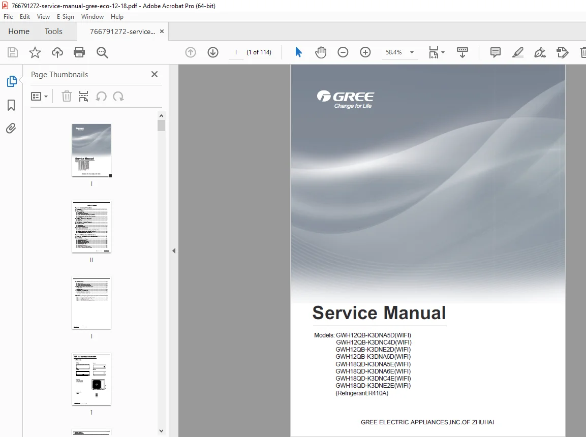
Gree ECO 12/18 Split Air Conditioner Service Repair Manual WiFi R410A PDF
Original price was: $95.00.$18.95Current price is: $18.95.
Official factory service manual for Gree ECO series wall-mounted split air conditioners covering 12,000 and 18,000 BTU models with WiFi connectivity. Comprehensive technical documentation includes installation procedures, electrical wiring diagrams, refrigerant system schematics, PCB layouts, error code diagnostics, troubleshooting flowcharts, and complete parts lists. Essential guide for HVAC technicians servicing R410A refrigerant systems with detailed specifications and repair procedures.
Description
Gree ECO 12/18 Split Air Conditioner Service Repair Manual WiFi R410A PDF DOWNLOAD
DESCRIPTION
This is the complete official Gree ECO Series Service Manual for wall-mounted split air conditioner systems covering both 12,000 BTU (GWH12QB) and 18,000 BTU (GWH18QD) capacity models with integrated WiFi control functionality and R410A refrigerant.
Models Covered by This Service Manual
12,000 BTU Models (GWH12QB Series):
- GWH12QB-K3DNA6D (WiFi) – Product Code: CB427004702/CB427004703
- GWH12QB-K3DNA5D (WiFi) – Product Code: CB425007001
- GWH12QB-K3DNC4D (WiFi) – Product Code: CB444001502
- GWH12QB-K3DNE2D (WiFi) – Product Code: CB462000201
18,000 BTU Models (GWH18QD Series):
- GWH18QD-K3DNA6E (WiFi) – Product Code: CB427006400/CB427006401
- GWH18QD-K3DNA5E (WiFi) – Product Code: CB425007100
- GWH18QD-K3DNC4E (WiFi) – Product Code: CB444002900
- GWH18QD-K3DNE2E (WiFi) – Product Code: CB462000300
All models use R410A refrigerant and feature WiFi smart control via smartphone/tablet applications.
Complete Manual Contents
This Gree air conditioner service manual PDF is divided into two comprehensive parts covering all service aspects:
PART I: TECHNICAL INFORMATION
1. Summary & Model Overview
- Indoor unit panel configurations (A5, A6, C2, E2 panels)
- Outdoor unit specifications
- Remote controller (YAN1F1) introduction
- Model identification and serial number locations
2. Detailed Specifications
- Complete specification sheets for all models
- Cooling capacity ranges: 12K BTU (3,200W min/3,400W max) and 18K BTU (4,600W min/5,000W max)
- Heating capacity data: 12K BTU (3,400W) and 18K BTU (5,000W)
- Power consumption specifications
- Electrical ratings (220-240V, 50Hz, single phase)
- Energy efficiency ratios (EER: 3.21, COP: 3.61, SEER: 6.1)
- Operation characteristic curves
- Capacity variation according to temperature
- Cooling and heating data at rated frequency
- Noise level specifications and curves
- Application area guidelines (15-22m² for 12K, 21-31m² for 18K)
3. Dimensional Diagrams
- Indoor unit outline dimensions (790x275x200mm for 12K, 970x300x224mm for 18K)
- Outdoor unit dimensional specifications
- Installation clearance requirements
- Mounting bracket specifications
4. Refrigerant System Diagrams
- Complete R410A refrigerant circuit schematics
- Component location diagrams
- Pressure/temperature relationship charts
- Refrigerant charge specifications
- System flow diagrams for cooling and heating modes
5. Electrical Components & Wiring
- Comprehensive wiring diagrams for indoor and outdoor units
- PCB (Printed Circuit Board) layouts with component identification
- Power supply connection diagrams
- Control circuit schematics
- Sensor wiring configurations
- WiFi module electrical connections
- Terminal block connection specifications
- Color-coded wire identification
6. Function & Control Systems
- Remote controller complete operation guide
- WiFi smart control setup for smartphones and tablets
- Gree+ app installation and configuration
- Mode descriptions: Auto, Cool, Dry, Fan, Heat
- Advanced features: Sleep mode, Timer, Turbo, Energy-saving
- Temperature control parameters
- Fan speed control (5 speeds: Super High/High/Medium/Low/Super Low)
- Swing function operation
- Self-diagnosis display codes
- Protection function details
PART II: INSTALLATION AND MAINTENANCE
7. Installation & Maintenance Safety Notes
- Carbon monoxide safety warnings
- Gasoline and flammable materials handling
- Hot component precautions
- Coolant (ethylene glycol) safety information
- Nitrogen pressure warnings for shock absorbers
- Electrical safety requirements
- Proper tool usage guidelines
8. Complete Installation Procedures
8.1 Installation Dimension Diagrams
- Wall mounting bracket positioning
- Pipe routing dimensions
- Clearance requirements
- Drain hose specifications
8.2 Installation Parts Checking
- Component verification checklist
- Accessory inventory
- Hardware identification
8.3 Location Selection Guidelines
- Indoor unit placement recommendations
- Outdoor unit positioning requirements
- Airflow consideration
- Service access requirements
- Structural load-bearing verification
8.4 Electrical Connection Requirements
- Power supply specifications (220-240V AC, 50Hz)
- Wire gauge recommendations
- Grounding requirements
- Circuit breaker sizing
- All-pole disconnect switch installation (3mm minimum contact separation)
8.5 Indoor Unit Installation
- Wall mounting bracket installation procedures
- Leveling and alignment specifications
- Pipe hole preparation and drilling
- Indoor unit hanging procedures
- Panel and cover installation
- Power cord routing and connection
- Color-coded wiring terminal connections
- Wire clip installation
- Final inspection checklist
8.6 Outdoor Unit Installation
- Support bracket installation and anchoring
- Expansion screw specifications (6-10 screws depending on capacity)
- Outdoor unit positioning (minimum 3cm above floor)
- Drain joint installation (cooling/heating models)
- Foot hole mounting and securing
- Pipe connection procedures with torque specifications:
- Φ6mm: 15-20 N·m
- Φ9.52mm: 30-40 N·m
- Φ12mm: 45-55 N·m
- Φ16mm: 60-65 N·m
- Φ19mm: 70-75 N·m
- Electrical wire connection
- Pipe routing and protection
8.7 Vacuum Pumping & Leak Detection
- Vacuum pump connection procedures
- Proper evacuation techniques (10-15 minutes at -0.1MPa)
- Pressure holding test (1-2 minutes)
- Leak detection methods using detector or soap water
- Valve opening procedures using hex wrench
- System integrity verification
8.8 Post-Installation Checks & Test Operation
- 11-point installation verification checklist
- Firm mounting confirmation
- Refrigerant leak testing
- Heat insulation inspection
- Drainage verification
- Power supply voltage verification
- Electrical wiring correctness
- Grounding security check
- Power cord specification compliance
- Airflow obstruction clearance
- Valve opening verification
- Test operation procedures for all modes
- Performance verification
9. Comprehensive Maintenance Section
9.1 Complete Error Code List This inverter AC error code manual includes detailed diagnostics:
- E1 – High Pressure Protection: Causes include excessive refrigerant, poor heat exchange, dirty heat exchanger, high ambient temperature, pressure switch malfunction
- E2 – Freeze Protection: Indoor fan rotation issues, evaporator contamination, airflow restrictions
- E4 – High Discharge Temperature: Overheating prevention, compressor protection
- E5 – Overcurrent Protection: Power voltage instability, overload conditions
- E6 – Communication Malfunction: Indoor/outdoor unit communication failure
- E8 – Overload Protection: System overload conditions
- F1 – Indoor Ambient Temperature Sensor: Open/short circuit diagnostics
- F2 – Indoor Evaporator Temperature Sensor: Sensor failure diagnostics
Each error code includes:
- Indicator light display patterns
- Air conditioner operational status during fault
- Possible root causes
- Step-by-step countermeasures and solutions
9.2 Main Malfunction Troubleshooting
- Detailed flowcharts for systematic diagnosis
- Component-level troubleshooting procedures
- Voltage and resistance testing specifications
- Sensor resistance tables for temperature verification
- Protection function diagnostics:
- Compressor overload protection sequences
- Discharge temperature protection levels
- Module overheating protection
- Voltage sag protection
- Overcurrent protection thresholds
- Communication fault diagnosis
9.3 Normal Malfunction Troubleshooting
- Common operational issues resolution
- Performance optimization procedures
- Customer complaint diagnostics
- Seasonal operation considerations
10. Exploded View Diagrams & Parts Lists
10.1 Indoor Unit Parts Breakdown
- Complete component identification
- Part number reference
- Assembly sequence illustrations
- Fastener specifications
10.2 Outdoor Unit Parts Breakdown
- Detailed component layout
- Refrigerant system components
- Electrical component identification
- Fan and motor assemblies
- Compressor specifications
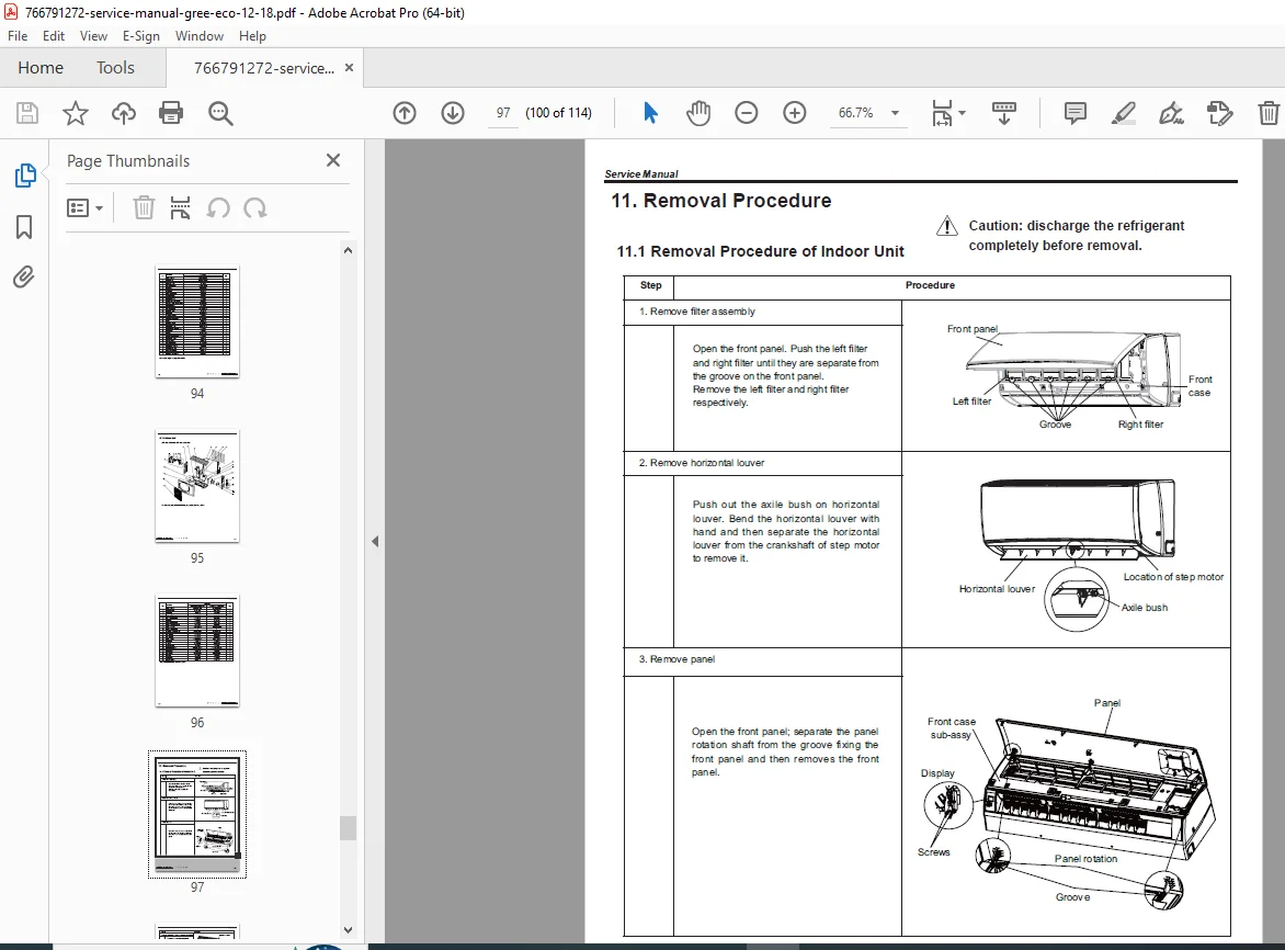
11. Component Removal Procedures
11.1 Indoor Unit Disassembly
- Front panel removal
- Air filter access
- Evaporator coil removal
- Fan motor extraction
- Control board removal
- Temperature sensor replacement
- Drain pan service
- Step-by-step photo-illustrated procedures
11.2 Outdoor Unit Disassembly
- Cabinet panel removal
- Condenser coil access
- Compressor removal procedures
- Fan motor replacement
- PCB removal and replacement
- Refrigerant recovery requirements
- Proper handling of pressurized components
Technical Appendices
Appendix 1: Temperature Conversion Reference
- Celsius to Fahrenheit conversion chart
- Quick reference table for common HVAC temperatures
Appendix 2: Connection Pipe Configuration
- Refrigerant line sizing charts
- Pipe length limitations
- Elevation restrictions
- Additional refrigerant charge calculations
Appendix 3: Pipe Expanding (Flaring) Method
- Proper flaring tool usage
- Flare dimension specifications
- Quality inspection criteria
- Common flaring mistakes to avoid
Appendix 4: Temperature Sensor Resistance Table
- Complete resistance-to-temperature correlation
- Sensor testing procedures
- Normal operating ranges
- Fault diagnosis using resistance values
Key Technical Specifications Summary
12,000 BTU Models (GWH12QB):
- Cooling Capacity: 3,200W (Min) / 3,400W (Max)
- Heating Capacity: 3,400W
- Power Input Cooling: 997W (Min) / 942W (Max)
- Power Input Heating: 942W
- Current Draw: 4.50A (Cooling) / 4.4A (Heating)
- Air Flow: 560/480/410/290 m³/h (5-speed fan)
- Dehumidifying Capacity: 1.4 L/h
- Indoor Unit Dimensions: 790×275×200 mm
- Indoor Unit Weight: 9 kg
- Evaporator: Aluminum fin-copper tube, Φ5mm, 584×22.8×266.7mm
- Fan Type: Cross-flow Φ98×580mm
- Sound Pressure: 28-42 dB(A)
18,000 BTU Models (GWH18QD):
- Cooling Capacity: 4,600W
- Heating Capacity: 5,000W
- Power Input Cooling: 1,430W
- Power Input Heating: 1,380W
- Current Draw: 6.34A (Cooling) / 6.12A (Heating)
- Air Flow: 850/720/610/520 m³/h
- Dehumidifying Capacity: 1.8 L/h
- Indoor Unit Dimensions: 970×300×224 mm
- Indoor Unit Weight: 13.5 kg
- Evaporator: Aluminum fin-copper tube, Φ7mm, 715×25.4×304.8mm
- Fan Type: Cross-flow Φ106×706mm
- Sound Pressure: 33-45 dB(A)
Common Specifications (Both Models):
- Refrigerant Type: R410A
- Voltage: 220-240V AC, 50Hz, Single Phase
- Compressor Type: Rotary inverter compressor
- Frame Design: Double cradle
- Energy Efficiency: EER 3.21, COP 3.61, SEER 6.1
- Operating Temperature Range: Cooling 16-43°C, Heating -15-24°C
- WiFi Control: Built-in module with smartphone app support
Professional Service Features
This split air conditioner wiring diagram manual provides:
- Visual Learning: Large, clear illustrations with numbered callouts
- Multi-Language Support: English technical documentation
- Measurement Standards: Both metric (mm, kg, L) and imperial (in, lbs, gal) units
- Safety Emphasis: Warning symbols and caution notes throughout
- Torque Specifications: Precise tightening values to prevent damage
- Diagnostic Aids: Comprehensive troubleshooting flowcharts
- Parts Integration: Cross-referenced exploded views with part numbers
Who Should Use This Manual?
This Gree WiFi AC installation guide is essential for:
- Licensed HVAC technicians and installers
- Air conditioning repair specialists
- R410A certified refrigeration technicians
- Commercial building maintenance teams
- Technical training institutions
- HVAC service companies
- Property management maintenance staff
Important Technical Notes
- Manual requires basic HVAC knowledge and proper certification for refrigerant handling
- R410A systems operate at higher pressures than R22 – use appropriate tools and gauges
- WiFi module configuration requires smartphone with Gree+ application
- Installation must comply with local electrical and building codes
- Refrigerant work requires EPA Section 608 certification (or local equivalent)
- Use only specified torque values to prevent refrigerant leaks
- Regular filter cleaning improves efficiency and prevents error codes
This is the authentic factory service manual used by authorized Gree service centers worldwide for professional installation, maintenance, and repair of these popular wall-mounted split air conditioning systems.
FILE DETAILS
| Attribute | Details |
|---|---|
| Manual Name | Gree ECO Series Service Manual |
| Models Covered | GWH12QB-K3DNA5D/6D/C4D/E2D (12K BTU) GWH18QD-K3DNA5E/6E/C4E/E2E (18K BTU) |
| Capacity Range | 12,000 BTU and 18,000 BTU |
| Refrigerant Type | R410A |
| Special Features | WiFi Control, Inverter Technology |
| Manual Type | Factory Service & Installation Manual |
| File Format | PDF (Searchable & Printable) |
| File Size | ~28 MB |
| Total Pages | 114 pages |
| PDF Quality | High-resolution professional factory manual |
| Language | English |
| Publisher | Gree Electric Appliances, Inc. of Zhuhai |
| Creation Date | April 2016 (Latest revision) |