Gree GMV5E DC Inverter VRF Multi-Split Air Conditioner Service Manual PDF
Original price was: $85.00.$16.95Current price is: $16.95.
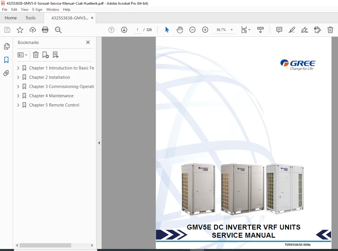
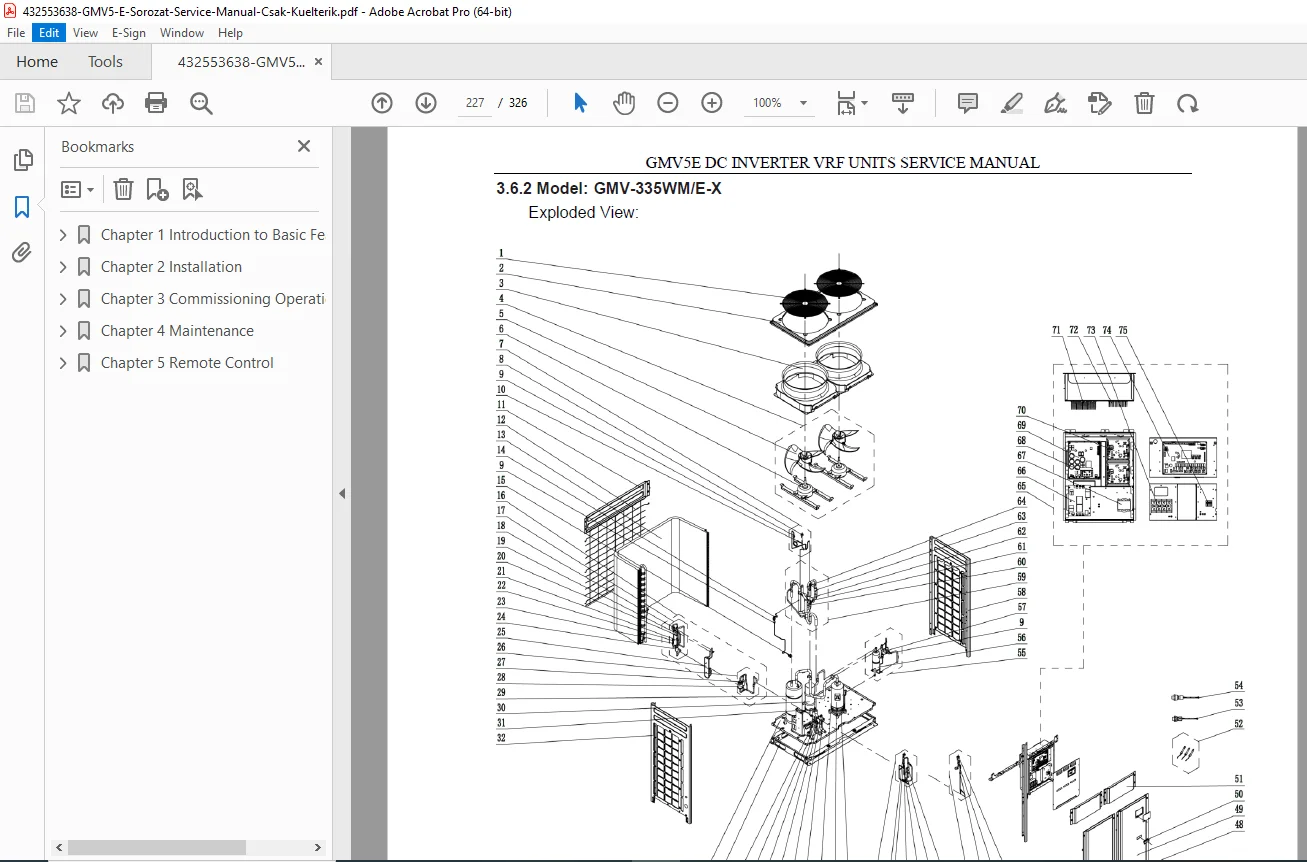
Official Gree GMV5E DC Inverter VRF (Variable Refrigerant Flow) service manual for HVAC technicians. This comprehensive 326-page PDF covers installation, commissioning, maintenance, and troubleshooting for GMV-224WM through GMV-615WM outdoor units (22.4-61.5kW capacity). Includes detailed piping diagrams, electrical parameters, refrigerant charging, compressor replacement, failure codes, remote control setup, and exploded parts views. Uses R410A refrigerant. Essential for commercial HVAC contractors and VRF system technicians.
Description
Gree GMV5E DC Inverter VRF Multi-Split Air Conditioner Service Manual PDF DOWNLOAD
DESCRIPTION
Gree GMV5E DC Inverter VRF Units Service Manual – Complete Professional HVAC System Service Reference
This is the official factory service manual for the Gree GMV5E series DC Inverter Variable Refrigerant Flow (VRF) air conditioning systems. Published in August 2016 by Gree Electric Appliances, this professional-grade technical documentation is essential for qualified HVAC technicians, VRF system specialists, and commercial air conditioning contractors who install, commission, maintain, and repair these advanced multi-split climate control systems.
📋 FILE DETAILS
- Manual Title: Installation, Commissioning, and Maintenance Manual for Export-oriented GMV5 DC Inverter Multi-connected Units
- System Covered: GMV5E DC Inverter VRF Units
- Models Included:
- GMV-224WM/E-X (22.4 kW capacity)
- GMV-280WM/E-X (28.0 kW capacity)
- GMV-335WM/E-X (33.5 kW capacity)
- GMV-400WM/E-X (40.0 kW capacity)
- GMV-450WM/E-X (45.0 kW capacity)
- GMV-504WM/E-X (50.4 kW capacity)
- GMV-560WM/E-X (56.0 kW capacity)
- GMV-615WM/E-X (61.5 kW capacity)
- Manufacturer: Gree Electric Appliances
- Publication Date: August 23, 2016
- Refrigerant: R410A
- Power Supply: 3-phase, 380-415V, 50/60Hz
- Total Pages: 326 pages
- File Format: PDF
- PDF Quality: High-quality official manual with detailed diagrams
- Language: English
- Page Size: A4 format
🔧 COMPREHENSIVE COVERAGE INCLUDES:
Preface
Safe Operation Requirements:
- Engineering and installation specifications
- Commissioning and maintenance procedures
- Basic principles and implementation methods
- Professional operator requirements
- National/local safety requirements compliance
- Technical specifications adherence
- System failure prevention
- Personnel safety accident prevention
Chapter 1: INTRODUCTION TO BASIC FEATURES OF UNITS
1.1 Basic Operating Principle:
VRF System Architecture:
- Multiple outdoor modules in parallel
- Multiple indoor units (IDUs) in parallel connection
- Load-based outdoor module enablement
Cooling Mode Operation:
- Outdoor heat exchanger as condenser
- Indoor heat exchangers as evaporators (parallel)
- Air circulation for temperature/humidity control
Heating Mode Operation:
- Four-way valve switching (energized status)
- Outdoor heat exchanger as evaporator
- Indoor heat exchanger as condenser
- Air circulation for indoor climate control
1.2 Model List:
- Complete model specifications
- Product codes
- Nominal capacity ratings
- Power supply requirements
- Unit appearance diagrams
1.3 Internal Piping Design:
Piping Diagrams for:
- GMV-224WM/E-X, GMV-280WM/E-X, GMV-335WM/E-X
- GMV-400WM/E-X
- GMV-450WM/E-X, GMV-504WM/E-X, GMV-560WM/E-X, GMV-615WM/E-X
Component Names and Functions (38 components):
- Compressor: DC inverter, rotational speed control, capacity adjustment
- Compressor heat tape: Oil temperature maintenance, startup reliability
- Compressor casing-top temperature sensor: Exhaust gas temperature detection
- Exhaust pipe temperature sensor: Compressor control and protection
- High-pressure circuit breaker: Overpressure protection
- Oil extractor: Gas-oil separation, system reliability
- Oil equalizing device: Oil distribution among modules
- Heat tape of oil equalizing device: Oil temperature maintenance
- One-way valve: Pressure balancing, backflow prevention
- High-pressure sensor: Real-time pressure monitoring
- Four-way valve: Cooling/heating mode switching
- Heat exchanger: Outdoor heat exchange
- Fan: Heat exchange enhancement
- Defrosting temperature sensor: Defrost detection
- Electronic expansion valve (heating): Refrigerant adjustment
- One-way valve: Flow direction control
- Subcooler electronic expansion valve: Subcooling control
- Subcooler: Tube subcooling control
- Liquid outlet temperature sensor: Temperature monitoring
- Inlet temperature sensor (gas-liquid separator): Backflow prevention
- Gas outlet temperature sensor (subcooler): Gas temperature detection
- Low-pressure sensor: Extra-low pressure avoidance
- Gas-liquid separator: Phase separation, backflow prevention
- Outlet temperature sensor (gas-liquid separator): Internal status detection
- Oil equalizing valve 1: Inter-module oil equalization
- One-way valve: Oil flow control
- Unloading valve: Blind spot pressure control
- Oil equalizing valve 2: Module oil equalization
- Filter: Impurity prevention
- Capillary tube: Flow regulation, pressure reduction
- Liquid valve: Stop valve (factory closed)
- Air valve: Stop valve (factory closed)
- Low-pressure measurement valve: Pressure detection, refrigerant charging
- Oil balance valve: Stop valve (factory closed)
- Oil check valve: Oil quality inspection
- Unloading valve: Blind spot pressure management
- Air by-pass valve: Pressure regulation
- Pressure-balanced valve: Compressor startup assurance
1.4 Basic Parameters of Unit:
- Capacity specifications
- Physical dimensions
- Operating ranges
- Performance characteristics
1.5 Electrical Parameters:
- Power consumption
- Current ratings
- Voltage specifications
- Control voltage
- Motor specifications
1.6 Optional Accessories:
- Available options
- Compatibility information
- Installation requirements
1.7 Basic Requirement for Pipe Connection:
- Pipe sizing
- Material specifications
- Connection methods
- Brazing requirements
1.8 Precautions on Refrigerant Leakage:
- Safety precautions
- Detection methods
- Leak repair procedures
- Environmental considerations
1.9 Unit Operating Temperature:
- Cooling mode temperature range
- Heating mode temperature range
- Ambient temperature limits
Chapter 2: INSTALLATION (Comprehensive Installation Guide)
1. Engineering Installation Preparation:
1.1 Installation Safety:
- Safety requirements
- Personal protective equipment
- Tool safety
- Work area safety
1.2 Importance of Installation Engineering:
- System performance impact
- Efficiency considerations
- Reliability factors
- Service life implications
1.3 Cooperation Between Different Professions:
- Coordination requirements
- Multi-trade integration
- Communication protocols
1.4 Onsite Review of Design Drawing:
- Drawing verification
- Design compliance
- Site condition assessment
1.5 Construction Organization Process:
- Project planning
- Resource allocation
- Timeline management
2. Material Selection:
2.1 Requirement for Selecting Construction Materials:
- Material standards
- Quality requirements
- Compatibility considerations
2.2 Requirement for Selecting Major Materials:
- Copper piping specifications
- Insulation materials
- Electrical components
- Fasteners and supports
3. Installation Space Requirement:
3.1 Place Selection for Installing ODU:
- Location criteria
- Environmental considerations
- Access requirements
3.2 ODU Dimensions and Installation Hole Size:
- Unit dimensions for all models
- Mounting hole patterns
- Clearance requirements
3.3 Installation Space Requirement for ODU:
- Minimum clearances
- Service access space
- Airflow requirements
4. Requirements on Foundation Installation:
4.1 ODU Foundation:
- Foundation specifications
- Load-bearing requirements
- Leveling requirements
4.2 ODU Fixing:
- Mounting methods
- Anchor specifications
- Seismic considerations
4.3 Vibration Reduction for ODU:
- Isolation pads
- Anti-vibration mounts
- Noise reduction
5. Piping Connection:
5.1 Schematic Diagram of Piping Connection:
- System piping layout
- Connection points
- Valve locations
5.2 Schematic Diagram of Piping Sequence:
- Installation sequence
- Critical connections
- Testing points
5.3 Allowable Pipe Length and Drop Height:
- Maximum pipe length specifications
- Height difference limitations
- Capacity impact considerations
5.4 Connection Pipe Among Outdoor Modules:
- Module interconnection
- Parallel piping
- Oil return considerations
5.5 Fitting Pipe Between Outdoor Unit and First Manifold:
- Main piping specifications
- Branch connections
- Pressure drop considerations
6. Pipe Installation and Insulation:
6.1 Pipe Installation for Cooling System:
- Copper pipe installation
- Brazing procedures
- Leak testing
- Flushing procedures
6.2 Pipe Installation for Condensate Water System:
- Drain line sizing
- Slope requirements
- Trap installation
- Termination methods
6.3 Insulation System:
- Insulation material specifications
- Installation procedures
- Vapor barrier requirements
- UV protection
7. Electric and Controller Installation:
7.1 Precautions:
- Electrical safety
- Grounding requirements
- Power quality
7.2 Installation of Power Cable:
- Cable sizing
- Routing requirements
- Connection procedures
- Circuit protection
7.3 Installation of Communication System:
- Communication wiring
- Protocol specifications
- Network topology
- Termination procedures
8. Vacuumization and Desiccation:
8.1 Air-tightness Test:
- Pressure testing
- Leak detection procedures
- Acceptance criteria
8.2 Vacuumization and Desiccation:
- Vacuum pump specifications
- Target vacuum levels
- Hold test procedures
- Moisture removal verification
9. Refrigerant Perfusion:
9.1 Calculation Method for Perfusing Refrigerant:
- Charge calculation formulas
- Pipe volume considerations
- Height adjustment factors
9.2 Method for Perfusing Refrigerant:
- Charging procedures
- Liquid vs. vapor charging
- Charge verification
Chapter 3: COMMISSIONING OPERATION
1. Security Requirements:
1.1 Precautions for Construction:
- Safety protocols
- Quality control
- Documentation
1.2 Precautions for Use of Refrigerants:
- R410A handling
- Safety equipment
- Environmental compliance
2. Introduction to Unit Functions:
2.1 System Function DIP Switch Settings:
- Configuration switches
- Function selection
- Parameter settings
2.2 System Function Button Operations:
- Control interface
- Operational procedures
- Function access
3. Commissioning Process:
3.1 Necessity of VRF Engineering Commissioning:
- Performance verification
- System optimization
- Problem identification
3.2 Required Files and Tools:
- Documentation requirements
- Test equipment list
- Software tools
3.3 Engineering Commissioning Procedures:
- Pre-startup checklist
- Initial startup sequence
- Functional testing
- Performance verification
- Parameter adjustment
- Documentation completion
3.4 References for Proper Unit Operation Parameters:
- Normal operating ranges
- Pressure specifications
- Temperature specifications
- Current draw specifications
Chapter 4: MAINTENANCE
1. Failure Code Table:
- Complete error code list
- Code descriptions
- Probable causes
- Corrective actions
2. Exception Analyzing and Troubleshooting:
2.1 Form Analyzing:
- Symptom-based troubleshooting
- Component failure analysis
- System malfunction diagnosis
2.2 Flowchart Analyzing:
- Diagnostic flowcharts
- Systematic troubleshooting
- Decision trees
3. Key Parts Maintenance:
3.1 Cautions on Controller AP1 Replacement:
- Controller removal procedures
- Programming requirements
- Configuration backup
- Installation procedures
3.2 Compressor Replacement and Cautions:
- Compressor removal procedures
- Oil handling
- Brazing procedures
- System cleanup
- Vacuum and charge procedures
- Startup procedures
3.3 Cautions on Compressor Drive Replacement:
- Inverter board removal
- Safety precautions
- Installation procedures
- Parameter setup
3.4 Assembling and Disassembling Key Parts:
- Component removal procedures
- Service access methods
- Reassembly procedures
3.5 Common Parameter Lists:
- Operating parameters
- Diagnostic parameters
- Service mode parameters
3.6 Exploded Views and Spare Part List:
- Assembly diagrams
- Part numbers
- Part descriptions
- Quantities
Chapter 5: REMOTE CONTROL
1. Engineering Debugger:
1.1 Overview:
- Debugger purpose
- Capabilities
- System requirements
1.2 System Networking:
- Network configuration
- Communication protocols
- Addressing
1.3 Hardware:
- Debugger specifications
- Connection methods
- Interface descriptions
1.4 Software Setup:
- Software installation
- Configuration procedures
- Driver installation
1.5 Using Debugger:
- Operational procedures
- Parameter monitoring
- Data logging
- Troubleshooting functions
1.6 Software Debug:
- Diagnostic functions
- Error analysis
- System optimization
2. Remote Control:
2.1 Major Functions:
- Remote monitoring capabilities
- Control functions
- Alarm management
2.2 Terms and Definitions:
- System terminology
- Parameter definitions
2.3 Network Topology:
- System architecture
- Communication structure
- Component relationships
2.4 Hardware:
- Remote control hardware
- Gateway specifications
- Network devices
2.5 Software:
- Remote monitoring software
- User interface
- Configuration tools
2.6 Software Debug:
- Remote diagnostics
- System testing
- Performance monitoring
2.7 Remote Monitoring System Debug:
- System commissioning
- Communication verification
- Function testing
2.8 Troubleshooting:
- Common problems
- Network issues
- Communication errors
- Resolution procedures
🎯 GMV5E SERIES SPECIFICATIONS:
VRF Technology: ✅ DC Inverter compressor technology
✅ Variable refrigerant flow control
✅ Multi-module outdoor units
✅ Multiple indoor unit connections
✅ Simultaneous cooling and heating capability
Capacity Range: ✅ 22.4 kW to 61.5 kW (8 models)
✅ Modular design for scalability
✅ Load-based capacity control
Refrigerant: ✅ R410A refrigerant system
✅ Environmental compliance
✅ High efficiency performance
Power Supply: ✅ 3-phase, 380-415V
✅ 50/60 Hz operation
✅ International voltage compatibility
System Features: ✅ Oil equalization among modules
✅ Subcooler for efficiency
✅ Gas-liquid separator
✅ Four-way valve reversing
✅ Electronic expansion valve control
✅ Multiple protection functions
💡 IDEAL FOR:
✅ Commercial HVAC contractors
✅ VRF system specialists
✅ Building automation technicians
✅ HVAC service companies
✅ Facility maintenance engineers
✅ MEP (Mechanical, Electrical, Plumbing) contractors
✅ Building management technical staff
✅ Air conditioning installation companies
✅ Anyone servicing Gree VRF systems
🌟 KEY BENEFITS:
- Massive 326 Pages: Most comprehensive VRF documentation
- Eight Models Covered: Complete GMV5E series (22.4-61.5kW)
- Professional VRF System: Advanced multi-split technology
- Complete Installation Guide: From foundation to commissioning
- Detailed Piping Diagrams: Internal and external piping
- 38 Component Descriptions: Complete system understanding
- Refrigerant Charging: Calculation methods and procedures
- Compressor Replacement: Step-by-step procedures
- Failure Code Table: Complete diagnostic codes
- Remote Control Setup: Engineering debugger and monitoring
- Exploded Views: Parts identification and ordering
📥 DOWNLOAD INFORMATION:
- Instant Download: Immediate access after purchase
- Format: PDF with searchable text
- Compatibility: Works on PC, Mac, tablet, smartphone
- Searchable: Full-text search capability
- Printable: Print entire manual or sections
- High Quality: Clear diagrams and schematics
- Professional: Official Gree documentation
⚠️ IMPORTANT NOTES:
- Professional service manual for qualified HVAC technicians
- R410A refrigerant system requiring EPA certification (USA)
- 3-phase electrical system requiring licensed electrician
- Official Gree Electric Appliances documentation
- VRF system complexity requires proper training
- Safety precautions mandatory
- Proper tools and test equipment essential
🔧 REQUIRED SERVICE EQUIPMENT:
- Refrigerant recovery/charging equipment
- Vacuum pump (for R410A)
- Manifold gauges (R410A)
- Leak detector
- Thermometers
- Digital Multimeter
- Megohmmeter
- Torque wrenches
- Tube cutters and flaring tools
- Brazing equipment
- Engineering debugger (Gree)
- Pressure testing equipment
🌟 WHY CHOOSE THIS MANUAL?
This is authentic Gree Electric Appliances factory documentation for the GMV5E VRF system. Variable Refrigerant Flow systems represent advanced HVAC technology requiring factory-level procedures for installation, commissioning, and service. The manual’s comprehensive 326-page coverage makes it essential for commercial HVAC contractors.
Order now for immediate download access to complete Gree GMV5E VRF system service documentation