Gree U-Match DC Inverter R410A Service Manual – PDF DOWNLOAD
Original price was: $65.00.$15.95Current price is: $15.95.
This is the essential Gree U-Match DC Inverter R410A air conditioner service manual for professional technicians. This comprehensive guide provides detailed troubleshooting flowcharts for error codes, complete electrical wiring diagrams for indoor/outdoor units, and step-by-step installation guides for both Duct Type and Cassette Type models. It is perfect for all advanced repair and maintenance work on the U-Match DC Inverter system. This manual incorporates all necessary product data, nomenclature, and operation instructions to ensure a professional service
Description
Gree U-Match DC Inverter R410A Service Manual Installation & Troubleshooting – PDF DOWNLOAD
DESCRIPTION
This is the official factory-issued Gree U-Match Series DC Inverter Air Conditioner Service Manual – the definitive technical guide for expert HVAC technicians engaged in the repair, installation, and maintenance of U-Match Series DC Inverter Air Conditioners using R410A refrigerant. This comprehensive 148-page manual (circa 2016, T1 designation) provides exhaustive technical details to diagnose, install, and safely service all listed duct and cassette type models, ensuring these advanced inverter-driven HVAC systems operate at peak efficiency and reliability.
Product Overview
Gree U-Match Series DC Inverter Air Conditioners:
The U-Match Series represents Gree’s advanced DC inverter air conditioning platform designed for commercial and residential applications, featuring intelligent capacity modulation, energy-efficient operation, and flexible installation options. These systems utilize R410A refrigerant and incorporate state-of-the-art inverter compressor technology with precise electronic controls for superior comfort, energy savings, and quiet operation in both duct-type and cassette-type configurations.
Key Applications:
- Commercial office buildings
- Retail spaces and shopping centers
- Restaurants and hospitality
- Residential multi-zone systems
- Light commercial applications
- Educational facilities
- Healthcare facilities
- Server rooms and data centers
- Conference rooms
- Banking facilities
System Coverage
U-Match DC Inverter Series:
Duct Type Units:
- Concealed duct indoor units
- Various capacity models
- High static pressure options
- Flexible ducting configurations
- Commercial and residential applications
Cassette Type Units:
- 4-way cassette indoor units
- Ceiling-mounted installation
- 360° air distribution
- Compact ceiling design
- Decorative panel options
Refrigerant System:
- R410A refrigerant (HFC)
- High-pressure system
- Environmentally friendly
- Non-ozone depleting
- High efficiency
System Type:
- T1 designation (Climate rating)
- DC inverter technology
- Variable speed compressor
- Electronic expansion valve (EEV)
- Smart capacity control
Key Features of the Manual
Comprehensive Technical Coverage:
- Complete model listings
- Installation procedures
- Wiring diagrams
- Control system flowcharts
- Troubleshooting procedures
- Error code diagnostics
- Component testing methods
- Disassembly/assembly instructions
- Exploded view diagrams
- Spare parts lists
Quality Features:
- High digital quality PDF
- Clear technical illustrations
- Detailed wiring schematics
- Step-by-step procedures
- Professional technical writing
- Comprehensive diagrams
Technical Specifications
DC Inverter Technology:
- Variable frequency drive (VFD)
- DC brushless compressor motor
- Intelligent capacity modulation
- Energy efficiency optimization
- Soft-start capability
- Wide operating range
Cooling/Heating Performance:
- Cooling capacity range (model-specific)
- Heating capacity range (model-specific)
- Power input specifications
- EER (Energy Efficiency Ratio)
- COP (Coefficient of Performance)
- SEER/SCOP ratings
Control System:
- Microprocessor-based control
- Wireless controller option
- Wired controller option
- Smart Zone Controller capability
- Centralized control integration
- Error code diagnostics
Electrical:
- Power supply specifications
- Voltage/frequency requirements
- IPM (Intelligent Power Module)
- PFC (Power Factor Correction)
- Electronic protection systems
COMPLETE TABLE OF CONTENTS
SECTION 1: PRODUCT (Pages 1-XX)
Complete Models List:
- Outdoor Units:
- Model nomenclature
- Capacity specifications
- Power input ratings
- Physical dimensions
- Weight specifications
- Operating ranges
- Indoor Units:
- Duct Type Models:
- Model designations
- Capacity matching
- Static pressure ratings
- Airflow specifications
- Dimensions and weights
- Cassette Type Models:
- Model designations
- Capacity matching
- Panel dimensions
- Ceiling opening requirements
- Airflow patterns
- Duct Type Models:
Nomenclature:
- Model number decoding
- Series identification
- Capacity designation
- Type identification
- Voltage/frequency codes
- Regional variations
Product Data:
- Cooling Mode:
- Rated cooling capacity
- Power input
- EER (Energy Efficiency Ratio)
- Operating current
- Operating voltage range
- Heating Mode:
- Rated heating capacity
- Power input
- COP (Coefficient of Performance)
- Operating current
- Defrost cycle specifications
Technical Specifications:
- Refrigerant type and charge
- Compressor type and specifications
- Fan motor specifications
- Heat exchanger specifications
- Sound pressure levels
- Operating temperature ranges
- Humidity specifications
SECTION 2: CONTROL (Pages XX-XX)
Operational Flowcharts:
Cooling/Dry Mode Operation:
- Cooling cycle initiation
- Temperature sensing
- Capacity modulation logic
- Fan speed control
- Compressor frequency control
- EEV (Electronic Expansion Valve) control
- Protection logic
- Auto-restart after power failure
Heating Mode Operation:
- Heating cycle initiation
- Four-way valve switching
- Preheating sequence
- Defrost cycle control
- Anti-cold air logic
- Capacity modulation
- Temperature control
- Protection systems
Controller Functions:
Wireless Controller:
- Remote control functions
- Button operations
- Display symbols
- Temperature setting
- Mode selection
- Fan speed selection
- Timer functions
- Sleep mode
- Louver control (cassette type)
Wired Controller:
- Wall-mounted controller features
- LCD display information
- Button layout and functions
- Parameter setting
- Advanced functions access
- Lock functions
- Master/slave configuration
Special Functions:
Filter Clean Reminder:
- Filter usage monitoring
- Reminder interval setting
- Display indication
- Reset procedure
- Maintenance scheduling
Debugging Mode:
- Service mode access
- Forced operation
- Component testing
- Parameter viewing
- Error code display
- Sensor value reading
- IPM temperature monitoring
Smart Zone Controller:
- Centralized control capability
- Multi-zone management
- Schedule programming
- Energy management
- Group control
- Communication protocol
SECTION 3: INSTALLATION (Pages XX-XX)
Installation Guide – Gree U-Match Cassette Air Conditioner:
Cassette Type Installation:
Indoor Unit Installation:
- Ceiling opening preparation
- Panel dimensions and clearances
- Suspension bolt installation
- Unit leveling procedures
- Condensate drain installation
- Drain pan slope requirements
- Drain pipe sizing and routing
- Trap installation
- Air filter installation
- Decorative panel mounting
Duct Type Installation:
Indoor Unit Installation:
- Hanging bracket installation
- Support requirements
- Unit suspension methods
- Leveling procedures
- Duct connection requirements
- Supply duct sizing
- Return duct sizing
- Insulation requirements
- Condensate drain installation
Outdoor Unit Setup:
Site Selection:
- Clearance requirements
- Ventilation requirements
- Service access space
- Noise considerations
- Structural support
- Foundation preparation
Mounting Procedures:
- Base/stand installation
- Unit placement
- Leveling procedures
- Anti-vibration mounting
- Securing methods
- Weather protection
Refrigeration Piping Work:
Piping Guidelines:
- Pipe sizing requirements
- Maximum piping length
- Maximum elevation difference
- Pipe routing recommendations
- Bend radius requirements
- Support spacing
Connection Procedures:
- Flare connection technique
- Torque specifications
- Leak testing procedures
- Vacuum evacuation
- Vacuum level requirements
- Evacuation time
- Refrigerant charging
- Charge verification
Piping Insulation:
- Insulation material specifications
- Thickness requirements
- Sealing procedures
- Outdoor protection
Electric Wiring Work:
Safety Precautions:
- Power disconnection
- Electrical safety standards
- Grounding requirements
- Wire sizing requirements
Power Wiring:
- Main power connection
- Circuit breaker specifications
- Wire gauge selection
- Terminal connections
- Grounding procedures
- Power supply verification
Control Wiring:
- Indoor-outdoor communication wiring
- Shielded cable requirements
- Cable routing guidelines
- Terminal block connections
- Controller wiring
- Addressing procedures (multi-unit)
Wiring Diagrams:
- Complete system wiring
- Power circuit diagrams
- Control circuit diagrams
- Terminal identification
- Color coding
- Connection schematics
Pre-Operation Checks:
- Electrical connections verification
- Piping connections verification
- Refrigerant leak test
- Insulation inspection
- Drain test
- Power-on sequence
Trial Run:
- Initial start-up procedures
- Function testing
- Cooling mode test
- Heating mode test
- Performance verification
- Adjustments and optimization
SECTION 4: MAINTENANCE (Pages XX-XX)
Core Diagnostic Section:
Troubleshooting Flow Charts:
Main Control Malfunction:
- Symptom identification
- Control board diagnostics
- Power supply verification
- Sensor testing
- Communication verification
- Component isolation
- Repair/replacement procedures
Drive Malfunction:
- Compressor drive issues
- IPM diagnostics
- PFC circuit testing
- Current sensing verification
- Protection circuit analysis
- Waveform analysis
Display of Error Codes:
Error Code Table: Complete listing of error codes including:
- E0-E9: Sensor errors
- E0: Indoor room temperature sensor
- E1: Indoor coil temperature sensor
- E2: Outdoor ambient temperature sensor
- E3: Outdoor coil temperature sensor
- E4: Outdoor discharge temperature sensor
- E5: Compressor temperature sensor
- (Additional codes as applicable)
- F0-F9: Control system errors
- Communication errors
- EEPROM errors
- IPM protection
- PFC malfunction
- (Additional codes as applicable)
- P0-P9: Protection codes
- High/low pressure protection
- Overcurrent protection
- Overvoltage/undervoltage
- Overload protection
- (Additional codes as applicable)
- H0-H9: System operation codes
- Defrost operation
- Preheating mode
- Anti-freezing protection
- (Additional codes as applicable)
For Each Error Code:
- Code number and description
- Possible causes
- LED indication (if applicable)
- Diagnostic steps
- Testing procedures
- Corrective actions
- Component replacement guidance
Centralized Controller (Smart Zone Controller):
- Controller error codes
- Communication errors
- Network diagnostics
- Group control troubleshooting
- Parameter verification
Trouble Table:
Symptom-Based Troubleshooting:
- Unit won’t start
- Poor cooling/heating
- Insufficient airflow
- Noisy operation
- Water leakage
- Frosting/icing
- Compressor cycling
- Controller malfunction
- Communication failure
For Each Symptom:
- Possible causes (prioritized)
- Inspection points
- Testing procedures
- Measurement specifications
- Repair procedures
Interface, IPM, PFC Testing Method:
Interface Board Testing:
- Voltage measurements
- Signal verification
- Communication testing
- Input/output testing
IPM (Intelligent Power Module) Testing:
- IPM location
- Power supply verification
- Gate drive signal testing
- Temperature monitoring
- Protection circuit testing
- Failure diagnosis
- Replacement procedures
PFC (Power Factor Correction) Testing:
- PFC circuit operation
- Voltage measurements
- Current measurements
- Component testing
- Troubleshooting procedures
Wiring Diagrams:
Outdoor Unit Wiring Diagram:
- Complete electrical schematic
- Power circuit
- Control circuit
- IPM connections
- Sensor connections
- Terminal block layout
- Color codes
- Wire gauges
- Component locations
Indoor Unit Wiring Diagram:
- Duct type wiring
- Cassette type wiring
- Control board connections
- Motor connections
- Sensor connections
- Controller interface
- Terminal blocks
- Color coding
Disassembly and Assembly Procedures:
Outdoor Unit Disassembly/Assembly:
- Service panel removal
- Top cover removal
- Side panel removal
- Control box access
- Fan motor removal
- Fan blade removal
- Compressor access
- Heat exchanger access
- Four-way valve access
- Electronic expansion valve
- Refrigerant recovery
- Brazing procedures
- Pressure testing
- Reassembly sequence
- Torque specifications
Indoor Unit Disassembly/Assembly:
Duct Type:
- Casing removal
- Air filter removal
- Blower motor removal
- Fan removal
- Control board access
- Heat exchanger access
- Drain pan removal
- EEV removal
- Sensor replacement
- Reassembly procedures
Cassette Type:
- Decorative panel removal
- Air filter removal
- Front grille removal
- Louver removal
- Drain pump access (if equipped)
- Blower motor removal
- Control board access
- Heat exchanger access
- Sensor replacement
- Reassembly procedures
Exploded Views:
Outdoor Unit Exploded View:
- Complete unit breakdown
- Part identification numbers
- Assembly relationship
- Hardware identification
- Service access points
Indoor Unit Exploded Views:
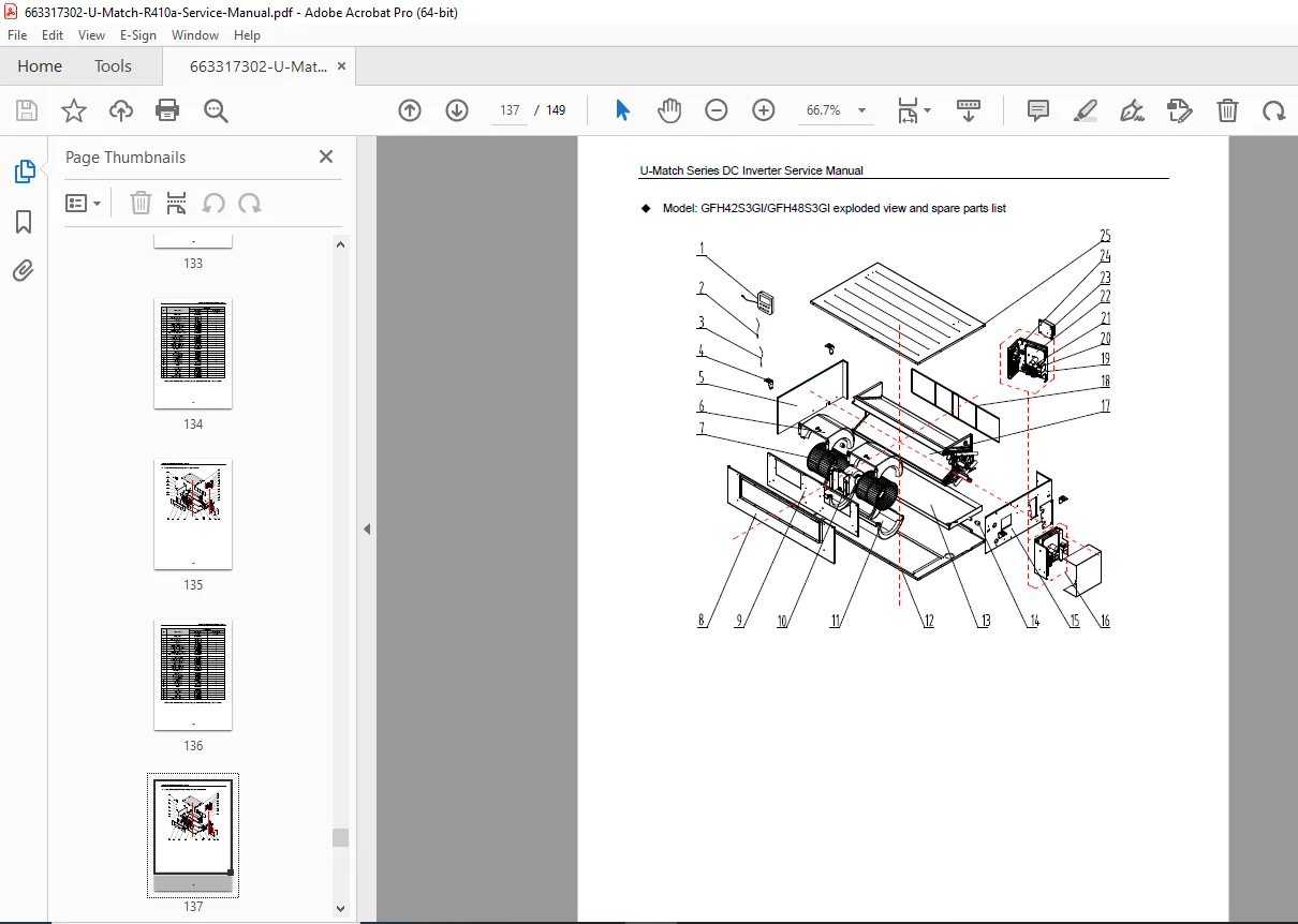
- Duct type exploded view
- Cassette type exploded view
- Component identification
- Part numbers
- Assembly sequence
Spare Parts List:
Outdoor Unit Parts:
- Compressor (model specific)
- Fan motor
- Fan blade
- Four-way valve
- Electronic expansion valve (EEV)
- Control PCB
- IPM module
- Reactor/choke
- Capacitors
- Sensors (all types)
- Pressure switches
- Service valves
- Refrigerant filter-drier
- Heat exchanger (condenser)
- Casing panels
- Hardware kits
Indoor Unit Parts (Duct Type):
- Blower motor
- Blower wheel
- Control PCB
- Display PCB
- Electronic expansion valve
- Sensors
- Air filters
- Drain pan
- Heat exchanger (evaporator)
- Casing components
- Hardware
Indoor Unit Parts (Cassette Type):
- Blower motor
- Blower wheel
- Control PCB
- Display PCB/receiver
- Electronic expansion valve
- Louver motors
- Louvers (all four directions)
- Sensors
- Air filters
- Decorative panel
- Drain pan
- Drain pump (if equipped)
- Heat exchanger (evaporator)
- Casing components
- Hardware
Controllers and Accessories:
- Wireless remote controllers
- Wired wall controllers
- Smart Zone Controller
- Communication cables
- Adapter kits
- Installation brackets
Additional Technical Information
Refrigerant Handling:
- R410A safety precautions
- High-pressure system warnings
- Recovery procedures
- Charging procedures
- Refrigerant purity requirements
- Oil compatibility
Safety Standards:
- Electrical safety compliance
- Refrigerant regulations
- Installation codes
- Service safety procedures
Performance Testing:
- Cooling capacity verification
- Heating capacity verification
- Power consumption measurement
- Superheat/subcooling measurement
- Airflow measurement
- Sound level testing
Preventive Maintenance:
- Filter cleaning schedule
- Heat exchanger cleaning
- Drain cleaning
- Electrical connections inspection
- Refrigerant system inspection
- Control system verification
- Annual maintenance checklist
Who Needs This Manual?
This Gree U-Match DC Inverter service manual is essential for:
- Certified HVAC/R technicians
- Commercial air conditioning contractors
- Gree authorized service centers
- Building maintenance technicians
- Facility management companies
- HVAC service companies
- Anyone performing authorized service on U-Match systems
Prerequisites:
✓ HVAC/R certification (EPA 608 Type II minimum)
✓ R410A refrigerant handling certification
✓ DC inverter system experience
✓ Electrical troubleshooting skills
✓ Understanding of air conditioning principles
✓ Proper tools and test equipment
✓ Safety training for high-pressure refrigerant systems
FILE DETAILS
| Detail | Specification |
|---|---|
| Manual Name | U-MATCH SERIES DC INVERTER AIR CONDITIONERS SERVICE MANUAL |
| Models Covered | U-Match DC Inverter Series (Duct & Cassette Type) |
| Year/Type | Approx. 2016 (T1/R410A) |
| Manufacturer | Gree Electric Appliances Inc. |
| Pages | 149 pages (Based on PDF pagination) |
| PDF Quality | High Digital Quality |
| Language | English |
| Manual Type | Official Factory Service Manual |
| Format | PDF (Digital Download) |