Grove Crane AP 308T WAREHOUSE CRANE 10,000 LB CAPACITY, M469 WHEELED DIESEL Parts Manual – PDF DOWNLOAD
$29.95
Grove Crane AP 308T WAREHOUSE CRANE 10,000 LB CAPACITY, M469 WHEELED DIESEL Parts Manual – PDF DOWNLOAD
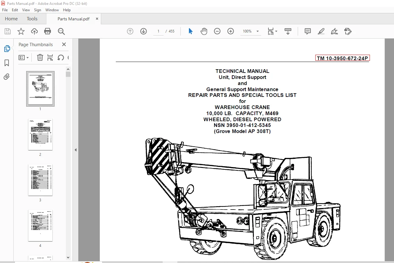
TECHNICAL MANUAL
Unit, Direct Support
and
General Support Maintenance
REPAIR PARTS AND SPECIAL TOOLS LIST
for
WAREHOUSE CRANE
10,000 LB. CAPACITY, M469
WHEELED, DIESEL POWERED
NSN 3950-01-412-5345
(Grove Model AP 308T)
Description
Grove Crane AP 308T WAREHOUSE CRANE 10,000 LB CAPACITY, M469 WHEELED DIESEL Parts Manual – PDF DOWNLOAD
FILE DETAILS:
Grove Crane AP 308T WAREHOUSE CRANE 10,000 LB CAPACITY, M469 WHEELED DIESEL Parts Manual – PDF DOWNLOAD
Language : English
Pages : 455
Downloadable : Yes
File Type : PDF
IMAGES PREVIEW OF THE MANUAL:
DESCRIPTION:
Grove Crane AP 308T WAREHOUSE CRANE 10,000 LB CAPACITY, M469 WHEELED DIESEL Parts Manual – PDF DOWNLOAD
TECHNICAL MANUAL
Unit, Direct Support
and
General Support Maintenance
REPAIR PARTS AND SPECIAL TOOLS LIST
for
WAREHOUSE CRANE
10,000 LB. CAPACITY, M469
WHEELED, DIESEL POWERED
NSN 3950-01-412-5345
(Grove Model AP 308T)
INTRODUCTION:
1. SCOPE:
This manual lists and authorizes spares and repair parts; special tools; special test,
measurement, and diagnostic equipment (TMDE); and other special support equipment required
for performance of unit, direct support and general support maintenance with depot maintenance
of the 10K Warehouse Truck Crane, M469. It authorizes the requisitioning, issue, and disposition
of spares, repair parts, and special tools as indicated by the source, maintenance,
and recoverability (SMR) codes.
2. GENERAL:
This Repair Parts and Special Tools List is divided into the following sections:
by this RPSTL for use in the performance of maintenance. This list also includes parts
which must be removed for replacement of the authorized parts. Parts lists are composed of
functional groups in ascending item number sequence, with the parts in each group listed in
ascending item number sequence. Figure numbers are listed directly beneath the group header. Bulk
materials are listed in item name sequence. Repair parts kits are listed separately in their own
functional group within Section II. Repair parts for reparable special tools are also
listed in this section. Items listed are shown on the associated illustration.
other special support equipment authorized by this RPSTL as indicated by Basis of Issue
(BOI) information (column (5)) for the performance of maintenance.
Number (NIIN) sequence, of all National stock numbered items appearing in the listing, followed
by a list in alphanumeric sequence of all part numbers appearing in the listings. National stock
numbers and part numbers are cross-referenced to each illustration figure and item number
appearance. The figure number and item number index lists figure and item numbers in numeric
sequence
and cross-references National stock number. Commercial and Government Entity Code, and part
numbers.
TABLE OF CONTENTS:
Grove Crane AP 308T WAREHOUSE CRANE 10,000 LB CAPACITY, M469 WHEELED DIESEL Parts Manual – PDF DOWNLOAD
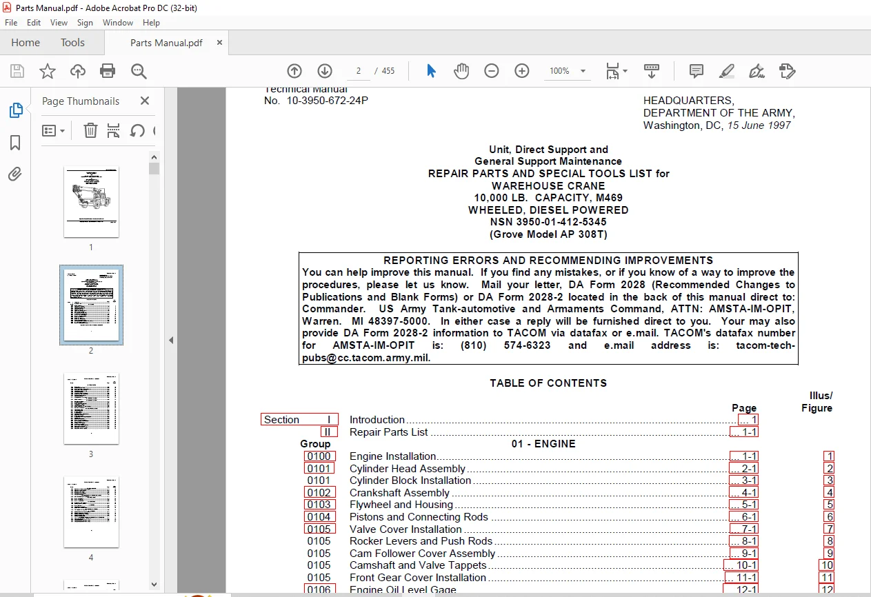
Section I Introduction 1
II Repair Parts List 1-1
Group 01 – ENGINE
0100 Engine Installation 1-1 1
0101 Cylinder Head Assembly 2-1 2
0101 Cylinder Block Installation 3-1 3
0102 Crankshaft Assembly 4-1 4
0103 Flywheel and Housing 5-1 5
0104 Pistons and Connecting Rods 6-1 6
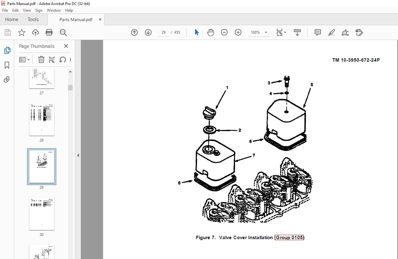
0105 Valve Cover Installation 7-1 7
0105 Rocker Levers and Push Rods 8-1 8
0105 Cam Follower Cover Assembly 9-1 9
0105 Camshaft and Valve Tappets 10-1 10
0105 Front Gear Cover Installation 11-1 11
0106 Engine Oil Level Gage 12-1 12
0106 Engine Oil Cooler 13-1 13
0106 Engine Oil Pan Installation 14-1 14
0106 Engine Oil Pump Installation 15-1 15
0108 Air Intake Manifold and Gasket w/Heater Assy 16-1 16
0108 Exhaust Manifold Installation 17-1 17
0109 Front Gear Train Accessory Drive 18-1 18
Approved for public release: Distribution is unlimited
03 – FUEL SYSTEM
0301 Fuel Injectors 19-1 19
0302 Fuel Lift Pump and Lines 20-1 20
0302 Fuel Injection Pump w/Shutoff Valve Inst 21-1 21
0302 Fuel Injection Pump Assembly 22-1 22
0304 Air Cleaner Assembly and Inst 23-1 23
0306 Fuel Tank Installation 24-1 24
0306 Low Pressure Engine Fuel Lines 25-1 25
0306 High Pressure Engine Fuel Lines 26-1 26
0309 Fuel Filter/Water Separator 27-1 27
0311 Cold Start Installation 28-1 28
0312 Accelerator Pedal and Linkage 29-1 29
04 – EXHAUST SYSTEM
0401 Muffler Installation 30-1 30
05 – COOLING SYSTEM
0501 Fan Guard Installation 31-1 31
0501 Radiator Installation 32-1 32
0503 Engine Water Inlet Connection 33-1 33
0503 Thermostat and Housing 34-1 34
0504 Water Pump Installation 35-1 35
0505 Engine Cooling Fan and Drive Assembly 36-1 36
0505 Fan Belt and Tensioner 37-1 37
06 – ELECTRICAL SYSTEM
0601 Alternator Installation 38-1 38
0601 Alternator Assembly 39-1 39
0603 Starter Installation 40-1 40
0603 Starter Assembly 41-1 41
0607 Cab Main Control Panel Assembly 42-1 42
0607 Relay Panel Installation 43-1 43
0607 Fuse Panel Assembly 44-1 44
0609 Exterior Lights and Turnsignal Installation 45-1 45
0609 Spotlight Inst 46-1 46
0609 Boom Lights Installation 47-1 47
0610 Engine Senders and Switches 48-1 48
0611 Horn and Backup Alarm Installation 49-1 49
0612 Battery Installation 50-1 50
0613 Carrier Harness Assembly 51-1 51
0613 Cab Harness Assembly 52-1 52
0613 Front Console Harness Assembly 53-1 53
0613 Boom Harness Assembly 54-1 54
0613 Boom Lights Harness Assembly 55-1 55
0613 Relay Panel Harness Assembly 56-1 56
07 – TRANSMISSION
0705 Transmission Shifting Lever Installation 57-1 57
0705 Transmission Shift Modulator 58-1 58
0710 Transmission Installation 59-1 59
0710 Transmission Assembly 60-1 60
0710 Park Brake Lever Installation 61-1 61
0710 Park Brake Installation 62-1 62
09 – PROPELLER AND PROPELLER SHAFTS
0900 Drive Line Assembly and Installation 63-1 63
10 – FRONT AXLE
1000 Front Axle Installation 64-1 64
1000 Front Axle Assembly 65-1 65
1002 Front Axle Differential 66-1 66
11 – REAR AXLE
1100 Rear Axle and Hub Installation 67-1 67
1104 Steering Cylinder Assembly 68-1 68
12 – BRAKES
1202 Front Brake Parts 69-1 69
1204 Master Cylinder Installation 70-1 70
1204 Service Brake Lines Installation 71-1 71
13 – WHEELS AND TRACKS
1313 Tire Assembly and w/Lug Nuts 72-1 72
14 – STEERING
1401 Steering Wheel and Control Valve Inst 73-1 73
1401 Steering Control Valve Assembly 74-1 74
1411 Steering Hydraulic Lines Installation 75-1 75
1412 Steering Pump Installation 76-1 76
1412 Steering Pump Assembly 77-1 77
15 – FRAME, TOWING ATTACHMENTS, AND DRAWBARS
1503 Pintle Hook Assembly and Front Tiedown 78-1 78
1507 Outrigger Installation 79-1 79
1507 Outrigger Stabilizer Cylinder Assembly 80-1 80
1507 Outrigger Stabilizer Cylinder Assembly 81-1 81
15 – FRAME, TOWING ATTACHMENTS, AND DRAWBARS – Continued
1507 Outrigger Selector Valves Installation 82-1 82
1507 Outrigger Selector Valve Assembly 83-1 83
18 – BODY, CAB, HOOD, AND HULL
1801 Cab Top Installation 84-1 84
1801 Cab Door Holder Installation 85-1 85
1801 Cab Acoustics Installation 86-1 86
1801 Deck Covers w/Handle Installation 87-1 87
1801 Frame Stud Installation 88-1 88
1806 Seat Installation 89-1 89
22 – BODY, CHASSIS, OR HULL ASSEMBLY ITEMS
2201 Windshield Wiper and Washer Installation 90-1 90
2202 Rearview Mirror w/Deck Post Installation 91-1 91
2207 Cab Heater and Defroster Installation 92-1 92
2207 Cab Circulating Fan Installation 93-1 93
2210 Decal Installation 94-1 94
24 – HYDRAULIC LIFT COMPONENTS
2401 Two-Section Pump Installation 95-1 95
2401 Two-Section Pump Assembly 96-1 96
2402 Hydraulic Lockout/Level Indicator Inst 97-1 97
2402 Hydraulic Control Valves and Linkage 98-1 98
2402 Two-Section Valve Assembly 99-1 99
2402 Three-Section Valve Assembly 100-1 100
2406 Pressure Check Hydraulic Lines Installation 101-1 101
2406 Supply/Pressure/Return Hydraulic Lines 102-1 102
2406 Hydraulic Return Line Filter Assembly 103-1 103
2406 Lift Cylinder Hydraulic Lines Installation 104-1 104
2406 Telescope Cylinder Hydraulic Lines 105-1 105
2406 Swing Drive Hydraulic Lines Installation 106-1 106
2406 Hoist Hydraulic Lines Installation 107-1 107
2406 Outrigger Hydraulic Lines Installation 108-1 108
2406 Swivel Hydraulic Lines Installation 109-1 109
2407 Lift Cylinder Installation 110-1 110
2407 Lift Cylinder Assembly 111-1 111
2407 Lift Cylinder Holding Valve Assembly 112-1 112
2407 Telescope Cylinder Assembly 113-1 113
2407 Telescope Cylinder Holding Valve Assembly 114-1 114
2408 Hydraulic Tank Installation 115-1 115
2408 Hydraulic Oil Cooler Inst w/Fan Assembly 116-1 116
68 – WARNING, SCANNING, AND SIGNALING DEVICES
6801 Antitwo-Block Installation 117-1 117
74 – CRANES, SHOVELS, EARTH MOVING COMPONENTS
7411 Boom Assembly, 2 -Section 118-1 118
7411 Boom Nose Sheave and Cable Retainer 119-1 119
7411 Boom Pivot Pin Installation 120-1 120
7411 Boom Angle Indicator Installation 121-1 121
7411 Hook Block and Latch Assembly 122-1 122
7417 Hoist Installation 123-1 123
7417 Hoist Assembly w/Wedge Socket 124-1 124
7417 Hoist Primary and Secondary Carrier 125-1 125
7417 Hoist Hydraulic Motor Assembly 126-1 126
7417 Hoist Motor Control Valve 127-1 127
7417 Cable Follower Installation 128-1 128
7419 Turntable Bolt Installation 129-1 129
7419 Turntable Drive w/Breather Vent Installation 130-1 130
7419 Swing Drive w/Valve Assembly 131-1 131
7419 Swing Drive Gear Reducer Assembly 132-1 132
7419 Swing Brake Assembly 133-1 133
7419 Swing Motor Assembly 134-1 134
7419 Electric/Hydraulic Swivel Installation 135-1 135
7419 Hydraulic Swivel Assembly 136-1 136
7419 Electric Slip Ring Assembly 137-1 137
76 – FIRE FIGHTING EQUIPMENT COMPONENTS
7638 Fire Extinguisher Installation 138-1 138
Kits 139-1 139
Section III Special Tools List – N/A
Section IV Cross-Reference Indexes
National Stock Number Index I-1
Part Number Index I-13
Figure and Item Number Index I-62
Customer Support: [email protected]
https://vimeo.com/874318444?share=copy
PLEASE NOTE:
- This is the same manual used by the dealers to diagnose and troubleshoot your vehicle
- You will be directed to the download page as soon as the purchase is completed. The whole payment and downloading process will take anywhere between 2-5 minutes
- Need any other service / repair / parts manual, please feel free to contact [email protected] . We still have 50,000 manuals unlisted
S.V