Grove Crane Manitowoc TMS9000-2 Operator Manual – PDF DOWNLOAD
Original price was: $89.95.$29.95Current price is: $29.95.
Grove Crane Manitowoc TMS9000-2 Operator Manual – PDF DOWNLOAD
Description
Grove Crane Manitowoc TMS9000-2 Operator Manual – PDF DOWNLOAD
FILE DETAILS:
Grove Crane Manitowoc TMS9000-2 Operator Manual – PDF DOWNLOAD
Language : English
Pages : 408
Downloadable : Yes
File Type : PDF
Size: 118 MB
DESCRIPTION:
Grove Crane Manitowoc TMS9000-2 Operator Manual – PDF DOWNLOAD
GENERAL:
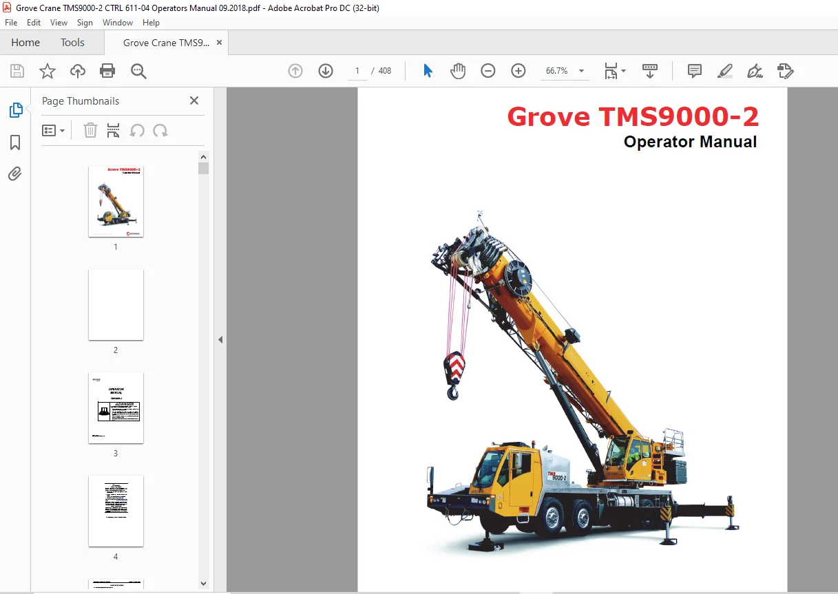
- This manual contains important information for the operator of the Model TMS9000-2 Series Grove Crane.
- The mobile crane carrier features an all-welded steel frame. It is an 8 x 4 x 4 carrier with two drive axles and two steer axles. Axle steering is facilitated by a power steering pump and power steering gear. The engine is located in the front of the carrier and delivers power through an 11-speed forward and 3-speed reverse manual or optional automatic transmission.
- The carrier frame includes hydraulic, two-stage double box telescopic beam outriggers with jack cylinders. The outriggers can be used in four positions: fully extended, mid-extended, partially extended, and fully retracted (100%, 79%, 57%, and 0% respectively). Additionally, the carrier is equipped with a center front jack with a permanently installed pad.
- The superstructure of the crane allows for 360° rotation in either direction. All crane functions are controlled from the fully enclosed cab. The crane is equipped with a five-section boom ranging from 11.2 m to 51.6 m (36.7 ft to 169 ft) in length.
- Lifting capabilities are provided by a main hoist and an auxiliary hoist. The crane also offers options for hydraulically offsettable and manually offsettable boom extensions.
IMAGES PREVIEW OF THE MANUAL:
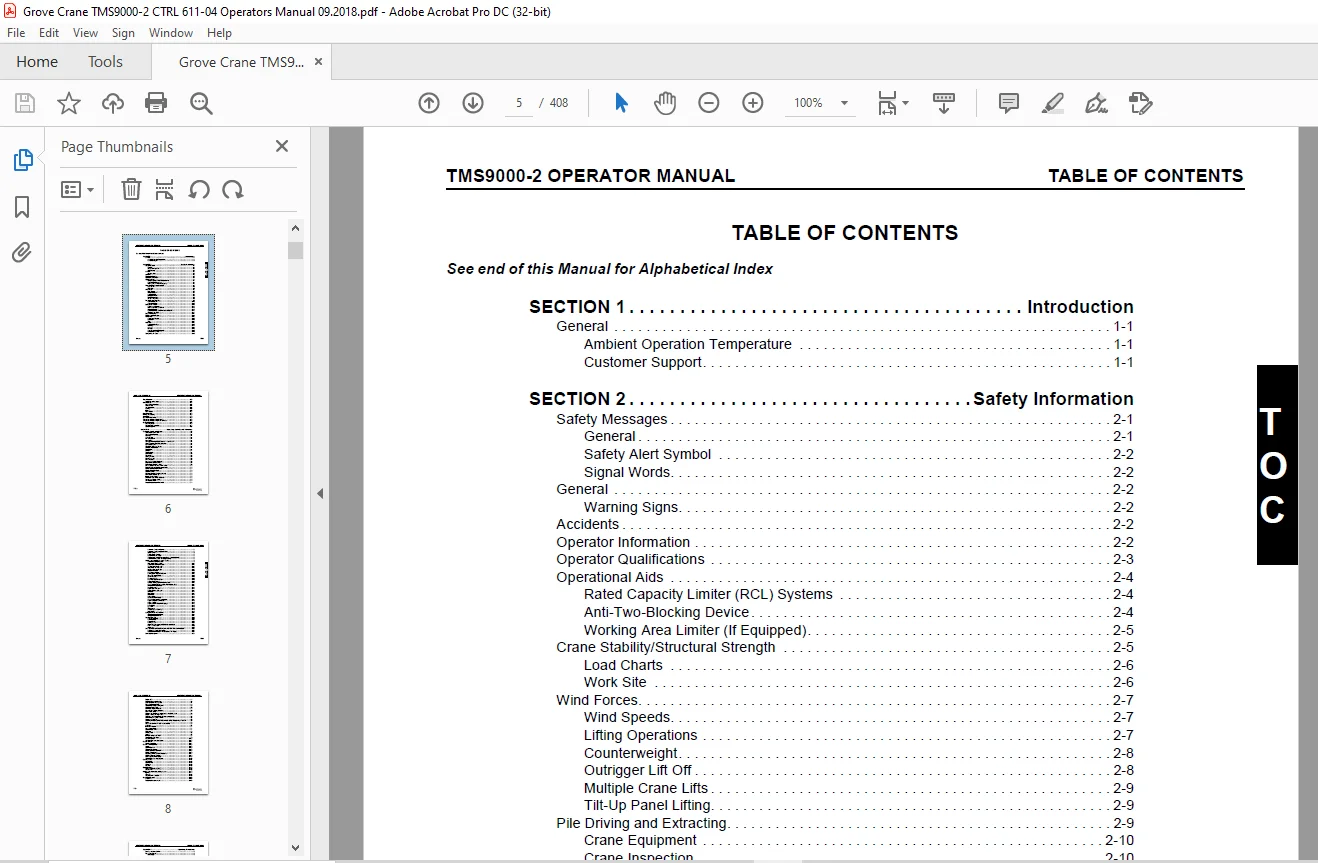
TABLE OF CONTENTS:
Grove Crane Manitowoc TMS9000-2 Operator Manual – PDF DOWNLOAD
See end of this Manual for Alphabetical Index 5
Introduction 13
General 13
Ambient Operation Temperature 13
Customer Support 13
Supplemental Information 13
New Owners 13
Safety Information 17
Safety Messages 17
General 17
Safety Alert Symbol 18
Signal Words 18
General 18
Warning Signs 18
Accidents 18
Operator Information 18
Operator Qualifications 19
Operational Aids 20
Rated Capacity Limiter (RCL) Systems 20
Anti-Two-Blocking Device 20
Working Area Limiter (If Equipped) 21
Crane Stability/Structural Strength 21
Load Charts 22
Work Site 22
Wind Forces 23
Wind Speeds 23
Lifting Operations 23
Counterweight 24
Outrigger Lift Off 24
Multiple Crane Lifts 25
Tilt-Up Panel Lifting 25
Pile Driving and Extracting 25
Crane Equipment 26
Crane Inspection 26
Electrocution Hazard 26
Set-Up and Operation 27
Electrocution Hazard Devices 28
Electrical Contact 28
Special Operating Conditions and Equipment 29
Grounding the Crane 29
Personnel Handling 30
Environmental Protection 31
Maintenance 31
Service and Repairs 31
Lubrication 32
Tires 32
Hoist Rope 32
Synthetic Hoist Rope 32
Wire Rope 33
Sheaves 34
Batteries 34
Super Capacitor (If Equipped) 35
General Maintenance 35
Transporting the Crane 35
Travel Operation 36
Travel with trailing boom 37
Work Practices 37
Personal Considerations 37
Crane Access 37
Job Preparation 37
Working 38
Lifting 38
Hand Signals 39
Boom Extension 41
Parking and Securing 41
Shut-Down 41
Cold Weather Operation 41
Temperature Effects on Hook Blocks 42
Temperature Effects on Hydraulic Cylinders 42
Overload Inspection 43
Boom Inspection 45
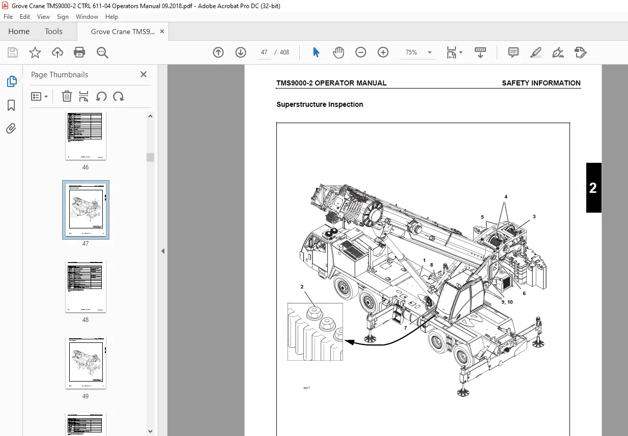
Superstructure Inspection 47
Carrier Inspection 49
Operating Controls and Indicators 51
Carrier Cab Controls and Indicators 53
Transmission Shift Lever 54
Spare Switch/Indicator 54
USB Ports 54
12 Volt Outlet 54
Fire Extinguisher 54
Horn Button 54
Turn Signal/Headlight High Beam Low Beam Lever 54
Steering Column Tilt/Telescope Lever 54
Cab Circulating Fan 54
Windshield Wiper and Washer 54
Carrier Camera Display 54
Dome Light 54
Air Horn 54
Throttle Pedal 54
Brake Pedal 55
Clutch Pedal 55
Steering Wheel 55
Headlights Switch 56
Dimmer Switch 56
Beacon Light Switch (Optional) 56
Engine Brake On/Off Switch 56
Engine Brake High/Low Switch 56
Exhaust System Cleaning Initiate Switch 57
Engine Idle Increment/Decrement Switch 57
Remote Control On/Off Switch 57
Remote Control Indicator 57
ABS/ATC Switch 57
Hill Start Aid (HSA) Switch (Optional) 57
HSA Indicator (Optional) 57
Inter-Axle Lock Switch 57
Cross-Axle Lock Switch (Optional) 57
Suspension Inflation Switch 57
Tire Inflation Switch 57
Heater/Air Conditioner Fan Switch 57
Heater/Air Conditioner Control 58
Heater/Air Conditioner Select Switch 58
Ignition Switch 58
Parking Brake Control 58
Dual Air Pressure Gauge 58
Trailing Boom Trailer Emergency Brake Control (Optional) 58
Control Panel Indicator and Gauge Display 58
Control Panel Indicator and Gauge Display 59
Cross-Axle Locked Indicator 59
Inter-axle Locked Indicator 60
Suspension Deflated Indicator 60
Traction Control Indicator 60
Tire Inflation On Indicator 60
Left Turn Signal Indicator 60
Lights On Indicator 60
High Beam Indicator 60
Parking Brake Engaged Indicator 60
Battery Charge Indicator 60
Low Air Pressure 60
Emergency Stop 60
Right Turn Signal Indicator 60
System Fault Indicator 60
Anti-lock Braking System (ABS) Indicator 60
Check Transmission (Automated Transmission Only) 61
Malfunction Indicator Lamp 61
Low Oil Pressure 61
Engine Stop Indicator 61
Engine Warning Indicator 61
OK Button 61
Menu Button 61
Fuel Gauge 61
Speedometer 61
Low Fuel Level Indicator 61
High Exhaust System Temperature 61
Engine Temperature Indicator 62
Cruise Control 62
Engine Coolant Temperature Gauge 62
Down Button 62
Up Button 62
Tachometer 62
Exhaust System Cleaning 62
LCD Display 62
Outrigger Controls and Indicators 64
Outrigger Control Summary 64
Outrigger Control Panel 64
Outrigger Beam Selector Switch 64
Extend Switch 64
Center Front Jack Switch 65
Jack Selector Switch 65
Emergency Stop Switch 65
Retract Switch 65
Power Indicator 65
Auto Switch 65
Superstructure Cab 66
Superstructure cab 66
Side panel 68
Superstructure cab, rear 69
Control panels 70
Left Hand Armrest Controls 70
Right Hand Armrest Controls 71
Control levers 72
Heating system 73
Operator display module (ODM)/CCS control unit 74
CCS – Home screen 76
Alert Icons 78
Short description of the operating elements of the crane control system 79
Definition of direction information 80
Basic rule 80
On the carrier 80
On the superstructure 80
General rules for buttons and symbols on the display 80
Changing Menus 81
Crane Control System 81
Display CCS 81
Warning message/error message display area 82
Open Error menu 82
Exiting the menu/input mode 82
Enter the values with jog dial 82
Enter values on the control panel CCS 83
Input confirmation 83
Other indicators on the ODM CCS display 83
Display temperature sensor 83
Emergency stop switch 83
To switch displays 83
Settings menu groups 84
Menu for setting the time 85
Switch units menu 87
Set control lever characteristic curve menu 88
Power unit speeds menu 89
Operating hours menu 90
Displaying the operating hours 90
Displays 90
Crane operation error menu 92
Software version menu 93
CCS – Overview menu groups 94
Superstructure lock menu 96
Counterweight menu 97
Outrigger menu 98
Telescoping semi-automation menu 100
Manual telescoping menu 101
ODM Working Range Limiter (WRL) 101
WRL Overall height menu 104
WRL- Boom Angle Limits menu 106
WRL-Working radius menu 108
WRL-Swing angle menu 110
WRL-Virtual walls menu 112
Exhaust System Cleaning menu 114
Bi-fold Boom Extension menu 115
Boom Configurator menu 115
Telescoping emergency program 116
Open Submenu Emergency program 116
Access telescoping emergency program menu 118
Determining the error type 119
Error on length indicator 121
Checks before telescoping 121
Retracting and locking a telescopic section 122
Unlocking the telescoping cylinder 123
Extending and locking the telescoping cylinder 124
Tables for approaching the locking points 124
Locking points for the telescoping cylinder 124
Locking points for the telescopic sections 124
Telescoping cylinder boom nose switch 125
ODM error code viewer 126
RDM (RCL Display Module) 127
Resetting the current telescoping 129
Entering current telescope position values 129
RCL – menu groups 131
Enter rigging mode menu 132
Monitoring menu 134
Outrigger rigging code verification 136
Adjusting the wiper stroke interval of the windshield wiper 136
Display – setting the brightness 137
Setting the characteristic curves for the control levers 138
Crane Functions Speed Control 138
Changing values 139
Operating the camera 139
Switching the camera 139
Switching the boom position indicator light (optional equipment) on and off 139
Engine 140
Side panel 140
Ignition lock 140
Set idling speed 140
Economy mode menu 140
Seat contact switch and dead man’s switches 140
Enabling crane functions 141
Disabling crane functions 141
Superstructure cab seat 141
Outriggers 141
Right-hand control panel 141
Button for outrigger preselection 141
Left-hand control panel 141
Retracting/extending outrigger beams pre-selection 141
In the Outrigger menu 141
Outrigger span display 141
Swing gear/movements locked display 142
Parking brake/movements locked display 142
Function for switching outriggers 142
Extend/retract outrigger beams 143
Extend/retract outrigger jack cylinders 143
Inclination indicator 144
Anemometer display 144
Counterweight menu 144
Counterweight locking display 144
Locking/unlocking the counterweight 145
Extending/retracting the lifting cylinders 145
Pre-tensioning pressure display 145
Main hoist 145
Right control lever 146
Hoist high-speed mode on/off 146
Hoist Speed Range Selection 146
Hoist rotation indicator 146
CCS display 146
Main Hoist Enable 146
High speed mode for the hoist 146
Lift/lower the hoist 147
Warning for lowering limit switch lockout 147
Hoist Limit Lockout Indication 147
Auxiliary hoist 147
Swing 147
Control panels 147
Swing enable 147
Left control lever 147
Free swing button 148
CCS display 148
Swing crane function display 148
Swing brake applied/released 148
Lifting/Lowering mechanism 148
Control panels 148
Lifting/lowering mechanism on/off 148
Right control lever 148
ODM display 149
Lifting/lowering crane function display 149
Boom up override switch 149
Telescoping mechanism 149
Control panels 149
Telescoping enable switch 149
Right control lever 149
Left control lever- Optional 149
Telescoping crane function display 150
Telescoping semi-automation menu 150
Open menu 150
Telescope diagram display 150
Telescoping cylinder length display 150
Main boom length display 151
Telescopic sections display 151
Current telescope status display 151
Pre-selection for all telescopic sections 151
Pre-selection individual telescopic sections 151
Teleautomation direction display 151
Confirm pre-selection 151
Manual telescoping menu 152
Telescoping cylinder locked/released 152
Locking/releasing the telescoping cylinder 152
Lock/release telescopic section indication 152
Locking/releasing the telescopic section 152
Telescoping cylinder length display 153
Main boom length display 153
Telescoping section in the telescopic section display 153
Telescoping direction display 153
Hydraulic system 153
Cab tilt 153
Superstructure house lock menu 153
Swing gear display 154
360 Degree Swing Lock 154
Locking status displays 154
360 Degree Swing Lock 154
Remote control 154
Remote control icon 154
Remote Control Operation 155
Scope 155
System Overview 155
System Components 156
Remote Control Components 158
Display Components 159
Preparing for Remote Control Operation 161
Operating Remote Control 162
Superstructure Horn 162
Emergency Stop 162
Engine Start/Stop/Throttle 163
Starting/Stopping Engine 163
Changing Engine Speed 163
Exiting Start/Stop/Throttle Screen 163
Outrigger Beams 165
Outrigger Jacks 167
Hoist Control (Main and Aux) 169
Boom Lift 171
Swing and 360° Swing Lock 173
Swinging 173
Operating 360° Swing Lock 173
Exiting Swing/360° Swing Lock Screen 173
OPT (options) 175
Luffing Boom Extension 175
Boom Extension Assist 175
Counterweight 175
Exiting OPT Screen 175
Information 176
Rated capacity limiter (RCL) 176
Control unit control console 176
Exiting the menu/input mode 176
Entering values 176
RCL Status Indicators 176
Sensor for brightness 176
Sensor for temperature 177
Display RCL 177
After a standstill of up to 2 hours 177
Enter rigging mode menu 177
Enter RCL code 177
Enter reeving 178
Enter outrigger span 178
Enter counterweight 178
Confirming the rigging mode 179
Boom system entry 179
Monitoring menu 179
Boom system setup display 179
Counterweight display 180
Telescoping Mode Number entry 180
Outrigger span display 181
Display of the lattice extension offset angle 181
Current main boom angle display 181
Current swing angle display 181
Current load display 181
Maximum load display 181
Current degree of utilization display 182
GPL licensing screen 183
Exiting the menu 183
Limits Override 183
Hoist limits override 184
External Limit Bypass Switch 184
External displays 184
Status display 184
Economy Mode 184
Terminology 185
Requirements 185
Operation 186
Benefits 186
Electrical system 186
Voltage monitoring warning 186
Sockets 12 V 186
Lighting, windshield wiper/washing system 187
Lighting 187
Superstructure Cab Work Lights on/off 187
Boom Lights 187
Rotating Boom Lights Control 187
Cab lighting 187
Reading lamp 187
Windshield wiper/washing system 188
Windshield wiper on/off 188
Skylight wiper on/off 188
Windshield/Skylight washing system 188
Wiper stroke interval menu 188
Adjusting the wiper stroke interval 188
Windows 188
Open window (A) 188
Close window (B) 188
Rear window 189
Opening 189
Closing 189
Superstructure cab door 189
From outside 189
Unlock 189
Lock 189
Open/close 189
Inside door operation 190
CraneSTAR® system 190
Overview 190
Position of the components 190
Operating Procedures 193
Breaking-in A New Carrier 194
Pre-Starting Checks 194
Fuel Supply 194
Engine Oil 194
DEF Fluid Level 194
Engine Coolant 195
Batteries 195
Hydraulic Reservoir and Filter 195
Wire Rope 195
Hook Block and Headache Ball 195
Seats 195
Seat Belts 195
Seat Belt Maintenance 195
Cleaning Seat Belt Webbing 195
Signal and Running Lights 195
Service and Parking Brakes 195
Tires 195
Wheels 195
Other Equipment 195
Daily Lubrication 195
Cold Weather Operation 195
Derated capacities for each °F below -40°F 196
Derated capacities for each °C below -40°C 196
Cold Climate Operation 196
Crane Warm-up Procedures 196
Engine 197
Transmission 197
Hoist 197
Swing Drive and Turntable Bearing 197
Axles 197
Hydraulic Oil System 197
Heating and ventilating the superstructure Cab 198
Heating system 198
Switching on 198
Heating System Manual Operation 198
Temperature 199
To increase the temperature 199
To reduce the temperature 199
Fan 199
Increasing the air volume 199
Reducing the air volume 199
Fresh air/recirculated air 199
Fresh air 199
Recirculated air 199
Air distribution 199
Air vents on the windshield and in the center 199
Air vents on the cab floor 200
All air vents 200
Adjusting the air vents 200
Heating System Automatic Operation 201
Setting the day and time 201
Storing the heating start 201
Setting the heating period 201
Switching the heating start on and off 202
Switching off 202
Setting the remaining time 202
Air-conditioning system 202
Switching on 202
Operation 203
Drying the air 203
Switching off 203
Anti-Lock Brake System (ABS) 203
ABS Power-Up Sequence 204
ABS Switch Operation 204
Automatic Traction Control (ATC) Functional Overview 204
ATC Operation 205
System Operation 205
Component Function 205
Traction Control Power-Up Sequence 205
Traction Control Switch Operation 205
Thermal (Brake Heat) Protection 205
ABS/ATC Partial Shutdown 205
Engine Operation 205
Starting Procedure 205
Cold Weather Starting 206
Jump Starting the Crane 206
Charging 206
Idling the Engine 206
Particulate Filter Maintenance at Idle — Unexpected Idle Speed Increase 206
Racing the Engine 207
Shutdown Procedure 207
Exhaust System Cleaning 207
Faults on the DEF system 208
Crane Travel Operation 208
Active Restraints 208
Seat Belts 208
Traveling – General 209
Jobsite Travel Configurations 209
Axle Weight Distribution Table 215
Manual Transmission Clutch Operation 217
Shifting Gears 217
Initial Start-up 218
Upshifting 219
Downshifting 219
Shifting to Reverse 220
Driving Tips 220
Automatic Transmission (Optional) 220
Gear Display 220
Start-up 221
Power Down 221
Reverse Mode 221
Drive Mode 221
MANUAL Mode 222
MANUAL / Hold Mode 222
Transmission Manual Override 222
LOW Mode 223
Transmission LOW Override 223
Hill Start Aid (HSA) (Optional-Only available with automated transmission) 223
Differential Control Switches 224
Operating the Differential Locks 224
Brakes 224
Engine Brake 225
Recommended Crane Shutdown Procedures 225
Unattended Crane 226
Superstructure Cab Platform 226
Proper Leveling of the Crane 226
Bubble Level Adjustment 226
Using the Outriggers 226
Setting the Outriggers 226
Auto Level Procedure 227
Engaging the Partial/Mid Extension Lock Pin 227
Outrigger Monitoring System (OMS) CCS Display 228
Stowing the Outriggers 228
Stowing the Partial/Mid Extension Lock Pin 228
Stowing the Center Front Jack 229
Crane operation 229
Before operating the crane 229
Checking the position of the hoist ropes 230
Checking the electrical system 230
Adjusting the crane cab seat and front control panel 230
Crane cab seat 230
Front panel 231
Checking operator aids 231
Rated capacity limiter 231
Anti-two block switch 231
Emergency stop switch 232
Seat contact switch 232
Preheating the hydraulic oil 233
Using the swing system 233
Switching the 360° lock on/off 233
Switching on the 360° lock 233
Switching off the 360° lock 233
Operation of the rated capacity limiter 234
Switch on the RCL 234
Switching on 234
Lamp test 234
After a standstill of up to 2 hours 235
After a standstill of more than 2 hours 235
Enter rigging mode 236
Entering individual components 236
Switching on input mode 236
Selecting values 237
Counterweight 237
Boom system 238
Outrigger span display 238
Outrigger span 238
Swing range 239
Entering the RCL code 239
Entering the reeving 240
Accepting the rigging code 240
Confirming and applying the rigging code 240
Entering the Telescoping Mode Number 241
Checks before operating the crane 241
Open the menu 241
Checks 241
Hoists display 242
Example of how to switch over the display 242
Displays during crane operation 242
The current overall height 242
The current lattice extension angle 243
The current lattice extension length 243
The counterweight 243
The current swing angle 243
The currently raised load 244
The maximum load 244
The degree of utilization 244
RCL early warning 244
RCL shutdown 244
Shutdown due to overload 244
Canceling a shutdown 245
Display in the event of errors 245
RCL override 245
External Light Bar (Optional) 246
When rigging 246
RCL override 246
Anti-two block switch override 246
After overriding 246
Canceling the override 246
To raise the boom 246
Raise main boom 246
Switch off function 247
In emergencies 247
Canceling a shutdown 247
Canceling the override 247
Crane operation with main boom 247
Main hoist 247
Switching on the main hoist 248
Lifting and lowering 248
Switching off the main hoist 249
Auxiliary hoist 249
Switching on the auxiliary hoist 249
Lifting and lowering 249
Switching off the auxiliary hoist 250
Anti-Two Block switch and lowering limit switch 250
Anti-Two Block 250
Anti-two block switch override 251
Switching on the lifting/lowering mechanism 251
Raising and lowering 252
Switching off the lifting/lowering mechanism 252
Telescoping mechanism 252
Manual telescoping 252
Telescoping with semi-automation 252
Extending with the main boom configuration 252
Overview 252
Telescoping process 253
Assignment for display 255
Fixed length, intermediate length, telescoping length 255
Main boom fixed length 255
Main boom intermediate length 256
Main boom telescoping length 256
Telescoping 256
Telescoping sequence 256
Inspections prior to starting operations 256
Switching on the telescoping mechanism 256
Function of the control lever 256
With telescoping assigned to the right-hand lever 257
With telescoping assigned to the left-hand lever 257
Switching off the telescoping mechanism 257
Manual telescoping 257
Checking the initial position 258
Current telescoping 258
Position of the telescoping cylinder 258
Position of the locking pins 258
Unlocking the telescoping cylinder 259
Prerequisites 259
Unlock 259
Extending/retracting the telescoping cylinder 259
Prerequisites 259
Extending/retracting 259
Lock telescoping cylinder 260
Prerequisites 260
Lock 260
Unlocking the telescopic section 260
Prerequisites 261
Unlock 261
Telescoping the telescopic section 261
Prerequisites 261
Telescoping 261
Locking the telescopic section 262
Prerequisites 262
Lock 262
Locking the telescopic section for on-road driving 262
Telescoping with semi-automation 262
Semi-auto Mode 263
Introduction 263
Semi-auto Mode basic operating procedures 264
Semi-auto Mode for shifting cylinder within fully retracted boom 266
Semi-auto Mode requiring boom to be retracted 266
Semi-auto Mode screen refresh 267
Semi-auto Mode warning indications 267
Semi-auto Mode telescoping function shut-down 267
Semi-auto Mode lost boom configuration 268
Reset telescoping configuration 268
Semi-auto Mode vs Manual Mode 269
Boom Configurator 270
High-speed mode 272
Hoists 272
To switch on high speed mode briefly 272
Continuous operation 272
Swing gear 272
Swing brake 272
Switching on the swing gear 272
Releasing the swing brake 273
Applying the swing brake 273
Swing 273
Releasing locked swing gear 273
Braking the swing movement 274
Free swing mode 274
Switching off the swing gear 275
Possible movement combinations 275
Settings and displays for crane operation 275
Inclining the crane cab 275
Switching units of measure 275
Setting the characteristic curves for the control levers 276
Limiting the power unit speeds 277
Changing values 277
Carrier Camera Display Setup 278
Using the slewable spotlights 278
Warnings in the start menu 279
Meaning of the symbols 279
mechanical emergency unlocking and locking of the telescopic sections 279
Prerequisites 280
Maintenance 280
Unlocking Telescopic Sections 280
Locking Telescopic Sections 281
Work break 281
In case of short work breaks 281
In case of work breaks of more than 8 hours 281
To secure the truck crane 281
Trailing Boom Carrier Option 282
Description 282
Operation 283
Preparation for Highway Travel 283
Travel Precautions 285
Returning to Normal Crane Operation 285
Parking the Trailing Boom Carrier 285
Tilt-Up Panel Procedure Using the Heavy Duty Boom Extension 285
Lubrication 287
General 287
Environmental Protection 287
Cummins Oil Registration List 287
Arctic Conditions Below -18° C (0° F) 288
Lubrication Points 288
Standard Lubricants 289
Cold Weather Lubricants 291
Arctic Lubricants and Conditions 293
Temperatures Below -9°C (15°F) 293
Cold Weather Package and Lubricants 293
Notes Listed in the Following Tables 293
Drivetrain Lubrication 294
Steering Lubrication 299
Axle Lubrication 299
Outrigger Lubrication 302
Miscellaneous Lubrication 303
Turntable & Cab Tilt Lubrication 304
Hoist Lubrication 307
Turntable Central Lubrication 308
Boom Lubrication 309
Crane Setup 309
Greaseless Boom 309
Monthly Lubrication Work 312
Pins 312
Carwell® Rust Inhibitor 313
Protecting Cranes From Corrosion 313
Cleaning Procedures 313
Inspection and Repair 314
Application 314
Areas of Application 314
Set-up and Installation 319
General 320
Installing Cable On The Hoist 320
Cable Reeving 320
Dead-End Rigging/Wedge Sockets 321
Installing Wedge and Socket 322
Positioning/Removing the Hoist Cable 323
Positioning Hoist Cable 323
Removing Hoist Cable 323
Possible reevings on the main boom 324
With 5 Head Sheaves 324
5-sheave hook block 324
3-sheave hook block 325
1-sheave hook block 325
Hook tackle 326
Auxiliary Boom Nose 326
Rigging work for crane operation with the main boom 330
Rigging 330
Unrigging 331
Removable Counterweight 331
Counterweight versions/combinations 334
Lifting individual counterweight sections 334
Lifting stacked counterweight sections 335
Slinging points at the counterweight sections 336
Rigging the counterweight 336
Prerequisites: 336
Unrigging the counterweight 337
Lower 3,000 lb tray plate on the counterweight platform 337
Check the position of the locking pins for 3000 and 5,000 lb counterweight sections 338
Locking Pin position 338
Assembling counterweight versions/ combinations 339
Procedures 339
Counterweight hoist unit 340
Extending/Retracting the lifting cylinders 341
Pre-charge 341
Automatic mode, rigging 341
Rotating with the rigged counterweight 341
Extending/retracting the lifting cylinders 342
Automatic mode rigging 343
Automatic mode unrigging 344
Cancel automatic mode 345
Unlocking/locking the rear counterweight platform 346
Unlocking 346
Locking 346
Swinging with rigged counterweight 347
Rigging work on the main boom 348
Hook block on the bumper 348
Picking up the hook block 348
Attaching the hook block 348
Hook block on a separate vehicle 348
Picking up the hook block 348
Setting down the hook block 349
Reeving the hoist rope 350
Attaching the rope end clamp 352
Dead-end Rigging 352
Unreeving hoist rope 354
Installing/removing the anti-two block switch 354
Installing the anti-two block switch 354
Removing the anti-two block switch 356
Locking/unlocking the anti-two block switch 358
Locking 358
Removing the lock 358
Anemometer and boom position indicator light 358
Installing 358
Switching the boom position indicator light on and off 359
Removing 359
Other rigging work 359
Cameras for crane operation 359
Camera on the hoists 359
Operating the camera 359
Hoist maintenance platform 360
Slinging points for personal protective equipment 360
Boom Extensions 361
Installing the Folding Boom Extension 362
Securing Extension with Tag Line (Rope) 363
Extension Erecting Warnings and Requirements 363
Erecting Procedure: 35 ft (10 5 m) Base Extension 363
Erecting Procedure: 58 ft (17 7 m) Extension 367
Extension Electrical Connections 373
35 ft (10 5 m) Extension Electrical Connections 373
58 ft (17 7 m) Extension Electrical Connections 373
Disconnect Electrical Connections to the 58 ft (17 7 m) Base Extension 374
Connecting the Anti-Two Block Switch 374
35 ft (10 5 m) Extension Anti-Two Block Installation 374
35 ft (10 5 m) Extension Anti-Two Block Removal 374
58 ft (17 7 m) Extension Anti-Two Block Installation 375
Extension Hydraulic Connections (Optional Hydraulic Extension) 375
Checking the Locking Device on the Hose Drum 375
Unlocking the Drum 375
Locking the Drum 375
Hydraulic Hose Installation 376
Position for Main Boom Operation 376
Establishing the Hydraulic Connection 377
Disconnecting the Hydraulic Connection 377
Folding Deflection Sheaves 377
Deploying the Rear Deflection Sheave 377
Stowing Rear Deflection Sheave 378
Positioning/Removing the Hoist Cable 378
Positioning Hoist Cable 378
Removing Hoist Cable 378
Mechanical Luffing Boom Extension (Adjustable Boom Extension) 380
Extension Angle Adjusting Mechanism 380
Setting the Offset Angle with an Auxiliary Crane 380
Setting the Offset Angle without an Auxiliary Crane 380
Entering the RCL Code 380
Inclining the Crane 381
Stowing the Folding Boom Extension 381
Requirements for Stowing the Boom Extensions 381
Stowing Procedure: 23 ft (7 m) Boom Fly Extension 381
Stowing Procedure: 58 ft (17 7 m) Extension 382
Boom Extension Removal 386
From the side of the main boom 386
From the nose of the main boom 389
Installing and Removing the 26 ft (8 m) Extension Insert 389
Installation 389
Removal 390
Insert Electrical Connection 390
Connecting the 26 ft (8 m) Insert to the Main Boom 390
Disconnecting Main Boom Electrical Connection 391
Connecting the Folding Extension Electrical Circuit 391
Disconnecting the Folding Extension Electrical Circuit 391
Extension Hydraulic Connection 392
Connecting Main Boom Hydraulics 392
Disconnecting Main Boom Hydraulics 392
Connecting the Folding Extension Hydraulics 392
Disconnecting the Folding Extension Hydraulics 393
Folding the Deflection Sheave on the 26 ft (8 m) Extension 393
Folding Out the Deflection Sheave 393
Folding In the Deflection Sheave 394
3 5 m (11 4 ft) Manual off-settable Heavy Duty Boom Extension 394
Description 394
Separating Manual Off-settable Heavy Duty Boom Extension from Lattice Extension 394
Installing Manually Offsetable Heavy Duty Boom Extension 395
Setting Heavy Duty Boom Extension Manual Offset 395
Removing the Manual Offsetable Heavy Duty Extension 395
3 5 m (11 4 ft) Hydraulic off-settable Heavy Duty Boom Extension 396
Description 396
Separating Hydraulic Off-settable Heavy Duty Boom Extension from Lattice Base Extension 396
Removing the Hydraulic Offsetable Heavy Duty Extension 398
Auxiliary Single-Sheave Boom Nose (Optional Equipment) 399
Identification 399
Installing/Removing Auxiliary Single-Sheave Boom Nose 399
Installing Auxiliary Single-Sheave Boom Nose 399
Removing the Auxiliary Single-Sheave Boom Nose 400
Rigging the Auxiliary Single-Sheave Boom Nose 400
Rigging in Transport Position 400
Rigging in Working Position 400
Attaching and Removing Hoist Cable 401
Possible Reeving Methods on the Auxiliary Single-Sheave Boom Nose 401
Anti-two Block Switch 401
In Operation 401
During Transport 401
Raising and Setting Down the Main Boom with Rigged Lattice Extension 401
Telescoping with Rigged Lattice Extension 401
Operating with the Lattice Extension 401
Procedure if the Permissible Wind Speed is Exceeded 401
Anti-two Block Troubleshooting 402
Rear Axle Locking Pins 403
Installing Rear Axle Locking Pins 403
Removing Rear Axle Locking Pins 403
Questions? Email us: [email protected]
PLEASE NOTE:
- This is the SAME exact manual used by your dealers to fix your vehicle.
- The same can be yours in the next 2-3 mins as you will be directed to the download page immediately after paying for the manual.
- Any queries / doubts regarding your purchase, please feel free to contact [email protected]
S.V