Grove Crane RT 600E Series Operator’s & Safety Handbook Manual 6-828-100160 – PDF DOWNLOAD
$18.95
Grove Crane RT 600E Series Operator’s & Safety Handbook Manual 6-828-100160 – PDF DOWNLOAD
Description
Grove Crane RT 600E Series Operator’s & Safety Handbook Manual 6-828-100160 – PDF DOWNLOAD
FILE DETAILS:
Grove Crane RT 600E Series Operator’s & Safety Handbook Manual 6-828-100160 – PDF DOWNLOAD
Language : English
Pages : 82
Downloadable : Yes
File Type : PDF
DESCRIPTION:
Grove Crane RT 600E Series Operator’s & Safety Handbook Manual 6-828-100160 – PDF DOWNLOAD
FOREWORD:
This handbook has been compiled to assist you in properly operating and maintaining your Grove
Crane.
- Before placing the crane in service, take time to thoroughly familiarize yourself with the contents
of this manual. After all sections have been read and understood, retain the manual for future
reference in a readily accessible location. - The Grove Crane has been designed for maximum performance with minimum maintenance. With proper
care, years of trouble-free service can be expected. - Constant improvement and engineering progress makes it necessary that we reserve the right to make
specification and equipment changes without notice. - Grove Worldwide and our Dealer Network want to ensure your satisfaction with our products and
customer support. Your local dealer is the best equipped and most knowledgeable to assist you for
parts, service and warranty issues. They have the facilities, parts, factory trained personnel, and
the information to assist you in a timely manner. We request that you first contact them for
assistance. If you feel you need factory assistance, please ask the dealer’s service management to
coordinate the contact on your behalf. - Engine operating procedures and routine maintenance procedures are supplied in a separate manual
with each crane, and should be referred to for detailed information. - Information in this manual does not replace federal, state, or local regulations, safety codes, or
insurance requirements. - Grove remains committed to providing reliable products that enable users and operators to safely
lift and position loads. Grove has been an industry leader in the incorporation of
operational aids into the design of its cranes. Federal law requires that cranes be
properly maintained and kept in good working condition. The manuals that Grove provides that are
specific for each crane and the manufacturer’s manuals for the operational aids shall be followed.
If an operational aid should fail to work properly, the crane user or owner must assure that repair
or recalibration is accomplished as soon as is reasonably possible.If immediate repair or
recalibration of an operational aid is not possible and there are excep- tional circumstances which
justify continued short-term use of the crane when operational aids are inoperative or mal-
functioning, the following requirements shall apply for continued use or shutdown of the crane:
shall be put back into service as soon as replacement parts, if required, are available and the
repairs and recalibration can be carried out. Every reasonable effort must be made to expedite
repairs and recalibration.
malfunctioning, the designated person responsible for supervising the lifting operations shall
establish procedures for determining load weights and shall ascertain that the weight of the load
does not exceed the crane ratings at the radius where the load is to be handled.
3. When a boom angle or radius indicator is inoperative or malfunctioning, the radius or boom
angle shall be deter- mined by measurement.
device is inoperative or malfunctioning, the designated person responsible for supervising the
lifting operations shall establish procedures, such as assigning an additional signal person to
furnish equivalent protection. This does not apply when lifting per- sonnel in load-line supported
personnel platforms. Personnel shall not be lifted when anti-two block devices are not functioning
properly.
5. When a boom length indicator is inoperative or malfunctioning, the designated person
responsible for supervising the lifting operations shall establish the boom lengths at which
the lift will be made by actual measurements or marking on the boom.
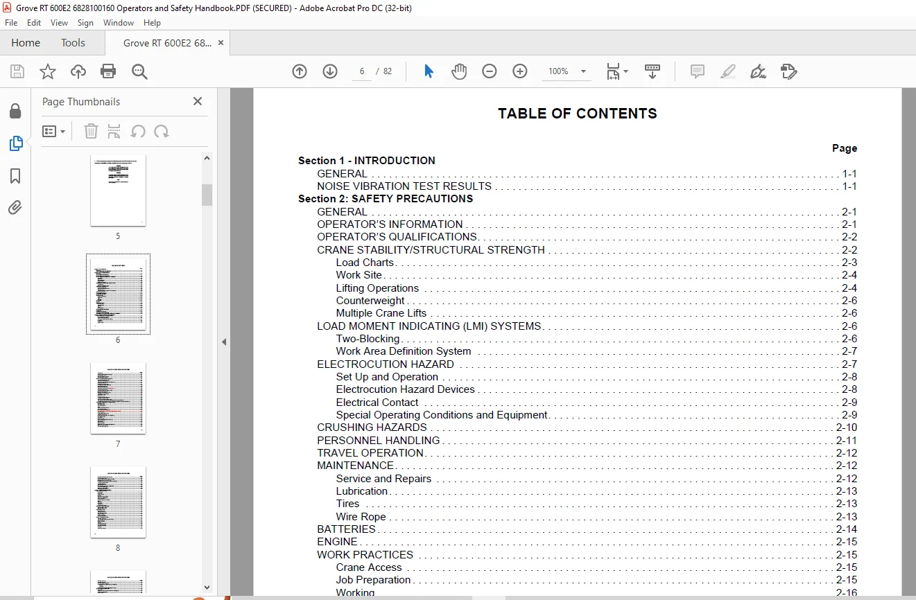
TABLE OF CONTENTS:
Grove Crane RT 600E Series Operator’s & Safety Handbook Manual 6-828-100160 – PDF DOWNLOAD
Section 1 – INTRODUCTION
GENERAL 1-1
NOISE VIBRATION TEST RESULTS 1-1
Section 2: SAFETY PRECAUTIONS
GENERAL 2-1
OPERATOR’S INFORMATION 2-1
OPERATOR’S QUALIFICATIONS 2-2
CRANE STABILITY/STRUCTURAL STRENGTH 2-2
Load Charts 2-3
Work Site 2-4
Lifting Operations 2-4
Counterweight 2-6
Multiple Crane Lifts 2-6
LOAD MOMENT INDICATING (LMI) SYSTEMS 2-6
Two-Blocking 2-6
Work Area Definition System 2-7
ELECTROCUTION HAZARD 2-7
Set Up and Operation 2-8
Electrocution Hazard Devices 2-8
Electrical Contact 2-9
Special Operating Conditions and Equipment 2-9
CRUSHING HAZARDS 2-10
PERSONNEL HANDLING 2-11
TRAVEL OPERATION 2-12
MAINTENANCE 2-12
Service and Repairs 2-12
Lubrication 2-13
Tires 2-13
Wire Rope 2-13
BATTERIES 2-14
ENGINE 2-15
WORK PRACTICES 2-15
Crane Access 2-15
Job Preparation 2-15
Working 2-16
Lifting 2-16
Hand Signals 2-17
TRANSPORTING THE CRANE 2-18
SHUTDOWN 2-18
BOOM EXTENSION/JIB 2-18
COLD WEATHER OPERATION 2-19
TEMPERATURE EFFECTS ON HYDRAULIC CYLINDERS 2-20
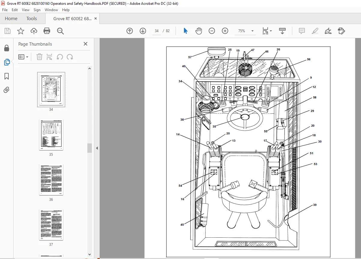
Section 3 – CAB CONTROLS AND INDICATORS
ENGINE CONTROLS AND INDICATORS 3-1
Hand Throttle Lock Control 3-1
Engine Oil Pressure Gauge 3-1
Transmission Oil Temperature Gauge 3-1
Fuel Gauge 3-1
Voltmeter 3-1
Ignition Switch 3-1
vii
TABLE OF CONTENTS (CONTINUED)
Page
Tachometer 3-4
Engine Coolant Temperature Gauge 3-4
Foot Throttle Pedal 3-4
Drivetrain Distress Indicator 3-4
Hourmeter (Not Shown) 3-4
CRANE CONTROLS AND INDICATORS 3-4
Crane Function Power Switch 3-4
Transmission Shift Lever 3-4
Telescope or Auxiliary Hoist Control Lever 3-4
Swing Control Lever 3-4
Rear Steer Control Switch 3-4
Auxiliary Hoist Switch (Optional) 3-5
Boom Lift Control Lever 3-5
Main Hoist Control Lever 3-5
Telescope Control Foot Pedal (Optional) 3-5
Hoist Rotation Indicators 3-5
Transmission Range Selector Switch 3-5
Outrigger Selector Panel 3-5
Outrigger Extend/Retract Switch 3-5
Swing Brake Control Switch 3-5
Swing Brake Pedal 3-5
Brake Foot Pedal 3-6
Low Brake Pressure Indicator 3-6
Park Brake Control Switch 3-6
Pin Swing Lock Control (Pin Type) 3-6
360 Degree Swing Lock Control (Positive Lock Type) (Optional) 3-6
Load Moment Indicating (LMI) and Work Area Definition System Control Panel 3-6
ACCESSORY CONTROLS AND INDICATORS 3-6
Headlights Switch 3-6
Work Light Switch 3-6
Cab Circulating Fan 3-6
Horn 3-7
Backup Alarm (Not Shown) 3-7
Hazard Lights Switch 3-7
Boom Light Switch (Optional) 3-7
Turn Signal Lever and Windshield Wiper/Washer Controls 3-7
Cab Dome Light 3-7
Skylight Wiper (Not Shown) 3-7
Bubble Level Indicator 3-7
Air Conditioner Control Switch (Optional) 3-7
Heat Control Knob 3-7
Fan Switch 3-7
Defroster Switch 3-7
Beacon Light (Optional) (Not Shown) 3-8
Fire Extinguisher 3-8
Defroster Fan 3-8
Windshield Wiper 3-8
Differential Lock Control Switch (Optional) 3-8
Right Turn Signal Indicator 3-8
Left Turn Signal Indicator 3-8
viii
TABLE OF CONTENTS (CONTINUED)
Page
Rear Wheels Not Centered Indicator 3-8
Hydraulic Boost Switch 3-8
Hoist 3rd Wrap Indicator (Optional w/CE) 3-8
Main Hoist Speed Selector Switch 3-9
Auxiliary Hoist Speed Selector Switch (Optional) 3-9
12 VDC Accessory Outlet 3-9
Spotlight (Optional) 3-9
Circuit Breaker Panel 3-9
Drivetrain Dkstress Indicator (CE Units) 3-9
Anemometer (CE Units) 3-9
Emergency Exit (CE Units) 3-9
Wait-To-Start Indicator 3-9
Section 4 – OPERATING PROCEDURES
PRE-STARTING CHECKS 4-1
Fuel Supply 4-1
Engine Oil 4-1
Engine Coolant 4-1
Batteries 4-1
Signal and Running Lights 4-1
Foot and Parking Brakes 4-1
Daily Lubrication 4-1
Hydraulic Reservoir and Filter 4-1
Tires 4-1
Wire Rope 4-1
Hook Block 4-1
Air Cleaner 4-1
Access Hole Covers 4-1
COLD WEATHER OPERATION 4-2
Operation Below -40°C 4-2
Operation Below -40°F 4-2
ENGINE OPERATION 4-2
Battery Disconnect 4-2
Starting Procedure 4-2
Cold Weather Starting 4-2
Idling the Engine 4-3
Racing the Engine 4-3
Shutdown Procedure 4-3
CRANE TRAVEL OPERATION 4-3
Traveling – General 4-3
Traveling With Boom Extension Erected 4-4
Extended Travel 4-4
Moving the Crane 4-5
Steering 4-5
Front Wheel Steering 4-5
Rear Wheel Steering 4-5
Four Wheel Steering 4-5
Crabbing 4-5
Secondary Steering 4-5
ix
TABLE OF CONTENTS (CONTINUED)
Page
Traveling – Forward 4-6
Traveling – Reverse 4-6
Four-Wheel Drive Operation 4-6
Proper Operation Of Differential Lock (Optional) 4-6
General 4-7
Operation 4-7
Proper Operation Of Axle Oscillation Lockouts 4-8
GENERAL CRANE OPERATION 4-8
Pump Drive 4-8
Setting the Park Brake When Crane is on Outriggers 4-8
Control Lever Operation 4-8
Preload Check 4-8
USING YOUR LOAD CHART 4-9
CRANE FUNCTIONS 4-10
Setting the Outriggers 4-10
Engaging the Mid-Extend Lock Pin 4-11
Setting the Outriggers (CE Units) 4-11
Stowing the Outriggers 4-11
Stowing the Mid-Extend Lock Pin 4-12
Stowing the Outirggers (CE Units) 4-12
Swinging the Boom 4-12
Elevating and Lowering the Boom 4-12
Elevating the Boom 4-12
Lowering the Boom 4-12
Telescoping the Boom 4-13
Extending the Boom 4-13
Retracting the Boom 4-13
Telescope Control Pedal 4-13
Lowering and Raising the Cable 4-13
Lowering the Cable 4-13
Raising the Cable 4-13
Hoist Speed Range Selection 4-13
Operational Aids 4-14
Load Moment Indicator (LMI) System 4-14
CE Units 4-14
Control Lever Lockout System 4-14
Stowing and Parking 4-15
Section 5 – LUBRICATION
GENERAL 5-1
Arctic Conditions – Below -18°C (0°F) 5-1
LUBRICATION POINTS 5-1
WIRE ROPE LUBRICATION 5-8
Section 6 – SET-UP AND INSTALLATION PROCEDURES
GENERAL 6-1
INSTALLING CABLE ON THE HOIST 6-1
CABLE REEVING 6-1
DEAD-END RIGGING/WEDGE SOCKETS 6-5
Installing Wedge and Socket 6-5
ERECTING AND STOWING THE BOOM EXTENSION 6-7
Erecting 6-7
Stowing 6-11
Setting the Offset 6-12
Changing Swingaway Boom Extension From Telescoping Type To Fixed Type 6-12
Setting The Telescoping Swingaway Length 6-13
Extending 6-13
Retracting 6-13
IMAGES PREVIEW OF THE MANUAL:
Questions? Email us: [email protected]
PLEASE NOTE:
- This is the same manual used by the dealers to diagnose and troubleshoot your vehicle
- You will be directed to the download page as soon as the purchase is completed. The whole payment and downloading process will take anywhere between 2-5 minutes
- Need any other service / repair / parts manual, please feel free to contact [email protected] . We still have 50,000 manuals unlisted
S.V