Grove Crane RT 9000E Series Operator’s & Safety Handbook Manual PDF
$24.95
Grove Crane RT 9000E Series Operator’s & Safety Handbook Manual – PDF DOWNLOAD
Description
Grove Crane RT 9000E Series Operator’s & Safety Handbook Manual – PDF DOWNLOAD
FILE DETAILS:
Grove Crane RT 9000E Series Operator’s & Safety Handbook Manual – PDF DOWNLOAD
Language : English
Pages : 102
Downloadable : Yes
File Type : PDF
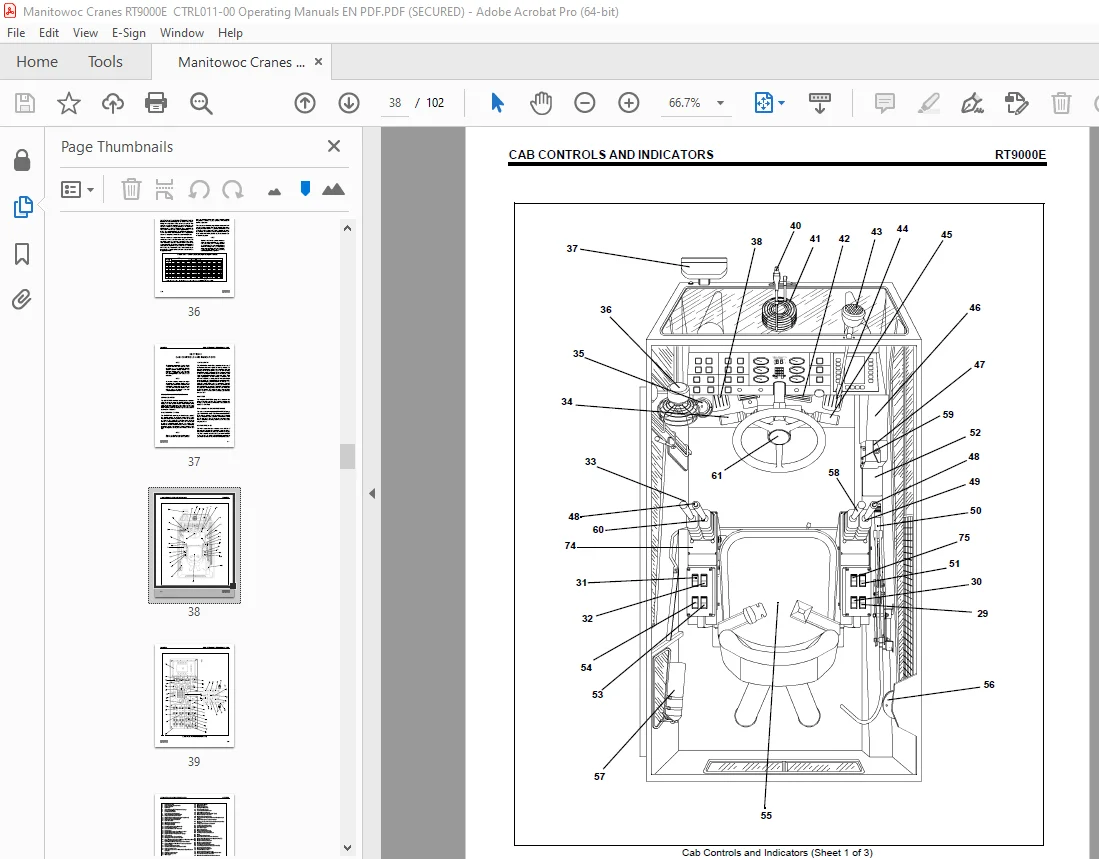
IMAGES PREVIEW OF THE MANUAL:
TABLE OF CONTENTS:
Grove Crane RT 9000E Series Operator’s & Safety Handbook Manual – PDF DOWNLOAD
Section 1 – INTRODUCTION
GENERAL 1-1
NOISE VIBRATION TEST RESULTS 1-1
Section 2: SAFETY PRECAUTIONS
GENERAL 2-1
OPERATOR’S INFORMATION 2-1
OPERATOR’S QUALIFICATIONS 2-2
CRANE STABILITY/STRUCTURAL STRENGTH 2-2
Load Charts 2-3
Work Site 2-4
Lifting Operations 2-4
Counterweight 2-6
Multiple Crane Lifts 2-6
LOAD MOMENT INDICATING (LMI) SYSTEMS 2-6
Two-Blocking 2-6
Work Area Definition System 2-7
ELECTROCUTION HAZARD 2-7
Set Up and Operation 2-8
Electrocution Hazard Devices 2-8
Electrical Contact 2-9
Special Operating Conditions and Equipment 2-9
CRUSHING HAZARDS 2-10
PERSONNEL HANDLING 2-11
TRAVEL OPERATION 2-12
MAINTENANCE 2-12
Service and Repairs 2-12
Lubrication 2-13
Tires 2-13
Wire Rope 2-13
BATTERIES 2-14
ENGINE 2-15
WORK PRACTICES 2-15
Crane Access 2-15
Job Preparation 2-15
Working 2-16
Lifting 2-17
Hand Signals 2-18
TRANSPORTING THE CRANE 2-18
SHUTDOWN 2-19
BOOM EXTENSION/JIB 2-19
COLD WEATHER OPERATION 2-19
TEMPERATURE EFFECTS ON HYDRAULIC CYLINDERS 2-20
Section 3 – CAB CONTROLS AND INDICATORS 3-1
Defroster Switch 3-1
Hand Throttle Lock Control 3-1
Ignition Switch 3-1
Voltmeter 3-1
Transmission Oil Temperature Gauge 3-1
Heat Control Knob 3-1
viii
TABLE OF CONTENTS (CONTINUED)
Page
Fan Control Switch 3-4
Park Brake Control Switch 3-4
Air Conditioner Control Switch 3-4
Swing Brake Control Switch 3-5
Differential Lock Control Switch (Optional) 3-5
Swing Speed Control Switch 3-5
Drive Axle Selector Switch 3-5
Cab Tilt Switch 3-5
Outrigger Control Switches 3-5
Work Light Switch 3-5
Headlights Switch 3-5
Boom Lights Switch (Optional) 3-6
Hazard Lights Switch 3-6
Hose Reel Brake On Indicator 3-6
Fuel Gauge 3-6
Engine Diagnostics Switches 3-6
Test Mode Switch 3-6
Idle Switch 3-6
Engine Coolant Temperature Gauge 3-6
Tachometer 3-6
Crane Function Power Switch 3-6
Outriggers Extend/Retract Switch 3-6
Load Moment Indicating (LMI) and Work Area Definition System Control Panel 3-7
Auto/Manual Boom Telescope Mode Switch 3-7
Center Mid/Inner Mid Boom Telescope Section Select Switch 3-7
Rear Steer Control Switch 3-7
Auxiliary Hoist Speed Selector Switch 3-7
Swing Control Lever 3-7
Turn Signal Lever and Windshield Wiper/Washer Controls 3-7
Bubble Level Indicator 3-8
Cab Circulating Fan 3-8
Swing Brake Pedal 3-8
Telescope Control Foot Pedal 3-8
Windshield Wiper 3-8
Defroster Fan 3-8
Brake Foot Pedal 3-8
Spotlight (Optional) 3-8
Foot Throttle Pedal 3-8
Transmission Shift Lever 3-8
Circuit Breaker Panel 3-8
Pin Swing Lock Control (Pin Type) 3-8
Hoist Rotation Indicators 3-9
Main Hoist Control Lever 3-9
360 Degree Swing Lock Control (Positive Lock Type) 3-9
Main Hoist Speed Selector Switch 3-9
Engine and System Diagnostic Connector (Not Shown) 3-9
Luffing Jib Raise/Lower Switch 3-9
Luffing Jib On/Off Switch 3-9
Seat Switch (not shown) 3-9
Cab Dome Light 3-9
ix
TABLE OF CONTENTS (CONTINUED)
Page
Fire Extinguisher 3-9
Boom Lift Control Lever 3-9
12 VDC Accessory Outlet 3-9
Auxiliary Hoist Control Lever 3-9
Horn 3-10
Right Turn Signal Indicator 3-10
Left Turn Signal Indicator 3-10
Rear Wheels Not Centered Indicator 3-10
Hoist 3rd Wrap Indicator (Optional W/CE) 3-10
Engine Stop Indicator 3-10
Engine Warning Indicator 3-10
Engine Service Indicator 3-10
Wait to Start Indicator 3-10
Low Brake Pressure Indicator 3-10
Transmission Service Indicator (XMSN) 3-10
Water in Fuel Indicator 3-10
Boom Not Sync Indicator 3-11
Throttle Mode Switch 3-11
Hourmeter (Not Shown) 3-11
Skylight Wiper (Not Shown) 3-11
Backup Alarm (Not Shown) 3-11
Armrest Switch (Not Shown) 3-11
Boom Telescope Mode A/B Select Switch 3-11
Low Steer Pressure Indicator (CE Option) 3-11
Electrical System Diagnostic Indicator 3-11
Section 4 – OPERATING PROCEDURES
PRE-STARTING CHECKS 4-1
Fuel Supply 4-1
Engine Oil 4-1
Engine Coolant 4-1
Batteries 4-1
Signal and Running Lights 4-1
Foot and Parking Brakes 4-1
Daily Lubrication 4-1
Hydraulic Reservoir and Filter 4-1
Tires 4-1
Wire Rope 4-1
Hook Block 4-1
Boom 4-1
Air Cleaner 4-1
COLD WEATHER OPERATION 4-1
Operation Below -40°C 4-2
Operation Below -40°F 4-2
ENGINE OPERATION 4-2
Starting Procedure 4-2
Warm Engine 4-2
Cold Engine 4-3
Idling the Engine 4-3
Racing the Engine 4-3
Shutdown Procedure 4-4
x
TABLE OF CONTENTS (CONTINUED)
Page
CRANE TRAVEL OPERATION 4-4
Traveling – General 4-4
Traveling With Boom Extension and/or Insert Erected 4-4
Extended Travel 4-5
Moving the Crane 4-5
Steering 4-6
Front Wheel Steering 4-6
Rear Wheel Steering 4-6
Four Wheel Steering 4-6
Crabbing 4-6
Traveling – Forward 4-6
Traveling – Reverse 4-7
Four-Wheel Drive Operation 4-7
Proper Operation Of Differential Lock 4-7
General 4-7
Operation 4-8
Proper Operation Of Axle Oscillation Lockouts 4-8
GENERAL CRANE OPERATION 4-8
Pump Drive 4-8
Setting the Park Brake When Crane is on Outriggers 4-8
Control Lever Operation 4-9
Preload Check 4-9
USING YOUR LOAD CHART 4-9
CRANE FUNCTIONS 4-10
Setting the Outriggers 4-10
Engaging the Mid-Extend Lock Pin 4-11
Stowing the Outriggers 4-11
Stowing the Mid-Extend Lock Pin 4-12
Swinging the Boom 4-12
Elevating and Lowering the Boom 4-12
Elevating the Boom 4-12
Lowering the Boom 4-12
Telescoping the Boom 4-13
Extending the Boom 4-13
Retracting the Boom 4-13
Lowering and Raising the Hoist Cable 4-13
Lowering the Cable 4-13
Raising the Cable 4-13
Hoist Speed Range Selection 4-13
Raising and Lowering the Hydraulic Boom Extension 4-14
Raising the Hydraulic Boom Extension 4-14
Lowering the Hydraulic Boom Extension 4-14
Operational Aids 4-14
Load Moment Indicator (LMI) System 4-14
Control Lever Lockout System 4-14
Stowing and Parking 4-14
Section 5 – LUBRICATION
GENERAL 5-1
Artic Conditions – Below – 18°C (0°F) 5-1
LUBRICATION POINTS 5-1
xi
TABLE OF CONTENTS (CONTINUED)
Page
WIRE ROPE LUBRICATION 5-9
Section 6 – SET-UP AND INSTALLATION PROCEDURES
GENERAL 6-1
INSTALLING CABLE ON THE HOIST 6-1
CABLE REEVING 6-1
STANDARD COUNTERWEIGHT AND AUXILIARY HOIST MOUNTING STRUCTURE 6-5
Removal 6-5
Installation 6-5
HEAVY COUNTERWEIGHT ASSEMBLY AND AUXILIARY HOIST MOUNTING STRUCTURE 6-8
Removal 6-8
Installation 6-9
OUTRIGGER REMOVAL AND INSTALLATION 6-10
Bleed Valve Operation 6-10
Procedure 6-10
Removal 6-11
Installation 6-11
ERECTING AND STOWING THE SWINGAWAY BOOM EXTENSION 6-12
Erecting 6-12
Stowing 6-16
CONNECTING AND DISCONNECTING THE HYDRAULIC BOOM EXTENSION 6-17
Connecting 6-17
Disconnecting 6-18
SWINGAWAY MOUNTING ADJUSTMENT 6-18
BOOM EXTENSION (WITH INSERTS) 6-19
Identification 6-19
Slinging Points 6-19
ASSEMBLY OF BOOM EXTENSIONS 6-20
CHECKLISTS FOR RIGGING WORK 6-21
Installing the 26 m/34 m Boom Extension 6-21
Removing the 26 m/34 m Boom Extension 6-22
DESCRIPITON OF RIGGING WORK 6-23
Installing/Disassembling 8 m Sections 6-23
Installing 8 m Sections 6-24
Removing 8 m Sections 6-24
INSTALLING/REMOVING TWO-STAGE SWINGAWAY LATTICE EXTENSION FOR BOOM EXTENSION 6-24
Installation 6-24
Removing 6-25
HYDRAULIC CONNECTION ON THE BOOM EXTENSION (IF UNIT IS EQUIPPED WITH HYDRAULIC
LUFFING BOOM EXTENSION) 6-25
Connections on the 8 m Sections 6-25
ELECTRICAL CONNECTION ON THE BOOM EXTENSION 6-26
Connections on the 8 m Sections 6-26
Establishing Electrical Connections 6-26
FOLDING OUT/IN THE DEFLECTION SHEAVES ON THE 8 M SECTIONS 6-26
POSITIONING/REMOVING THE HOIST CABLE 6-27
S.V 06/24