Grove Crane RT600E Service Manual CTRL 488-01 – PDF DOWNLOAD
$28.95
Grove Crane RT600E Service Manual CTRL 488-01 – PDF DOWNLOAD
Description
Grove Crane RT600E Service Manual CTRL 488-01 – PDF DOWNLOAD
FILE DETAILS:
Grove Crane RT600E Service Manual CTRL 488-01 – PDF DOWNLOAD
Language : English
Pages : 300
Downloadable : Yes
File Type : PDF
IMAGES PREVIEW OF THE MANUAL:
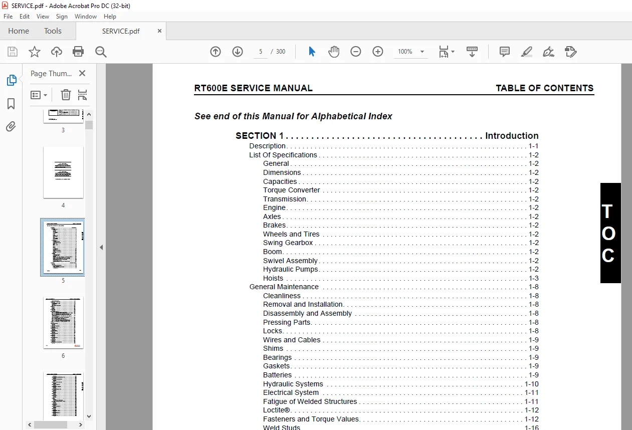
TABLE OF CONTENTS:
Grove Crane RT600E Service Manual CTRL 488-01 – PDF DOWNLOAD
See end of this Manual for Alphabetical Index 5
SECTION 1 13
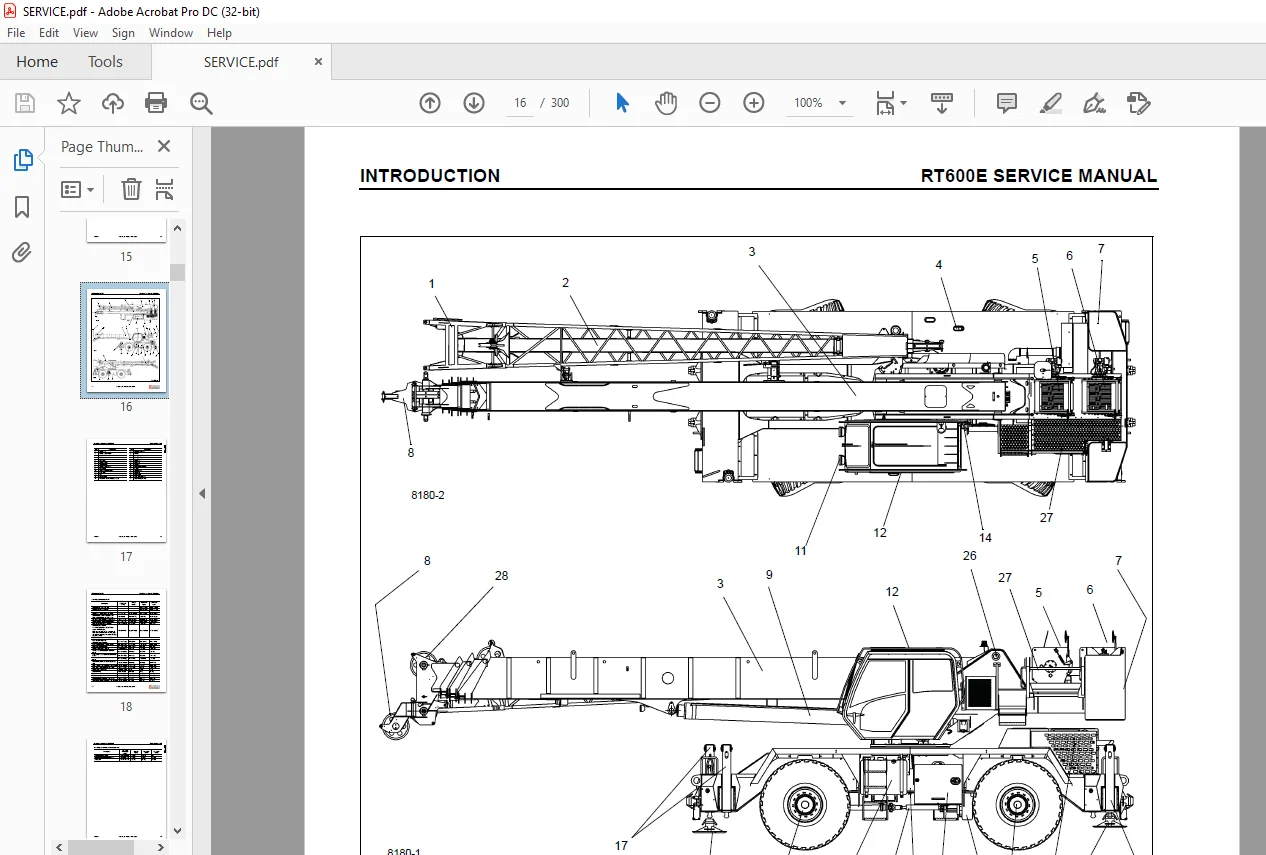
Introduction 13
Description 13
List Of Specifications 14
General 14
Dimensions 14
Capacities 14
Torque Converter 14
Transmission 14
Engine 14
Cummins QSB6 7 14
Axles 14
Brakes 14
Wheels and Tires 14
Swing Gearbox 14
Boom 14
Swivel Assembly 14
Hydraulic Pumps 14
Pump #1 14
Pump #2 14
Pump #3 15
Hoists 15
Axle Weight Distribution Table (Continued) 18
General Maintenance 20
Cleanliness 20
Removal and Installation 20
Disassembly and Assembly 20
Pressing Parts 20
Locks 20
Wires and Cables 21
Shims 21
Bearings 21
Antifriction Bearings 21
Double Row, Tapered Roller 21
Heating Bearings 21
Installation 21
Preload 21
Sleeve Bearings 21
Gaskets 21
Batteries 21
Hydraulic Systems 22
Cleanliness 22
Keep the System Clean 22
Sealing Elements 22
Hydraulic Lines 22
Visual Inspection of Hoses and Fittings 22
Electrical System 23
Cables, Harnesses, Wires, and Connectors 23
Fatigue of Welded Structures 23
Loctite® 24
Application of Medium Strength Loctite 24
Primer Application 24
Adhesive/Sealant Application 24
Fasteners and Torque Values 24
Torque Wrenches 24
Torque Values 25
Weld Studs 28
Wire Rope 29
General 29
Environmental Conditions 29
Dynamic Shock Loads 29
Lubrication 29
Precautions and Recommendations During Inspection or Replacement 29
Wire Rope Inspection (Running Ropes and Pendant Cables) 30
Keeping Records 30
Frequent Inspection 30
Periodic Inspection 31
Wire Rope Inspection (Boom Extension and Retraction Cables) 31
Periodic Inspection 31
Wire Rope Inspection/Replacement (All Wire Rope) 31
Seizing Wire Rope 32
Method 1 32
Method 2 32
Installing 35×7 Class Wire Rope 33
Procedures for Cutting and Preparing 35×7 Class Wire Rope 33
SECTION 2 35
Hydraulic System 35
Description 36
Maintenance 36
Hydraulic Oil Recommendations 36
Draining and Flushing 36
Removing Air from the Hydraulic System 40
Parts Replacement 40
Directional Control Valves 40
Inspection 40
Valve Leakage 40
Binding Spools 41
Visual Inspection of Hoses and Fittings 41
Supply Pressure and Return Circuit 42
Description 42
Hydraulic Reservoir and Filter 42
Pump Distribution 42
No 1 Pump 42
No 2 Pump 43
No 3 Pump 43
Maintenance 44
Troubleshooting 44
Hydraulic Reservoir Removal 45
Hydraulic Reservoir Installation 45
Breather Removal and Replacement 45
Return Hydraulic Filter Assembly 46
Element Removal 46
Element Installation 47
Oil Cooler 48
Description 48
Removal 48
Installation 48
Hydraulic Pumps 49
Description 49
Maintenance 49
No 1 Pump Removal 49
No 1 Pump Installation 49
No 1 Pump and Pump Disconnect Assembly Removal 49
No 1 Pump and Pump Disconnect Assembly Installation 50
No 2 Pump Removal 50
No 2 Pump Installation 52
No 3 Pump Removal 52
No 3 Pump Installation 52
Testing After Repair or Replacement 52
Pressure Setting Procedures 54
Valve Pressure Setting Table 54
Procedure A – For Checking Main Control Valve Reliefs 54
Procedure B – For Checking Directional Control Valve Pilot Supply Pressure 55
Procedure C – For Checking Swing Brake Pilot Supply Pressure 56
Procedure D – For Checking Service Brake and Air Conditioning Circuit Relief Pressure 56
Procedure E- For Checking the Service Brake Dual Accumulator Charge Valve Pressure Limits 57
Procedure F- For Checking Accumulator Pre-Charge Pressure 57
Procedure G- For Pre-charging Accumulator 58
Procedure H – For Checking the Front Steer Pressure 58
Procedure I – For Checking Swing Valve Work Port Relief Pressure 58
Procedure J- For Checking Outrigger and Rear Steer Valve Relief 59
Procedure K – For checking Transmission Oil Cooler Valve Relief 60
Valves 61
General 61
Valve Usage Table (Continued) 61
Directional Control Valves 64
Description 64
Maintenance 64
Swing/Steer Valve Bank Removal 64
Swing/Steer Valve Bank Installation 64
Hoist/Lift/Telescope Valve Bank Removal 64
Hoist/Lift/Telescope Valve Bank Installation 64
Valve Bank Functional Checks 64
Hydraulic Remote Control Valve 68
Description 68
Single Axis Controllers 68
Dual Axis Controllers 68
Maintenance 68
Armrest Control Valve Removal 68
Armrest Control Valve Installation 68
Armrest Control Valve Functional Check 68
Telescope Pedal Control Valve Removal (with Auxiliary Hoist Option) 68
Telescope Pedal Control Valve Installation (with Auxiliary Hoist Option) 68
Telescope Pedal Control Valve Functional Check (with Auxiliary Hoist Option) 70
Outrigger/Rear Steer Valve 71
Description 71
Maintenance 71
Removal 71
Installation 71
Functional Check 71
Outrigger Control Manifold 73
Description 73
Maintenance 73
Removal 73
Inspection 73
Installation 73
Functional Check 73
Pilot Operated Check Valve 75
Description 75
Maintenance 75
Removal 75
Installation 75
Holding Valve 76
Description 76
Maintenance 76
Removal 76
Installation 76
Swing Power Brake Valve 77
Description 77
Maintenance 77
Removal 77
Installation 77
Function Check 77
Throttle Foot Valve 78
Description 78
Maintenance 78
Removal 78
Installation 78
Function Check 78
Tandem Brake Valve with Treadle Pedal 79
Description 79
Maintenance 79
Removal 79
Installation 79
Service Brake Dual Accumulator Charge Valve 80
Description 80
Maintenance 80
Removal 80
Installation 80
Service Brake Hydraulic Accumulator 81
Description 81
Maintenance 81
Removal 81
Installation 81
Servicing 81
Swing Brake and RCL Lockout Valve 82
Description 82
Maintenance 82
Removal 82
Installation 82
Function Check – Swing Brake Release Valve 82
Function Check – RCL Lockout Valves 82
Function Check – Crane Function Valve 82
Inlet Filter Screen Replacement 84
Axle Oscillation Lockout Valve 85
Description 85
Maintenance 85
Removal 85
Installation 85
High Speed Boost Selector Valve 86
Description 86
Maintenance 86
Removal 86
Installation 86
Cross Axle Differential Lock Valve 87
Description 87
Maintenance 87
Removal 87
Installation 87
Solenoid Valves 88
Description 88
Maintenance 88
Removal 88
Installation 88
Check Valves 88
Description 88
Maintenance 88
Removal 88
Installation 88
Flow Control Valve 88
Description 88
Maintenance 88
Removal 88
Installation 88
Cylinders 89
General 89
Maintenance 89
General 89
Wear Ring Gap 89
Surface Protection for Cylinder Rods 89
Leakage Check 89
Temperature Effects On Hydraulic Cylinders 90
Lift Cylinder 92
Description 92
Maintenance 92
Disassembly 92
Inspection 92
Assembly 92
Telescope Cylinder 95
Description 95
Maintenance 95
Disassembly 95
Inspection 97
Assembly 97
Axle Oscillation Lockout Cylinder 100
Description 100
Maintenance 100
Disassembly 100
Inspection 100
Assembly 100
Steer Cylinder 103
Description 103
Maintenance 103
Disassembly 103
Inspection 103
Assembly 103
Outrigger Extension Cylinder 106
Description 106
Maintenance 106
Disassembly 106
Inspection 106
Assembly 106
Outrigger Stabilizer Cylinder 109
Description 109
Maintenance 109
Disassembly 109
Inspection 109
Assembly 109
Park Brake Cylinder 112
Description 112
SECTION 3 113
Electrical System 113
Description 113
General 113
Alternator 115
Batteries 115
Cab Electrical Panel 115
Rated Capacity Limiter (RCL) Emergency Override Switch (Non-CE Certified Cranes) 117
Rated Capacity Limiter (RCL) Emergency Override Switch and Indicator (CE Certified Cranes) 118
Carrier Electrical Panel 118
Maintenance 120
General 120
Visual Inspection and Replacement of Electrical Harnesses and Cables 120
General Troubleshooting 121
Troubleshooting Swivel-Caused Electrical Problems 121
Connector Troubleshooting 121
Alternator/Charging System Troubleshooting 123
Required Tools 123
Visual Check 123
Engine Off Tests 123
Batteries 123
Voltage at Alternator 123
Battery Drain 123
Engine On Tests 123
Output Voltage Test 123
Maximum Amperage Test 123
Voltage Drop Test 124
Alternator Replacement 124
Removal 124
Installation 124
Check 124
Starter Replacement 124
Removal 124
Installation 125
Check 125
Battery Replacement 125
Removal 125
Installation 125
Relay Panel Component Replacement 125
Accessory Relay 125
Buzzer Replacement 126
Gauge Cluster Replacement 126
Removal 126
Installation 126
Check 126
Rocker Switch Replacement 126
Removal 126
Inspection 127
Installation 127
Check 127
Ignition Switch Replacement 127
Removal 127
Inspection 128
Installation 128
Check 128
Turn Signal Lever and Transmission Shift Lever Replacement 128
Removal 128
Installation 128
Check 129
Windshield Wiper Assembly Replacement 131
Removal 131
Inspection 131
Installation 131
Check 132
Windshield Washer Assembly Replacement 132
Removal 132
Inspection 132
Installation 132
Check 132
Skylight Wiper Assembly Replacement 132
Removal 132
Inspection 132
Installation 132
Check 133
Tools for Troubleshooting 133
Optional Equipment 134
Beacon Light 134
Boom Mounted Floodlights 134
Rear View Mirror 134
Air Conditioner 134
SECTION 4 135
Boom 135
Description 135
Theory of Operation 135
Boom Extension 135
Boom Retraction 135
Maintenance 139
Removal 139
Disassembly 139
Boom Nose Sheaves 141
Removal 141
Installation 141
Assembly 142
Installation 144
Functional Check 144
Inspection 145
Boom Alignment and Servicing 145
Boom Extension and Retraction Cable 146
Maintenance 146
Inspection 146
Adjustment 146
Telescope Circuit 147
Description 147
Theory of Operation 147
Maintenance 147
Troubleshooting (Continued) 147
Removal and Installation 149
Disassembly and Assembly 149
Lift Circuit 150
Description 150
Theory of Operation 150
Maintenance 150
Troubleshooting (Continued) 150
Removal 152
Disassembly and Assembly 152
Installation 152
Swingaway Boom Extension 154
Description 154
Maintenance 154
Removal 154
Installation 155
Hook Block 159
Description 159
Maintenance 159
Periodic Maintenance 159
SECTION 5 161
Hoist And Counterweight 161
Description 161
Theory of Operation 161
Maintenance 161
Warm-up Procedure 161
Removal 162
Installation 162
Functional Check 162
Preventive Maintenance 164
Hoist to Boom Alignment 165
Preparation 165
Tools Required 165
Procedure 165
Motor and Brake 167
Description 167
Maintenance 167
Removal 167
Installation 167
Idler Drum and Cable Follower 168
Description 168
Maintenance 168
Idler Drum 168
Removal and Disassembly 168
Cleaning and Inspection 168
Assembly and Installation 168
Cable Follower 168
Removal and Disassembly 168
Cleaning and Inspection 168
Assembly and Installation 168
Complete Assembly 170
Removal 170
Installation 170
Third Wrap Indicator (Optional— Standard on CE) 171
Description 171
Maintenance 171
Hoist Drum Rotation Indicator System 172
Description 172
Maintenance 172
General 172
Rotation Sensor 172
Drum Rotation Indicator Control Module (CPU) 172
Thumb Thumper Solenoid 172
Troubleshooting 172
Green LED 172
Red LED 174
Amber LED 174
Hoist Control Valves 174
Description 174
Hydraulic Hoist Motor Control Valve 174
Hoist Directional Control Valve 174
Counterweight 175
Description 175
Maintenance 175
Removal 175
Installation 175
SECTION 6 179
Swing System 179
Description 179
Theory of Operation 179
Swing Drive 179
Swing Brake 180
Maintenance 181
Troubleshooting (Continued) 181
Swing Motor 185
Description 185
Maintenance 185
Removal 185
Installation 185
Test 185
Swing Gearbox and Brake 187
Description 187
Maintenance 187
Removal 187
Disassembly 187
Assembly 187
Installation 187
Servicing 187
Checking the Oil Level 188
Testing 188
Swing Bearing 189
Description 189
Maintenance 189
General 189
Torquing Turntable Bolts 189
General 189
Torque Values 190
Tools Required 190
Inner Race Torquing 190
Outer Race Torquing 190
Removal 191
Inspection 192
Installation 192
Testing 193
Swivels 194
Description 194
Hydraulic Swivel 196
Description 196
Theory of Operation 196
Maintenance 196
Removal 196
Installation 197
Two Port Water Swivel 198
Description 198
Maintenance 198
Removal 198
Disassembly 198
Cleaning and Inspection 198
Assembly 198
Installation 198
Electrical Swivel 199
Description 199
Theory of Operation 199
Maintenance 199
Removal 199
Installation 199
Preventive Maintenance 200
Slew Potentiometer Preliminary Zero Adjustment Procedure 200
Slew Potentiometer Adjustment 200
Swing Lock Pin 201
Description 201
Maintenance 201
360° Swing Lock Control (Positive Lock Type) (Optional) 201
Description 201
Maintenance 201
SECTION 7 203
Power Train 203
Description 203
Maintenance 203
Engine Removal 203
Engine Installation 204
Engine Drive Belts 205
Electronic Control System 207
Description 207
Engine Control System Switches and Indicator Lights 207
Engine Diagnostic/Speed Control Switch 207
Increment/Decrement Switch 207
Engine Stop Light 207
Engine Warning Light 207
Fuel System 208
Description 208
Fuel Tank 208
Injection Fuel Pump 208
Fuel Filter-Water Separator 208
Maintenance 208
Fuel Tank 208
Removal 208
Installation 208
Fuel Filter-Water Separator 208
Draining 208
Air Intake System 209
Description 209
Air Intake 209
Air Cleaner Checks 209
Check For Filter Restriction 209
Filter Element Replacement 211
Element Cleaning 211
Air Cleaner Body 211
Precleaner 211
Vacuator Valve 211
Duct Work 212
Charge-Air Cooler System 212
Maintenance 212
Muffler 212
Removal 212
Installation 212
Exhaust Coupler 212
Water Cooling System 215
Description 215
Maintenance 215
General 215
Effects Of Cooling System Neglect 215
Overheating 215
Overcooling 215
Rust Prevention 215
Engine Antifreeze/Coolant Fill Procedure 215
Cooling System Care 216
SCA Level Check/Coolant Filter Change Interval 216
Cleaning 216
Pressure Flushing 216
Component Inspection 217
Radiator/Surge Tank 217
Engine Water Jacket 217
Water Pump 217
Fans and Belts 218
Thermostat 218
Hoses and Clamps 218
Test Equipment 218
Antifreeze/Coolant 218
Radiator Removal and Installation 218
Removal 218
Installation 218
Radiator Filling 219
Radiator Servicing 221
Drive Train 222
Description 222
Maintenance 222
Removal 222
Installation 222
Lubrication 222
Transmission/Torque Converter 224
Description 224
Theory of Operation 224
Maintenance 225
General Information 225
Troubleshooting 225
Hydraulic Checks 225
Troubleshooting Procedures (Continued) 225
Removal 226
Installation 226
Servicing the Crane After Transmission/Torque Converter Overhaul 228
Lubrication 228
Type Of Oil 228
Capacity 228
Check Period 228
Normal Drain Period 228
SECTION 8 231
Undercarriage 231
Axles 231
Descriptions 231
Maintenance 232
Removal 232
Cleaning 232
Installation 232
Wheel Alignment Check Procedure 232
Rear Steer Indicator Adjustment Procedure 232
Wheels and Tires 233
Description 233
Maintenance 233
Mounting Wheel Assemblies 233
Steering Systems 235
Description 235
Front Steering System 235
Rear Steering System 235
Secondary Steering System (CE Units) 235
Theory Of Operation 235
Front Steering System 235
Rear Steering System 235
Secondary Steering System (CE Units) 235
Maintenance 236
Front Steering System 236
Troubleshooting 236
Functional Check 237
Rear Steering System 237
Troubleshooting 237
Hydraulic Pumps 238
Description 238
Front Steer 238
Rear Steer 238
Front Steering Control Valve 239
Description 239
Maintenance 239
Removal 239
Installation 239
Integrated Outrigger/Rear Steer Control Valve 239
Description 239
Maintenance 239
Removal 239
Installation 239
Functional Check 239
Steer Cylinders 240
Description 240
Maintenance 240
Removal 240
Installation 240
Rear Axle Oscillation Lockout System 240
Description 240
Theory of Operation 240
Axle Oscillation Lockout Cylinders 242
Description 242
Maintenance 242
Removal 242
Installation 242
Axle Oscillation Lockout Valve 242
Description 242
Maintenance 242
Removal 242
Installation 242
Brake System 243
Description 243
Service Brakes 243
Parking Brake 243
Theory Of Operation 243
Service Brakes 243
Parking Brake 243
Maintenance 244
Troubleshooting 244
General 244
Bleeding the Brake System 244
Pressure Bleeding the Brake System 245
Manually Bleeding the Brake System 245
Service Brakes 245
Description 245
Maintenance 245
Removal 245
Disassembly 246
Inspection 247
Cleaning 249
Corrosion Protection 249
Assembly 249
Installation 250
Parking Brake Actuator 251
Description 251
Maintenance 251
Removal 251
Installation 251
Adjustment 251
Parking Brake 252
Description 252
Maintenance 252
Removal 252
Installation 252
Park Brake Solenoid Valve 253
Description 253
Maintenance 253
Removal 253
Installation 253
Outrigger Circuit 254
Description 254
Theory of Operation 254
Maintenance 255
Troubleshooting (Continued) 255
Outrigger Beam 259
Description 259
Theory Of Operation 259
Maintenance 259
Removal 259
Inspection 259
Installation 260
Wear Pad Adjustment 260
Extension Cylinder 264
Description 264
Maintenance 264
Removal 264
Installation 264
Functional Check 264
Outrigger Monitoring System (Optional— Standard in North America) 264
Description 264
Removal 264
Installation 265
Stabilizer Cylinder 266
Description 266
Maintenance 266
Removal 266
Installation 266
Functional Check 266
SECTION 9 267
Lubrication 267
General 267
Environmental Protection 267
Lubrication Intervals 267
Arctic Conditions Below -18°C (0°F) 267
Arctic Conditions Down To -40°C (-40°F) 268
All Weather Package & Lubricants 268
Standard Lubricants Package 268
Surface Protection for Cylinder Rods 268
Wire Rope Lubrication 269
Lubrication points 269
CraneLUBE 269
Safety 269
Steering and Suspension 270
Axles 272
Drive Train 274
Drive Train (continued) 276
Turntable 278
Outriggers 280
Boom 282
Boom (continued) 284
Hoist 286
Hoist 288
Hydraulic 290
Carwell® Rust Inhibitor 292
Protecting Cranes From Rusting 292
Cleaning Procedures 292
Inspection and Repair 293
Application 293
Areas of Application 293
Customer Support: [email protected]
https://vimeo.com/895553121?share=copy
S.V