Grove Crane RT9000E Service Manual 077-00 – PDF DOWNLOAD
$28.95
Grove Crane RT9000E Service Manual 077-00 – PDF DOWNLOAD
Description
Grove Crane RT9000E Service Manual 077-00 – PDF DOWNLOAD
FILE DETAILS:
Grove Crane RT9000E Service Manual 077-00 – PDF DOWNLOAD
Language : English
Pages : 343
Downloadable : Yes
File Type : PDF
IMAGES PREVIEW OF THE MANUAL:
DESCRIPTION:
Grove Crane RT9000E Service Manual 077-00 – PDF DOWNLOAD
INTRODUCTION:
DESCRIPTION:
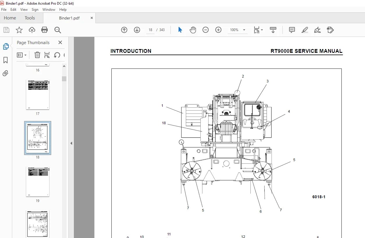
- This Manual provides information for the maintenance of the Model RT9000E Series Grove Crane.
The lift capacities are listed on the Load Chart in the cab. - The crane incorporates an all welded parallel box construction steel frame, using planetary
drive axles to provide four-wheel drive. Axle steering is accomplished utilizing hydraulic steer
cylinders. The engine is mounted at the rear of the crane carrier and provides motive power through
a six speed forward and a three speed reverse transmission. Hydraulic, double box, and sliding beam
outriggers are removable. - The carrier frame incorporates an integral fifth wheel, to which the rear axle is mounted, to
provide axle oscillation. Axle oscillation lockout is automatic when the superstructure rotates
from the travel position. - The superstructure is capable of 360 degree rotation in either direction. All crane functions are
controlled from the fully-enclosed cab mounted on the superstructure. The crane is equipped with a
five-section, full power, sequenced and synchronized boom. Additional reach is obtained by
utilizing an optional swingaway boom extension. Lifting is
provided by a main hoist and an optional auxiliary hoist.
TABLE OF CONTENTS:
Grove Crane RT9000E Service Manual 077-00 – PDF DOWNLOAD
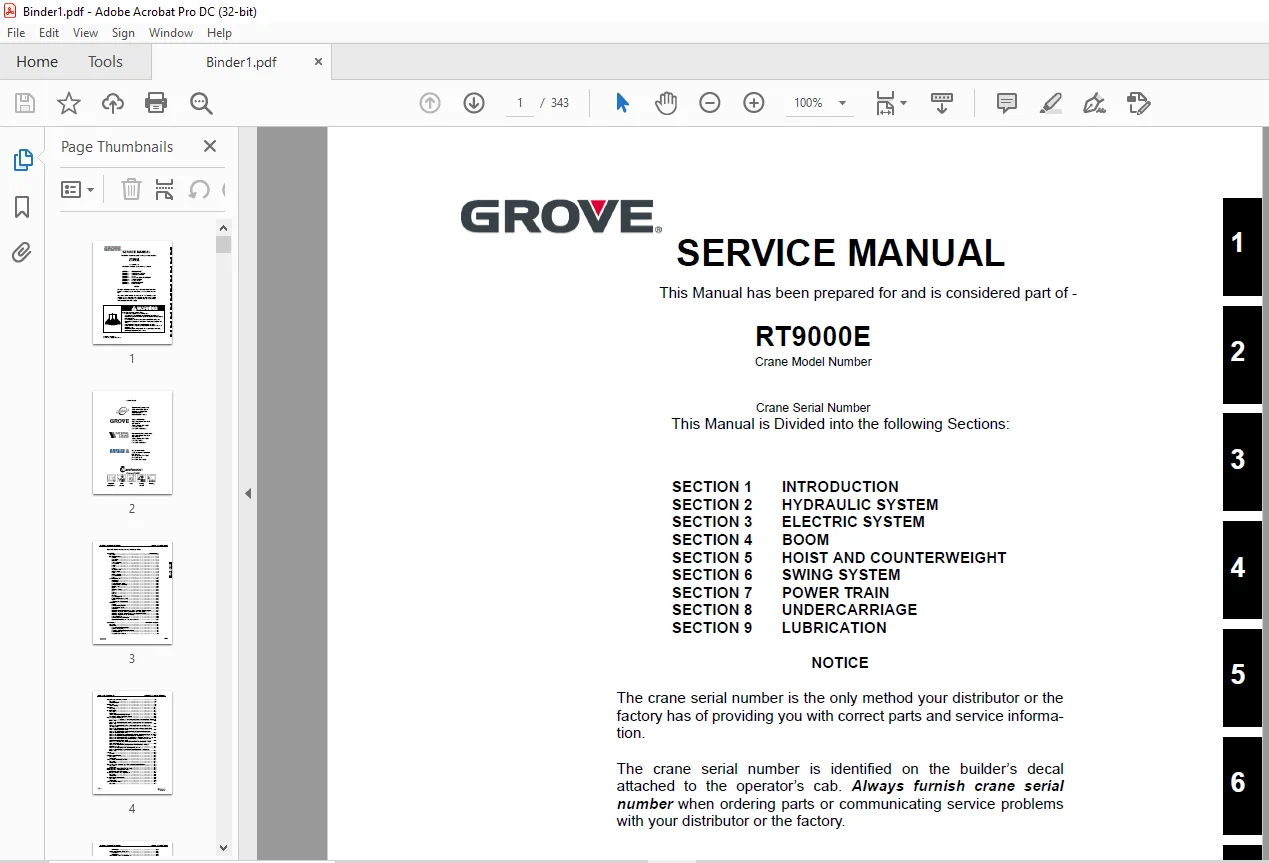
SECTION 1 INTRODUCTION
SECTION 2 HYDRAULIC SYSTEM
SECTION 3 ELECTRIC SYSTEM
SECTION 4 BOOM
SECTION 5 HOIST AND COUNTERWEIGHT
SECTION 6 SWING SYSTEM
SECTION 7 POWER TRAIN
SECTION 8 UNDERCARRIAGE
SECTION 9 LUBRICATION
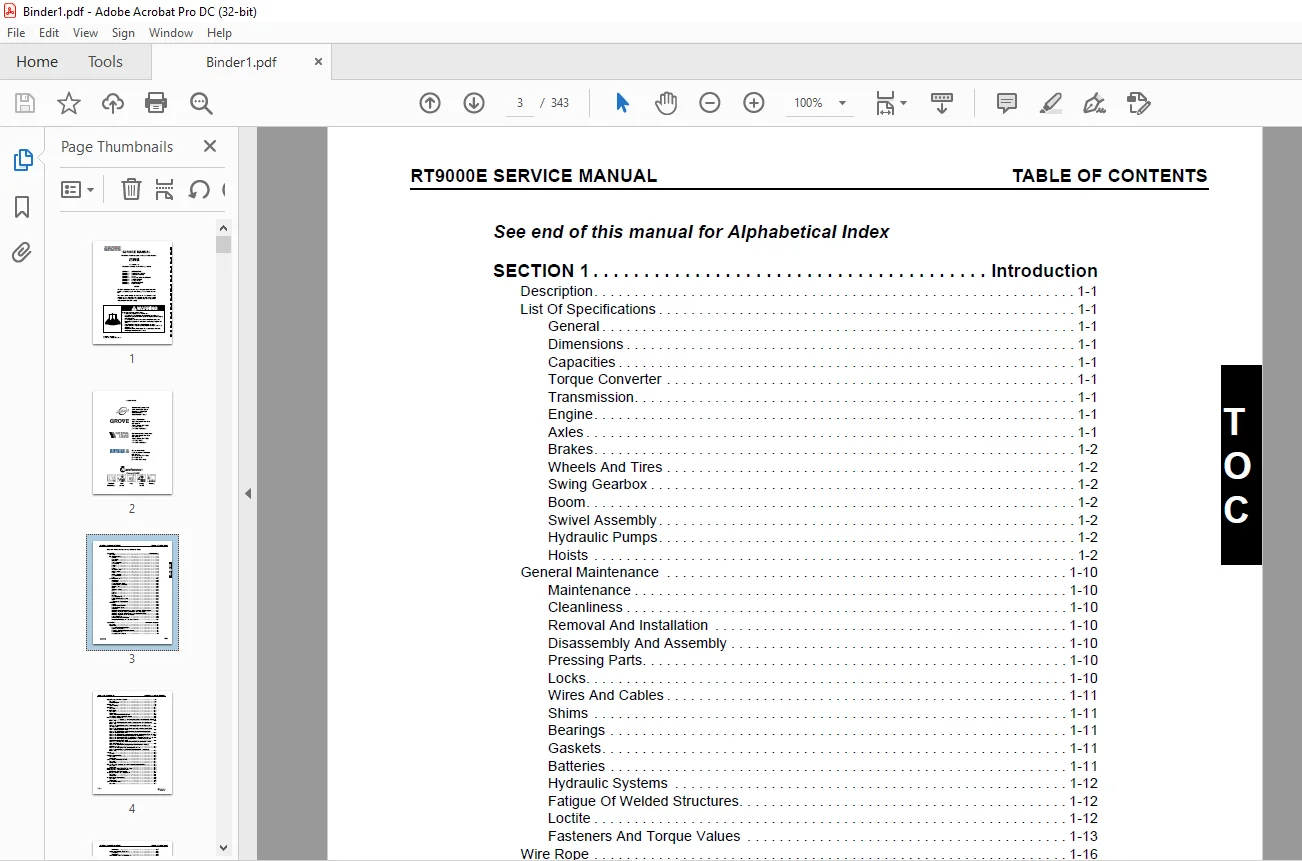
SECTION 1 Introduction
Description 1-1
List Of Specifications 1-1
General 1-1
Dimensions 1-1
Capacities 1-1
Torque Converter 1-1
Transmission 1-1
Engine 1-1
Axles 1-1
Brakes 1-2
Wheels And Tires 1-2
Swing Gearbox 1-2
Boom 1-2
Swivel Assembly 1-2
Hydraulic Pumps 1-2
Hoists 1-2
General Maintenance 1-10
Maintenance 1-10
Cleanliness 1-10
Removal And Installation 1-10
Disassembly And Assembly 1-10
Pressing Parts 1-10
Locks 1-10
Wires And Cables 1-11
Shims 1-11
Bearings 1-11
Gaskets 1-11
Batteries 1-11
Hydraulic Systems 1-12
Fatigue Of Welded Structures 1-12
Loctite 1-12
Fasteners And Torque Values 1-13
Wire Rope 1-16
General 1-16
Environmental Conditions 1-16
Dynamic Shock Loads 1-16
Lubrication 1-17
Precautions And Recommendations During Inspection Or Replacement 1-17
Wire Rope Inspection (Running Ropes And Pendant Cables) 1-18
Wire Rope Inspection (Boom Extension And Retraction Cables) 1-18
Wire Rope Replacement (All Wire Rope) 1-19
Seizing Wire Rope 1-19
Installing FLEX-X 35 Wire Rope 1-20
Procedures for Cutting and Preparing FLEX-X 35 1-21
SECTION 2 Hydraulic System
Description 2-1
Maintenance 2-1
Hydraulic Oil Recommendations 2-1
Draining and Flushing 2-1
Removing Air from the Hydraulic System 2-4
Parts Replacement 2-5
Directional Control Valves 2-5
TABLE OF CONTENTS RT9000E SERVICE MANUAL
TOC-2
Supply Pressure And Return Circuit 2-6
Description 2-6
Pump Distribution 2-7
Maintenance 2-8
Troubleshooting 2-8
Oil Cooler 2-11
Description 2-11
Hydraulic Pumps 2-12
Description 2-12
Maintenance 2-12
Testing after Rebuild or Replacement 2-13
Hydraulic Gear Pump Start-up Procedure 2-13
Pressure Setting Procedures 2-15
Procedure A – For Setting Main Directional Control Valve Reliefs see
(Figure 2-7) 2-16
Procedure B – For Checking Pressure Reducing/Sequence Valve Setting (see
(Figure 2-8) 2-18
Procedure C – For Checking Swing Brake Supply Pressure see (Figure 2-8)
and (Figure 2-9) 2-18
Procedure D – For Checking Service Brake and Air Conditioning Circuit Relief
Valve Pressure see (Figure 2-10) 2-19
Procedure E – For Checking Service Brake Dual Accumulator Charge Valve
Pressure Limits see (Figure 2-11) 2-20
Procedure F – For Checking Accumulator Pre-Charge Pressure see (Figure 2-12)2-20
Procedure G – For Pre-Charging Accumulator see (Figure 2-12) 2-21
Procedure H – For Checking Front Steer Relief Valve Pressure see (Figure 2-13) 2-21
Procedure I – For Checking Swing/Steer Directional Control Valve Work Port
Relief Pressure see (Figure 2-13) 2-21
Procedure J – For Checking Relief Setting for Counterweight Supply Control
Valve (see (Figure 2-14) 2-22
Procedure K – For Checking Outrigger/Rear Steer Relief Valve Pressure
(see (Figure 2-15) 2-23
Procedure L – For Setting Hoist Motor Control Valve see 2-23
Procedure M – For Checking Oil Cooler Circuit Relief Valve Pressure see
(Figure 2-16) 2-23
Valves 2-25
General 2-25
Directional Control Valves 2-28
Description 2-28
Maintenance 2-28
Swing Series Parallel Selector Valve 2-31
Description 2-31
Maintenance 2-31
Pressure Reducing Sequence Valve With Solenoid Controls Manifold 2-32
Description 2-32
Maintenance 2-32
Function Check – Swing Brake Release Valve 2-32
Function Check – Crane Function Valve 2-32
Inlet Filter Screen Replacement 2-32
Steering Control Valve-Dual Displacement 2-34
Description 2-34
Maintenance 2-34
Hydraulic Remote Control Valve 2-35
Description 2-35
Maintenance 2-35
Swing Power Brake Valve 2-37
Description 2-37
TOC-3
RT9000E SERVICE MANUAL TABLE OF CONTENTS
T
OC
Maintenance 2-37
Double Pilot Operated Check Valve 2-38
Description 2-38
Maintenance 2-38
Tandem Brake Valve w/ Treadle Pedal 2-39
Description 2-39
Maintenance 2-39
Dual Accumulator Charge Valve 2-40
Description 2-40
Maintenance 2-40
Hydraulic Accumulator Service Brake 2-41
Description 2-41
Maintenance 2-41
Hydraulic Accumulator Load Sense 2-42
Description 2-42
Maintenance 2-42
Holding Valves 2-43
Description 2-43
Maintenance 2-43
Shuttle Valve 2-45
Description 2-45
Maintenance 2-45
Installation 2-45
Solenoid Valves 2-46
Description 2-46
Maintenance 2-46
Cross Axle Differential Lock Valve 2-49
Description 2-49
Maintenance 2-49
Check Valves 2-50
Description 2-50
Maintenance 2-50
Outrigger/Rear Steer/Outrigger Box Pin Removal Valve 2-52
Description 2-52
Maintenance 2-52
Outrigger Control Manifold 2-54
Description 2-54
Maintenance 2-54
Pilot Operated Check Valve 2-55
Description 2-55
Maintenance 2-55
Pressure Bleed-Off Valve 2-56
Description 2-56
Maintenance 2-56
Axle Oscillation Lockout Valve 2-57
Description 2-57
Maintenance 2-57
Installation 2-57
Relief Valve 2-58
Description 2-58
Maintenance 2-58
Cylinders 2-59
General 2-59
Maintenance 2-59
Surface Protection For Cylinder Rods 2-59
Lift Cylinder 2-61
Description 2-61
TABLE OF CONTENTS RT9000E SERVICE MANUAL
TOC-4
Maintenance 2-61
Dual Rod Telescope Cylinder 2-64
Description 2-64
Maintenance 2-64
Upper Telescope Cylinder 2-68
Description 2-68
Maintenance 2-69
Axle Oscillation Lockout Cylinder 2-71
Description 2-71
Maintenance 2-71
Steer Cylinder 2-74
Description 2-74
Maintenance 2-74
Outrigger Extension Cylinder 2-77
Description 2-77
Maintenance 2-77
Outrigger Stabilizer Cylinder 2-80
Description 2-80
Maintenance 2-80
Park Brake Cylinder 2-83
Description 2-83
SECTION 3 Electrical System
Description 3-1
General 3-1
Alternator 3-1
Batteries 3-1
Relay Panel And Fuse Panel 3-1
Relays 3-2
Maintenance 3-4
General 3-4
General Troubleshooting 3-4
Troubleshooting Engine Starting Problems 3-4
Troubleshooting Engine Charging Problems 3-5
Troubleshooting Accessories 3-5
Troubleshooting Swivel-Caused Electrical Problems 3-5
Connector Troubleshooting 3-5
Troubleshooting Lights 3-8
Troubleshooting Gauges and Meters 3-8
Troubleshooting Alarms, Indicators, and Emergency Components 3-9
Troubleshooting Crane Components and Accessories 3-10
Control Module Diagnostic Light 3-10
Alternator Replacement 3-11
Starter Replacement 3-12
Battery Replacement 3-12
Relay Panel Component Replacement 3-12
Instrument Replacement 3-13
Switch Replacement 3-13
Windshield Wiper Assembly Replacement 3-14
Windshield Washer Assembly Replacement 3-15
Skylight Wiper Assembly Replacement 3-16
SECTION 4 Boom
Description 4-1
Lattice Extension 4-1
Optional Lattice Extension 4-1
TOC-5
RT9000E SERVICE MANUAL TABLE OF CONTENTS
T
OC
Optional Lattice Extension Inserts 4-1
Boom Control Switches 4-1
Theory Of Operation 4-1
Boom Extension 4-1
Boom Retraction 4-2
LMI System (With Boom Control System) 4-2
General 4-2
Telescoping Control System Description 4-2
Extension Sequence For The Main Boom (Figure 4-1) 4-3
Extension Sequence For The Main Boom With Boom Extensions Or Offset Jibs 4-3
Electronic Control System 4-5
Maintenance 4-6
Removal 4-6
Boom Disassembly 4-7
Boom Nose Sheaves 4-14
Boom Assembly 4-15
Installation 4-19
Functional Check 4-20
Inspection 4-20
Boom Alignment And Servicing 4-20
Cam Operated Check Valve Adjustment 4-20
Guide Block Adjustment 4-21
Boom Extension And Retraction Cable 4-21
Maintenance 4-21
Telescope Circuit 4-23
Description 4-23
Theory Of Operation 4-23
Maintenance 4-23
Hose Reel 4-26
Description 4-26
Maintenance 4-26
Lift Circuit 4-28
Description 4-28
Theory Of Operation 4-28
Maintenance 4-28
Boom Removal System 4-35
Description 4-35
Maintenance 4-35
Bi-Fold Swingaway Boom Extension 4-37
Description 4-37
Maintenance 4-37
Connecting and Disconnecting the Hydraulic Boom Extension 4-43
Swingaway Mounting Adjustment 4-44
Boom Extension (With Inserts) 4-45
Identification 4-45
Slinging Points 4-45
Assembly of Boom Extensions 4-45
Checklists For Rigging Work 4-46
Description of Rigging Work 4-49
Installing/Removing Two-Stage Swingaway Lattice Extension for Boom Extension4-50
Hydraulic Connection On the Boom Extension (If Unit Is Equipped With
Hydraulic Luffing Boom Extension) 4-51
Electrical Connection On the Boom Extension 4-51
Folding Out/In the Deflection Sheaves On the 8 m Sections 4-52
Positioning/Removing the Hoist Cable 4-53
Hook Block 4-54
Description 4-54
TABLE OF CONTENTS RT9000E SERVICE MANUAL
TOC-6
Maintenance 4-54
SECTION 5 Hoist And Counterweight
Description 5-1
Theory Of Operation 5-1
Maintenance 5-1
Removal 5-1
Installation 5-3
Functional Check 5-3
Servicing 5-3
Hoist To Boom Alignment 5-4
Preparation 5-4
Tools Required 5-4
Procedure 5-4
Piston Motor and Control Valve 5-6
Description 5-6
Maintenance 5-6
Idler Drum And Cable Follower 5-7
Description 5-7
Maintenance 5-7
Hoist Drum Rotation Indicator System 5-10
Description 5-10
Maintenance 5-10
Counterweight Removal 5-13
Standard Counterweight And Auxiliary Hoist Mounting Structure (Figure 5-5) 5-13
Heavy Counterweight Assembly And Auxiliary Hoist Mounting Structure
(Figure 5-5) 5-16
SECTION 6 Swing System
Description 6-1
Theory Of Operation 6-1
Swing Drive 6-1
Swing Brake 6-1
Maintenance 6-3
Troubleshooting 6-3
Swing Motor 6-7
Description 6-7
Maintenance 6-7
Swing Gearbox And Brake 6-8
Description 6-8
Maintenance 6-8
Swing Bearing 6-10
Description 6-10
Maintenance 6-10
Swivels 6-15
Description 6-15
Hydraulic Swivel 6-18
Two-Port Water Swivel 6-19
Electrical Swivel 6-20
Section 7 Power Train
Description 7-1
Maintenance 7-1
Engine Removal 7-1
Engine Installation 7-3
Engine Drive Belts 7-4
TOC-7
RT9000E SERVICE MANUAL TABLE OF CONTENTS
T
OC
Electronic Control System 7-6
Engine Control System Switches And Indicator Lights 7-6
Fuel System 7-7
Description 7-7
Maintenance 7-7
Air Intake And Exhaust System 7-10
Description 7-10
Maintenance 7-10
Water Cooling System 7-15
Description 7-15
Maintenance 7-15
Drive Train 7-21
Description 7-21
Maintenance 7-21
Torque Converter 7-22
Description 7-22
Theory Of Operation 7-22
Maintenance 7-23
Transmission 7-28
Description 7-28
Maintenance 7-28
SECTION 8 Undercarriage
Description 8-1
Maintenance 8-1
Removal 8-1
Cleaning 8-2
Installation 8-2
Wheel Alignment Check Procedure 8-2
Rear Wheels Not Centered Switch Adjustment Procedure 8-2
Wheels And Tires 8-4
Description 8-4
Maintenance 8-4
Steering Systems 8-5
Description 8-5
Theory Of Operation 8-5
Maintenance 8-5
Hydraulic Pumps 8-8
Front Steering Control Valve 8-8
Integrated Outrigger/rear Steer Control Valve 8-8
Steer Cylinders 8-9
Rear Axle Oscillation Lockout System 8-9
Axle Oscillation Lockout Cylinders 8-11
Axle Oscillation Lockout Valve 8-12
Brake System 8-13
Description 8-13
Theory Of Operation 8-13
Maintenance 8-14
Service Brakes 8-15
Parking Brake Actuator 8-21
Parking Brake 8-21
Park Brake Solenoid Valve 8-23
Outrigger Circuit 8-24
Description 8-24
Theory Of Operation 8-24
Maintenance 8-24
TABLE OF CONTENTS RT9000E SERVICE MANUAL
TOC-8
SECTION 9 Lubrication
general 9-1
Arctic Conditions Below -18°C (0°F) 9-1
lubrication points 9-1
Surface Protection for Cylinder Rods 9-1
Wire Rope Lubrication 9-10
Questions? Email us: [email protected]
PLEASE NOTE:
- This is the SAME manual used by the dealers to troubleshoot any faults in your vehicle. This can be yours in 2 minutes after the payment is made.
- Contact us at [email protected] should you have any queries before your purchase or that you need any other service / repair / parts operators manual.
S.V