Grove Crane TM 890 Superstrcture Operator`s & Safety Handbook Manual
$26.95
The Grove Crane TM 890 Superstructure Operator’s & Safety Handbook Manual is a vital guide, furnishing essential instructions for the safe and efficient operation of the TM 890 crane’s superstructure. Conveniently available as a downloadable PDF for user reference.
Description
Grove Crane TM 890 Superstrcture Operator`s & Safety Handbook Manual – PDF DOWNLOAD
FILE DETAILS:
Grove Crane TM 890 Superstrcture Operator`s & Safety Handbook Manual – PDF DOWNLOAD
Language : English
Pages : 214
Downloadable : Yes
File Type : PDF
IMAGES PREVIEW OF THE MANUAL:
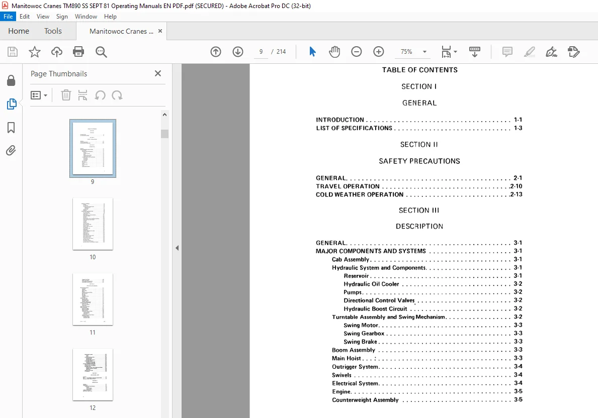
TABLE OF CONTENTS:
Grove Crane TM 890 Superstrcture Operator`s & Safety Handbook Manual – PDF DOWNLOAD
INTRODUCTION 1-1
UST OF SPECIFICATIONS 1-3
SECTION II
SAFETY PRECAUTIONS
GENERAL 2·1
TRAVEL OPERATION 2-10
COLD WEATHER OPERATION 2-13
SECTION Ill
DESCRIPTION
GENERAL 3·1
MAJOR COMPONENTS AND SYSTEMS 3-1
Cab Assembly 3-1
Hydraulic System and Components 3-1
Reservoir 3-1
Hydraulic Oil Cooter 3-2
Pumps 3-2
Directional Control Valves 3-2
Hydraulic Boost Circuit 3-2
Turntable Assembly and Swing Mechanism 3-2
Swing Motor ; 3-3
Swing Gearbox 3-3
Swing Brake 3-3
Boom Assembly 3-3
Main Hoist : 3-3
Outrigger System 3-4
Swivels 3-4
Electrical System 3-4
Engine 3-5
Counterweight Assembly 3-5
ix
OPTIONAL EQUIPMENT 3-5
Spotlight 3-5
Air Conditioner 3-5
Auxiliary Hoist Controlled Free-Fall 3-5
Operating Control 3-7
Hoist Brakes 3 7
Auxiliary Hoist 3-8
Lattice Jib 3-8
CAB CONTROLS ANO tNDICA TORS 3-8
Foot Throttle Pedal 3-8
Throttle Lock Control 3-8
Ignition Switch · 3-11
Engine Stop Control (Detroit Diesel Only) 3-11
Heater Control Switch 3-11
X
Fuel Tank 3-11
Defroster Fan 3-11
Engine Emergency Stop Control {Detroit Diesel Only) 3-12
Engine Quick Start System {Optiona0 3-12
Fuel Gauge 3-12
Voltmeter 3-12
Tachometer 3-12
Oil Pressure Gauge 3-13
Water Temperature Gauge 3-13
Ignition On Light 3-13
Hydraulic Pump Drive Control 3-13
Cab Domelight 3-13
Control Console Light 3-13
lights Switch 3-13
Windshield Wiper 3-14
Hydraulic Oil Bypassing Filter(s) Light 3-14
Swing Horn Button 3-14
Swing Control 3·14
Swing Brake Pedal 3-14
Swing Brake Switch 3-15
Positive Swing Lock Control Handle 3-15
Boom Telescope Controls 3-15
Boom Elevation Control 3-15
Auxiliary Hoist Control (Optional) 3-16
Main Hoist Control 3-16
Hoist Rotation Indicator 3· 16
Free-Fall Control Lever (Optional) 3-16
Main and Auxiliary Hoists Speed Selector Switches 3-16
Outrigger Control Panels 3-16
Bubble Level Indicator 3-17
Counterweight Positioning Control , 3-17
Counterweight Removal Controls 3-17
SECTION IV
OPERATING PROCEDURES
PRE-STARTING CHECKS 4-1
Fuel Supply , 4·1
Engine Oil 4-1
Engine Coolant 4-1
Batteries 4-1
Hydraulic Oil Reservoir and Fitter 4-1
Daily lubrication 4-1
Wire Rope 4-2
Hook Block 4-2
Swingaway Extension 4-2
Air Cleaner 4-2
ENGINE OPERATION 4-2
Starting Procedure 4-3
Cold Weather Starting 4-4
Shutdown Procedure 4-5
Emergency Engine Shutdown 4 5
GENERAL CRANE OPERATION 4-6
Handling the Load 4-6
Control Lever Operation 4-7
Pretoad Check 4-8
USING YOUR LOAD CHART 4-9
CRANE FUNCTIONS 4-11
Setting the Outriggers 4-11
Stowing the Outriggers 4-13
Swinging the Boom 4-15
Elevating and Lowering the Boom 4-16
Elevating the Boom 4-16
Lowering the Boom 4-16
Foot Control 4-17
Emergency Boom Operating Procedures 4-17
Telescoping the Boom 4-18
Extending the Boom 4-18
Retracting the Boom 4-19
CHANGE 1 · 9/22/81 xi I
Power–Pinned Fly Section 4-19
ExtellCI :4-19
Retract: ” ” 4-21
LOWM’ing and Railing the Cable 4-22
Low illg the Cab-le ~-4, 23
Raili119 the- Cable 4-23
Hoist Speed R11111 Selection 4-23
Counterweight OP1f8t , 4-24
ExtellCling the Counterweight 4-24
Retracting the Counterweight 4-24
OPTIONAL EQUIPMENT OPERATION 4-25
Setting the Center Front Stabilizer 4-26
Stowing the Center Front Stabilizer 4-26
Controlecl Fr f 111 4-27
0,, ating the Hoist in the Controll«I frN-f all Mode 4-27
Suggested Procedures for 0peraton 4-28
Bac:lc Preaure -4–29
Engine Quick Start System 4-29
Air COIIClitioMr 4-29
SECTION V
OPERATIONAL AIDS
GENERAL “” 5-1
PAT LOAD MOMENT INDICATING ILMO SYSTEM 5-1
CONTROL LEVER LOCKOUT CIRCUIT 5-1
SECTION Vt
LUBRICATION
GENERAL 6-1
LUBRICANTS 6-1
Hydraulic Oil Recommendations 6-4
VilCOlity 6-4
Arctic Conditions 6-6
Antiwear Additives 6-6
LUBRICATION POINTS 6-6
WIRE ROPE LUBRICATION 6-14
xii
SECTION VII
SET-UP AND INSTALLATION PROCECURES
GENERAL 7-1
INSTALLING CABLE ON HOIST DRUM 7-1
CABLE REEVING 7-2
Repositioning the Inner Idler Sheave 7-4
Single Part Reeving 7-4
Over the Main Boom Nose With the Auxiliary
Boom Nose (Rooster Sheave) 7-4
Over the Main Boom Nose Without the Auxiliary
Boom Nose (Rooster Sheave) 7-7
Multi-Part Reeving 7-9
ERECTING AND STOWING THE 32-FOOT (9 75 M)
SWINGAWAY EXTENSION 7-9
Erecting 7 -9
Stowing 7-14
ERECTING AND STOWING THE MULTI-SECTION LATTICE
JIB AND MAST 7-16
Erecting the 46-Foot (14 0 m) Jib 7-16
Stowing the 46-Foot (14 0 m) Jib 7-22
Swinging the Boom 7-26
Elevating and Lowering the Boom 7-27
Elevating the Boom 7-27
lowering the Boom 7-27
Erecting the 60, 74, and/or 88-Foot (18 3, 22 6,
and/or 26 8 ml Jibs 7-28
Stowing the 60, 74, and/or 88-Foot (18 3, 22 6,
and/or 26 8 m) Jibs 7-29
REMOVING AND INSTALLING THE COUNTERWEIGHT 7-29
Removal 7-29
Installation 7-34
TRAILING BOOM SET-UP 7-361
Operating Mode to the Trailing Mode 7-36
Trailing Mode to the Operating Mode 7-40
CHANGE
Questions? Email us: [email protected]
S.M