Grove Crane TM800E Operators Manual – PDF DOWNLOAD
$28.95
Grove Crane TM800E Operators Manual – PDF DOWNLOAD
Description
Grove Crane TM800E Operators Manual – PDF DOWNLOAD
FILE DETAILS:
Grove Crane TM800E Operators Manual – PDF DOWNLOAD
Language : English
Pages :154
Downloadable : Yes
File Type : PDF
TABLE OF CONTENTS:
Grove Crane TM800E Operators Manual – PDF DOWNLOAD
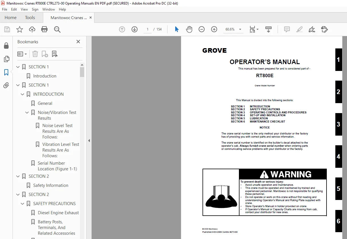
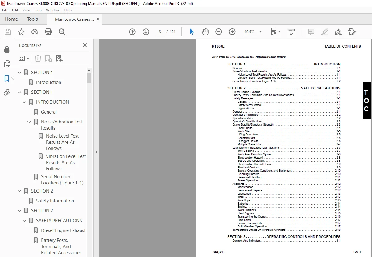
SECTION 1 9
Introduction 9
SECTION 1 11
INTRODUCTION 11
General 11
Noise/Vibration Test Results 11
Noise Level Test Results Are As Follows: 11
Vibration Level Test Results Are As Follows: 11
Serial Number Location (Figure 1-1) 12
SECTION 2 17
Safety Information 17
SECTION 2 19
SAFETY PRECAUTIONS 19
Diesel Engine Exhaust 19
Battery Posts, Terminals, And Related Accessories 19
Safety Messages 19
General 19
Safety Alert Symbol 19
Signal Words 19
General 19
Operator’s Information 20
Operational Aids 20
Operator’s Qualifications 21
Crane Stability/Structural Strength 21
Load Charts 22
Work Site 23
Lifting Operations 23
Counterweight 24
Outrigger Lift Off 24
Multiple Crane Lifts 25
Load Moment indicating (LMI) Systems 25
Two-Blocking 25
Work Area Definition System 26
Electrocution Hazard 26
Set-Up and Operation 26
Electrocution Hazard Devices 27
Electrical Contact 27
Special Operating Conditions and Equipment 28
Crushing Hazards 28
Personnel Handling 29
Travel Operation 30
Accidents 30
Maintenance 30
Service and Repairs 30
Lubrication 31
Tires 31
Wire Rope 31
Batteries 32
Engine 32
Work Practices 32
Hand Signals 34
Transporting the Crane 34
Shut-Down 35
Boom Extension/Jib 35
Cold Weather Operation 35
Temperature Effects On Hydraulic Cylinders 36
SECTION 3 37
Operating Controls and Procedures 37
SECTION 3 41
OPERATING CONTROLS AND PROCEDURES 41
Controls And Indicators 41
Defroster Switch 41
Hand Throttle Control 41
Ignition Switch 41
Voltmeter 41
Transmission Oil Temperature Gauge 41
Heat Control Knob 41
Fan Control Switch 46
Park Brake Control Switch 46
Air Conditioner Control Switch 46
Swing Brake Control Switch 46
Axle Differential Lock Control Switch (Optional) 46
2-Speed Swing Switch 46
Drive Axle Selector Switch 46
Cab Tilt Switch 46
Outrigger Control Switches 47
Work Light Switch 47
Headlights Switch 47
Boom Lights Switch (Optional) 47
Hazard Lights Switch 47
Hose Reel Brake On Indicator 47
Fuel Gauge 47
Engine Diagnostics Switches 47
Engine Coolant Temperature Gauge 47
Tachometer 47
Crane Function Power Switch 47
Outriggers Extend/Retract Switch 48
Load Moment Indicating (LMI) and Work Area Definition System Control Panel 48
Auto/Manual Boom Telescope Mode Switch 48
Center Mid/Inner Mid Boom Telescope Section Select Switch 48
Rear Steer Control Switch 48
Auxiliary Hoist Speed Selector Switch (Optional) 48
Swing Control Lever 48
Turn Signal Lever and Windshield Wiper/ Washer Controls 49
Bubble Level Indicator 49
Cab Circulating Fan 49
Electrical System Diagnostic Indicator 49
Swing Brake Pedal 49
Telescope Control Foot Pedal 49
Windshield Wiper 49
Defroster Fan 49
Service Brake Pedal 49
Spotlight (Optional) 49
Foot Throttle Pedal 49
Transmission Shift Lever 49
Turntable Lock Control (Pin Type) 50
Hoist Rotation Indicators 50
Main Hoist Control Lever 50
360 Degree Swing Lock Control (Positive Lock Type) 50
Main Hoist Speed Selector Switch 50
-29° C Indicator (Optional) 50
Luffing Jib Raise/Lower Switch (Optional) 50
Luffing Jib On/Off Switch (Optional) 50
Seat Switch (Not Shown) 50
Cab Dome Light 50
Fire Extinguisher 51
Boom Lift Control Lever 51
12 VDC Accessory Outlet 51
Auxiliary Hoist Control Lever 51
Horn 51
Right Turn Signal Indicator 51
Left Turn Signal Indicator 51
Rear Wheels Not Centered Indicator 51
Hoist 3rd Wrap Indicator (Optional w/CE) 51
Engine Stop Indicator 51
Engine Warning Indicator 51
Engine Service Indicator 51
Wait To Start Indicator 51
Low Brake Pressure Indicator 51
Transmission Service Indicator (XMSN) 51
Water In Fuel Indicator 52
Boom Not Sync Indicator 52
Throttle Mode Switch 52
Hourmeter (Not Shown) 52
Skylight Wiper (Not Shown) 52
Backup Alarm (Not Shown) 52
Armrest Switch (Not Shown) 52
Boom Telescope Mode A/B Select Switch 52
Low Steer Pressure Indicator (CE Option) 52
Boom Lift/Main Hoist Controller (Dual Axis Option) 52
Telescope/Auxiliary Hoist/Swing Controller (Dual Axis Option) 53
Operating Procedures 54
Pre-Starting Checks 54
Cold Weather Operation 54
Battery Disconnect Switch 55
Crane Travel Operation 56
General Crane Operation 61
Crane Travel Operation 66
Stowing and Parking 67
SECTION 4 69
SET-UP AND INSTALLATION 69
SECTION 4 71
SET-UP AND INSTALLATION 71
General 71
Installing Cable On The Hoist 71
Cable Reeving 71
Dead-End Rigging/Wedge Sockets 72
Installing Wedge and Socket 72
Counterweight and Auxiliary Hoist 77
Counterweight Without Auxiliary Hoist 77
Installing the Bi-Fold Manual Boom Extension 80
Checking the Transport Condition 82
Boom Extension Erecting and Stowing Procedure 82
General Warnings 82
Preparing the Crane for Boom Extension Erection Procedure 82
Erecting Procedure 83
Stowing Procedure, Boom Extensions 90
Reeve the hoist cable as described in this section 95
Hose Drum for Hydraulic Luffing Boom Extension 96
Raising and Lowering the Hydraulic Boom Extension 97
Transportation on a Separate Vehicle 98
Connecting and Disconnecting the Hydraulic Boom Extension 98
Hydraulic Connection at the Boom Extension100
Lifting Limit Switch on the Lattice Extension101
Folding Out/In the Deflection Sheaves on the 33 ft (101 m) Section102
Positioning/Remove the Hoist Cable103
Setting the Folding Swingaway Extension Offset (Figure 4-79)104
Removing the Bi-Fold Manual Boom Extension105
Installing/Removing 16 ft (49 m) Sections105
Installing the 16 ft (49 m) Sections106
Removing the 16 ft (49 m) Sections106
Boom Extension (Additional Equipment)106
Identification and Slinging Points106
Assembly Of Boom Extensions (Figure 4-82)107
Electrical Connection at the Boom Extension107
Unfolding/Folding the Deflection Sheave on the 16 ft (49 m) Section108
Positioning/Removing the Hoist Cable109
Traveling with Hydraulic Luffing or Manually Offsettable Boom Extension and/or Inserts Erected110
Adjustment Procedure for Stowage Brackets for Hydraulic Luffing Jib110
Auxiliary Single-Sheave Boom Nose (Additional Equipment)111
Identification111
Installing/Removing Auxiliary Single-Sheave Boom Nose111
Removing the Auxiliary Single-Sheave Boom Nose112
Rigging The Auxiliary Single-Sheave Boom Nose112
Rigging in Transport Position112
Rigging in Working Position113
Attaching and Removing Hoist Cable114
Possible Reeving Methods on the Auxiliary Single-Sheave Boom Nose114
Lifting Limit Switch114
Raising And Setting Down The Main Boom With Rigged Lattice Extension115
Telescoping With Rigged Lattice Extension115
Operating With The Lattice Extension115
Procedure if the Permissible Wind Speed is Exceeded116
Monthly Maintenance Work116
SECTION 5119
Lubrication119
SECTION 5121
LUBRICATION121
General121
Lubrication Intervals121
Arctic Conditions – Below -18°C (0°F)121
Arctic Conditions Down To -40°F121
Surface Protection for Cylinder Rods122
Wire Rope Lubrication122
Lubrication Points122
CraneLUBE123
Safety123
Steering and Suspension124
Axles126
Drive Train128
Drive Train (continued)130
Turntable132
Cab Tilt134
Outriggers136
Boom138
Boom (continued)140
Boom (continued)142
Hoist144
Hydraulic146
SECTION 6149
Maintenance Checklist149
SECTION 6151
MAINTENANCE CHECKLIST151
General151
Instructions151
Daily or 10 Hour Check List151
IMAGES PREVIEW OF THE MANUAL:
S.M 08/24