Grove Crane TMS 700E Operator’s Manual – PDF DOWNLOAD
$24.95
Grove Crane TMS 700E Operator’s Manual – PDF DOWNLOAD
Description
Grove Crane TMS 700E Operator’s Manual – PDF DOWNLOAD
FILE DETAILS:
Grove Crane TMS 700E Operator’s Manual – PDF DOWNLOAD
Language : English
Pages : 118
Downloadable : Yes
File Type : PDF
IMAGES PREVIEW OF THE MANUAL:
DESCRIPTION:
Grove Crane TMS 700E Operator’s Manual – PDF DOWNLOAD
INTRODUCTION:
GENERAL:
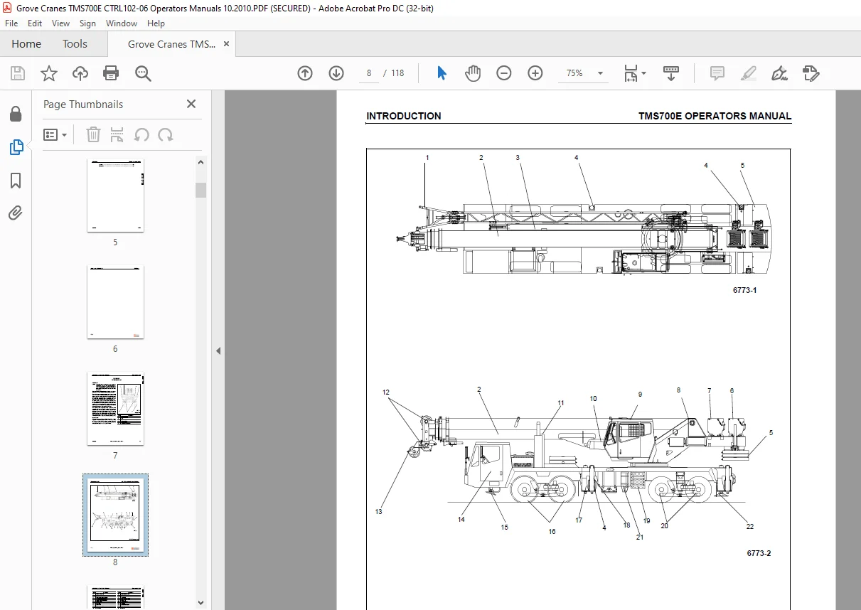
This Handbook provides important information for the operator of the TMS700E Series Grove Manitowoc Crane. The mobile crane carrier incorporates an all welded steel frame. The 8x4x4 carrier utilizes two drive axles and two steer axles. Axle steering is provided by a power steering pump, gearbox and control valve.
- The engine is mounted in the front of the carrier and provides power through an 11 speed forward and 3 speed reverse manual transmission. Hydraulic, single stage double box telescopic beams with inverted stabilizer (jack) cylinder outriggers are integral with the carrier frame.
- The outriggers are utilized in three position; fully extended, intermediate (50%) extended, and fully retracted. The carrier is also equipped with a center front stabilizer that has a permanently stowed pad.
- The superstructure is capable of 360° rotation in either direction. All crane functions, with the exception of counterweight removal, are controlled from the fullyenclosed cab mounted on the superstructure.
- The crane is equipped with a four-section boom. Additional reach is obtained by utilizing an optional swingaway boom extension. Lifting is provided by a main hoist and an optional auxiliary hoist.
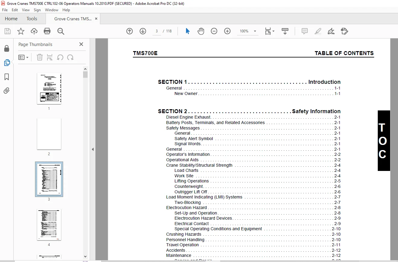
TABLE OF CONTENTS:
Grove Crane TMS 700E Operator’s Manual – PDF DOWNLOAD
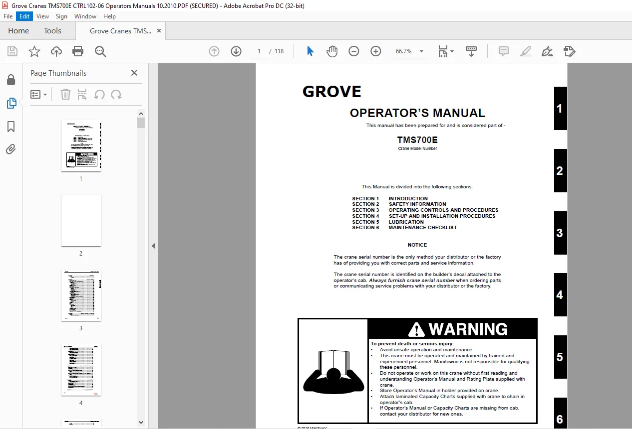
SECTION 1 INTRODUCTION
SECTION 2 SAFETY INFORMATION
SECTION 3 OPERATING CONTROLS AND PROCEDURES
SECTION 4 SET-UP AND INSTALLATION PROCEDURES
SECTION 5 LUBRICATION
SECTION 6 MAINTENANCE CHECKLIST
SECTION 1 Introduction
General 1-1
New Owner 1-1
SECTION 2 Safety Information
Diesel Engine Exhaust 2-1
Battery Posts, Terminals, and Related Accessories 2-1
Safety Messages 2-1
General 2-1
Safety Alert Symbol 2-1
Signal Words 2-1
General 2-1
Operator’s Information 2-2
Operational Aids 2-2
Crane Stability/Structural Strength 2-4
Load Charts 2-4
Work Site 2-4
Lifting Operations 2-5
Counterweight 2-6
Outrigger Lift Off 2-6
Load Moment Indicating (LMI) Systems 2-7
Two-Blocking 2-7
Electrocution Hazard 2-8
Set-Up and Operation 2-8
Electrocution Hazard Devices 2-9
Electrical Contact 2-9
Special Operating Conditions and Equipment 2-10
Crushing Hazards 2-10
Personnel Handling 2-10
Travel Operation 2-11
Accidents 2-12
Maintenance 2-12
Service and Repair 2-12
Lubrication 2-12
Wire Rope 2-13
Batteries 2-14
Engine 2-14
Work Practices 2-14
Crane Access 2-14
Job Preparation 2-14
Working 2-15
Lifting 2-15
Hand Signals 2-16
Transporting The Crane 2-17
Boom Extension/Jib 2-17
Cold Weather Operation 2-17
Temperature Effects on Hydraulic Cylinders 2-18
SECTION 3 Operating Controls and Procedures
Carrier Cab 3-1
Engine Controls and Indicators 3-1
TABLE OF CONTENTS TMS700E
TOC-2
Travel Controls and Indicators 3-2
Craning Controls and Indicators 3-6
Accessory Controls and Indicators 3-7
Additional Optional Carrier Controls and Indicators 3-8
Superstructure Cab 3-10
Engine Controls and Indicators 3-10
Crane Controls and Indicators 3-12
Accessory Controls and Indicators 3-16
Operating Procedures 3-17
Breaking In A New Carrier 3-17
Pre-Starting Checks 3-17
Cold Weather Operation 3-18
Engine Operation 3-18
General Crane Operation 3-20
Using Your Load Chart 3-20
Crane Functions 3-21
Operational Aids 3-25
Crane Travel Operation 3-26
Stowing and Parking 3-33
Crane Shutdown Procedures 3-33
Unattended Crane 3-34
SECTION 4 Set-up And Installation Procedures
General 4-1
Installing Cable On The Hoist 4-1
Cable Reeving 4-1
Dead-End Rigging/Wedge Sockets 4-6
Installing Wedge and Socket 4-6
Erecting and Stowing the Bi-Fold Boom Extension 4-8
Erecting 4-8
Stowing 4-15
Setting The Folding Swingaway Offset 4-16
Erecting and Stowing the Bi-Fold Boom Extension Using the 6 1 m (20 foot) Insert 4-17
Erecting 4-17
Stowing 4-17
Removable Counterweight 4-19
Mounting The Counterweight 4-19
Stowing The Counterweight 4-19
SECTION 5 Lubrication
General 5-1
Arctic Conditions Below -18°C (0°F) 5-1
ALL Weather Package & Lubricants 5-1
Standard Lubricants Package 5-2
Lubrication Points 5-2
Carrier Lubrication 5-4
HYDRAULIC Lubrication 5-8
Superstructure Lubrication 5-9
Boom, Boom Extension, and Boom Accessories Lubrication 5-10
Wire Rope Lubrication 5-12
SECTION 6 Maintenance Checklist
General 6-1
Instructions 6-1
Need help? Contact: [email protected]
https://vimeo.com/852078904?share=copy
PLEASE NOTE:
- This is the SAME exact manual used by your dealers to fix your vehicle.
- The same can be yours in the next 2-3 mins as you will be directed to the download page immediately after paying for the manual.
- Any queries / doubts regarding your purchase, please feel free to contact [email protected]
S.V