Grove Crane TMS800E Service Manual 108-00 – PDF DOWNLOAD
$28.95
Grove Crane TMS800E Service Manual 108-00 – PDF DOWNLOAD
Description
Grove Crane TMS800E Service Manual 108-00 – PDF DOWNLOAD
FILE DETAILS:
Grove Crane TMS800E Service Manual 108-00 – PDF DOWNLOAD
Language : English
Pages : 364
Downloadable : Yes
File Type : PDF
IMAGES PREVIEW OF THE MANUAL:
DESCRIPTION:
Grove Crane TMS800E Service Manual 108-00 – PDF DOWNLOAD
INTRODUCTION:
Description:
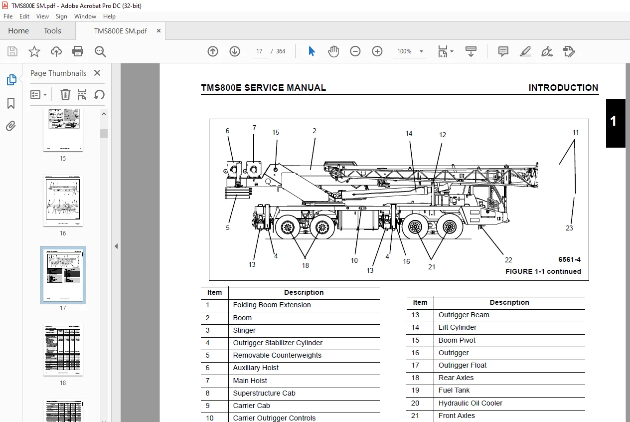
- This Manual provides information for the maintenance of the Model TMS800E Series Grove Crane (see Figure 1-1).
- The lift capacities are listed on the Load Chart in the superstructure cab.
- The carrier incorporates a high strength, low alloy steel, all welded triple box section steel
frame. The 8x4x4 carrier utilizes two drive axles and two steer axles. Axle steering is power
assist controlled and controlled by the steering wheel. The engine is mounted at the front of the
crane carrier and provides motive power through an 10 speed forward and 2 speed reverse manual
transmission. - The outriggers are two stage, double box, telescopic beam type outriggers. The outriggers have
three positions; fully extended, intermediate (50%) extended, and fully retracted.
The superstructure is capable of 360 degree rotation in either direction. All crane functi ons,
with except ion of counterweight removal, are controlled from the fully enclosed cab
mounted on the superstructure. - One boom is available on the crane; a four section, full power, Mega Form, 12.6 to 39 meter (41 to
128 foot) boom. Additional reach is obtained by utilizing a 10 to 17 meter (33 to 56 foot) bi-fold
boom extension. A 6.1 meter (20 foot) and a 12.2 meter (40 foot) lattice insert is also a ailable
for use between the boom nose and the swingaway.
TABLE OF CONTENTS:
Grove Crane TMS800E Service Manual 108-00 – PDF DOWNLOAD
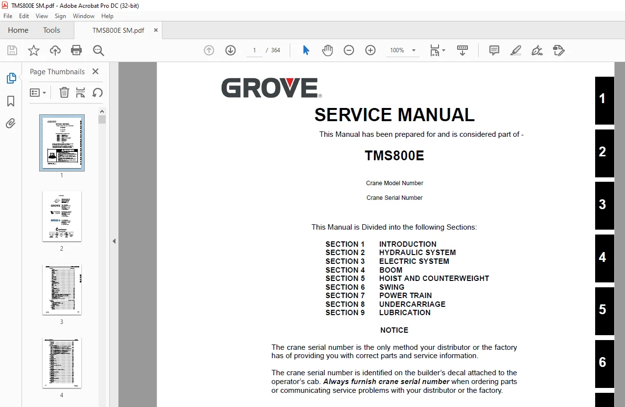
SECTION 1 INTRODUCTION
SECTION 2 HYDRAULIC SYSTEM
SECTION 3 ELECTRIC SYSTEM
SECTION 4 BOOM
SECTION 5 HOIST AND COUNTERWEIGHT
SECTION 6 SWING
SECTION 7 POWER TRAIN
SECTION 8 UNDERCARRIAGE
SECTION 9 LUBRICATION
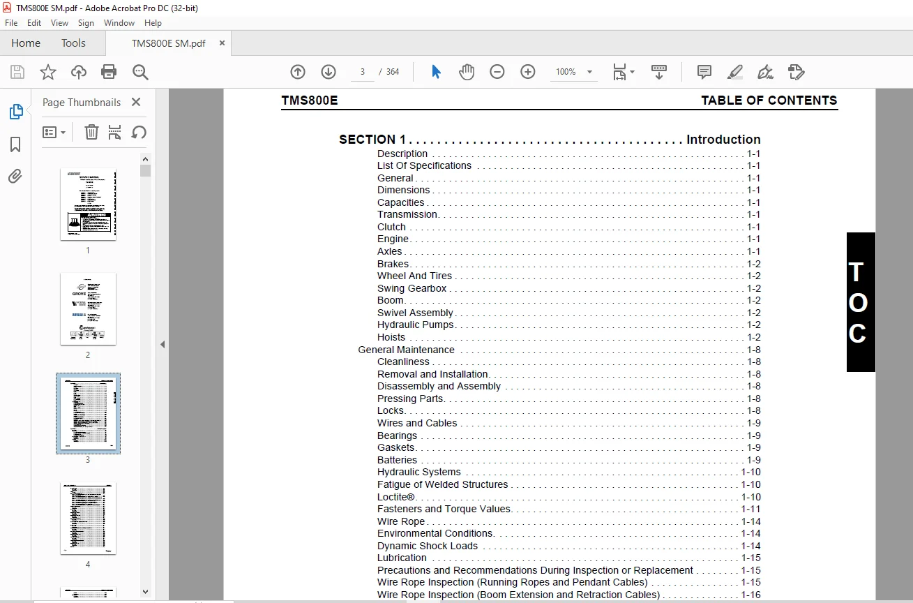
SECTION 1 Introduction
Description 1-1
List Of Specifications 1-1
General 1-1
Dimensions 1-1
Capacities 1-1
Transmission 1-1
Clutch 1-1
Engine 1-1
Axles 1-1
Brakes 1-2
Wheel And Tires 1-2
Swing Gearbox 1-2
Boom 1-2
Swivel Assembly 1-2
Hydraulic Pumps 1-2
Hoists 1-2
General Maintenance 1-8
Cleanliness 1-8
Removal and Installation 1-8
Disassembly and Assembly 1-8
Pressing Parts 1-8
Locks 1-8
Wires and Cables 1-9
Bearings 1-9
Gaskets 1-9
Batteries 1-9
Hydraulic Systems 1-10
Fatigue of Welded Structures 1-10
Loctite® 1-10
Fasteners and Torque Values 1-11
Wire Rope 1-14
Environmental Conditions 1-14
Dynamic Shock Loads 1-14
Lubrication 1-15
Precautions and Recommendations During Inspection or Replacement 1-15
Wire Rope Inspection (Running Ropes and Pendant Cables) 1-15
Wire Rope Inspection (Boom Extension and Retraction Cables) 1-16
Wire Rope Replacement (All Wire Rope) 1-16
Seizing Wire Rope 1-17
Installing FLEX-X 35 Wire Rope 1-18
Procedures for Cutting and Preparing FLEX-X 35 1-18
SECTION 2 Hydraulic System
Description 2-1
Maintenance 2-1
Hydraulic Oil Recommendations 2-1
Removing Air From The Hydraulic System 2-4
Parts Replacement 2-5
Directional Control Valves 2-5
Supply Pressure And Return Circuit 2-6
Description 2-6
Maintenance 2-9
Oil Cooler 2-12
Description 2-12
Maintenance 2-12
TABLE OF CONTENTS TMS800E
TOC-2
Hydraulic Pumps 2-14
Description 2-14
Maintenance 2-14
Valves 2-18
General 2-18
Pressure Setting Procedures 2-20
Procedure A – For Checking/Setting The Main Directional Control Valve For
Hoist(s) And Boom Lift 2-21
Procedure B – For Checking/Setting The Outrigger/Swing Pressures 2-22
Procedure C – For Checking/Setting The Oil Cooler and Air Conditioner Motor
Pressure 2-22
Procedure D – For Checking/Setting The Engine Charge Air Cooler Pressure 2-22
Procedure E – For Checking/Setting The Front Steer Pressure 2-22
Procedure F – For Checking/Setting Swing Brake Release Pressure 2-22
Procedure G – For Checking/Setting The Pilot Supply Pressure 2-23
Procedure H – For Checking/Setting The Piston Pump 2-23
Procedure I – For Checking/Setting The Center Front Stabilizer Pressure 2-23
Directional Control Valves 2-29
Description 2-29
Maintenance 2-29
Check Valves 2-34
Description 2-34
Maintenance 2-34
Outrigger Selector Valve 2-35
Description 2-35
Maintenance 2-35
Outrigger Control Manifold 2-37
Description 2-37
Maintenance 2-37
Pilot Operated Check Valve 2-39
Description 2-39
Maintenance 2-39
Cab Tilt Double Pilot Operated Check Valve 2-40
Description 2-40
Maintenance 2-40
Holding Valves 2-41
Description 2-41
Maintenance 2-41
Accessory Manifold With Swing Directional Control Valve 2-42
Description 2-42
Maintenance 2-42
Front Center Stabilizer Relief Valve 2-45
Description 2-45
Maintenance 2-45
Manual Flow Control Valve 2-46
Description 2-46
Maintenance 2-46
Two Speed Swing Valve 2-47
Description 2-47
Maintenance 2-47
Charge Air Cooler Control Manifold 2-48
Description 2-48
Maintenance 2-48
Motor Control Manifold 2-49
Description 2-49
Maintenance 2-49
Cylinders 2-50
TOC-3
TMS800E TABLE OF CONTENTS
T
OC
General 2-50
Maintenance 2-50
Lift Cylinder 2-52
Description 2-52
Maintenance 2-52
Lower Telescope Cylinder 2-55
Description 2-55
Maintenance 2-55
Upper Telescope Cylinder 2-59
Description 2-59
Maintenance 2-59
Steer Cylinder 2-62
Description 2-62
Maintenance 2-62
Outrigger Extension Cylinder 2-65
Description 2-65
Maintenance 2-65
Outrigger Stabilizer Cylinder 2-69
Description 2-69
Maintenance 2-69
Center Front Stabilizer Cylinder 2-73
Description 2-73
Maintenance 2-73
Counterweight Removal Cylinder 2-77
Description 2-77
Maintenance 2-77
Cab Tilt Cylinder 2-80
Description 2-80
Maintenance 2-80
SECTION 3 Electric System
Description 3-1
General 3-1
Alternator 3-1
Batteries 3-1
Carrier Relay and Fuse Panel 3-1
Superstructure Relay and Fuse Panel 3-6
Maintenance 3-7
General 3-7
General Troubleshooting 3-7
Troubleshooting Swivel-Caused Electrical Problems 3-8
Connector Troubleshooting 3-8
Control Module Diagnostic Light 3-8
Alternator Replacement 3-9
Starter Replacement 3-9
Battery Replacement 3-10
Relay Panel Component Replacement 3-10
Instrument Replacement 3-11
Switch Replacement 3-11
Windshield Wiper Assembly Replacement 3-12
Windshield Washer Assembly Replacement 3-13
Skylight Wiper Assembly Replacement 3-14
Troubleshooting 3-14
TABLE OF CONTENTS TMS800E
TOC-4
SECTION 4 Boom
Description 4-1
Lattice Extension 4-1
Optional Lattice Extension 4-1
Theory of Operation 4-1
Boom Extension 4-1
Boom Retraction 4-1
Maintenance 4-1
Removal 4-1
Boom Disassembly 4-2
Boom Nose Sheaves 4-9
Assembly 4-10
Installation 4-13
Functional Check 4-13
Inspection 4-14
Boom Alignment And Servicing 4-14
Cam Operated Check Valve Adjustment 4-14
Stop Block Adjustment 4-14
Front Upper Pad Adjustment 4-14
Read Side Wear Pad Adjustment 4-14
Boom Extension And Retraction Cable 4-14
Maintenance 4-14
Inspection 4-15
Adjustment 4-15
Telescope Circuit 4-17
Description 4-17
Theory of Operation 4-17
Maintenance 4-17
Lift Circuit 4-20
Description 4-20
Theory of Operation 4-20
Maintenance 4-20
Auxiliary Boom Nose 4-24
Description 4-24
Installing the Bi-Fold Manual Boom Extension 4-25
Checking the Transport Condition 4-25
Boom Extension Erecting and Stowing Procedure 4-27
General Warnings 4-27
Preparing the Crane for Boom Extension Erection Procedure 4-27
Erecting Procedure 4-27
Stowing Procedure 4-32
Raising and Lowering the Hydraulic Boom Extension 4-36
Transportation on a Separate Vehicle 4-36
Lifting Limit Switch on the Lattice Extension 4-37
Folding Out/In the Deflection Sheaves on the 33 ft (10 1 m) Section 4-37
Positioning/Remove the Hoist Cable 4-38
Setting the Folding Swingaway Extension Offset Figure 4-52 4-38
Removing the Bi-Fold Manual Boom Extension 4-40
Installing/Removing 16 ft (4 9 m) Sections 4-40
Installing the 16 ft (4 9 m) Sections 4-40
Removing the 16 ft (4 9 m) Sections 4-41
Boom Extension (Additional Equipment) 4-41
Identification and Slinging Points 4-41
Assembly Of Boom Extensions Figure 4-55 4-41
Electrical Connection at the Boom Extension 4-42
Unfolding/Folding the Deflection Sheave on the 16 ft (4 9 m) Section 4-43
TOC-5
TMS800E TABLE OF CONTENTS
T
OC
Positioning/Removing the Hoist Cable 4-44
Traveling with Manually Offsettable Boom Extension and/or Inserts Erected 4-45
Auxiliary Single-Sheave Boom Nose (Additional Equipment) 4-45
Identification 4-45
Installing/Removing Auxiliary Single-Sheave Boom Nose 4-45
Removing the Auxiliary Single-Sheave Boom Nose 4-46
Rigging The Auxiliary Single-Sheave Boom Nose 4-46
Rigging in Transport Position 4-46
Rigging in Working Position 4-47
Attaching and Removing Hoist Cable 4-48
Possible Reeving Methods on the Auxiliary Single-Sheave Boom Nose 4-48
Lifting Limit Switch 4-48
Raising And Setting Down The Main Boom With Rigged Lattice Extension 4-49
Telescoping With Rigged Lattice Extension 4-49
Operating With The Lattice Extension 4-49
Procedure if the Permissible Wind Speed is Exceeded 4-49
Monthly Maintenance Work 4-50
Hookblock 4-51
Description 4-51
Maintenance 4-51
SECTION 5 Hoist and Counterweight
Description 5-1
Theory of Operation 5-1
Maintenance 5-1
Warm-up Procedure 5-1
Removal 5-1
Installation 5-1
Functional Check 5-3
Functional Check 5-3
Servicing 5-3
Hoist To Boom Alignment 5-4
Preparation 5-4
Tools Required 5-4
Procedure 5-4
Piston Motor And Control Valve 5-6
Description 5-6
Maintenance 5-6
Idler Drum and Cable Follower 5-7
Description 5-7
Maintenance 5-7
Hoist Drum Indicator System 5-10
Description 5-10
Maintenance 5-10
Hoist Control Valves 5-12
Description 5-12
Counterweight 5-13
Description 5-13
Maintenance 5-13
Mounting The Counterweight 5-13
Stowing The Counterweight 5-13
SECTION 6 Swing System
Description 6-1
Theory Of Operation 6-1
Swing Drive 6-1
TABLE OF CONTENTS TMS800E
TOC-6
Swing Brake 6-1
Maintenance 6-3
Troubleshooting 6-3
Swing Motor 6-6
Description 6-6
Maintenance 6-6
Swing Gearbox And Brake 6-7
Description 6-7
Maintenance 6-7
Swing Bearing 6-9
Description 6-9
Maintenance 6-9
Swivels 6-14
Description 6-14
Hydraulic Swivel 6-17
Description 6-17
Theory Of Operation 6-17
Maintenance 6-17
Integral W/Hydraulic Water Swivel 6-18
Description 6-18
Maintenance 6-18
Installation 6-19
Electrical Swivel 6-19
Description 6-19
Theory Of Operation 6-19
Maintenance 6-19
SECTION 7 Power Train
Description 7-1
Maintenance 7-1
Removal 7-1
Installation 7-4
Engine Drive Belts 7-4
Engine Control System 7-6
Description 7-6
Fuel System 7-8
Description 7-8
Maintenance 7-8
Air Intake System 7-10
Description 7-10
Maintenance 7-10
Water Cooling System 7-15
Description 7-15
Maintenance 7-15
Drive Train 7-22
Description 7-22
Maintenance 7-22
Clutch 7-24
Description 7-24
Theory Of Operation 7-24
Maintenance 7-25
UltraShift™ Transmission 7-31
Description 7-31
Theory Of Operation 7-31
Maintenance 7-34
TOC-7
TMS800E TABLE OF CONTENTS
T
OC
SECTION 8 UnderCarriage
Front Axle And Suspension 8-1
Description 8-1
Maintenance 8-1
Steering System 8-11
Description 8-11
Maintenance 8-11
Steering Pump 8-14
Description 8-14
Steering Gearbox 8-14
Description 8-14
Maintenance 8-14
Steer Cylinder 8-15
Description 8-15
Maintenance 8-15
Rear Axle And Suspension 8-17
Description 8-17
Maintenance 8-17
Wheels And Tires 8-21
Description 8-21
Maintenance 8-21
Brakes 8-23
Description 8-23
Maintenance 8-23
Front Brakes 8-24
Description 8-24
Rear Brakes 8-30
Description 8-30
Automatic Slack Adjuster 8-33
Description 8-33
Maintenance 8-35
Air System 8-39
Description 8-39
Theory Of Operation 8-39
Maintenance 8-39
Air System Components 8-44
Description 8-44
Maintenance 8-47
Outriggers 8-55
Description 8-55
Theory Of Operation 8-55
Maintenance 8-56
Outrigger Beam 8-59
Description 8-59
Theory Of Operation 8-59
Maintenance 8-59
Extension Cylinder 8-62
Description 8-62
Outrigger Stabilizer Cylinder 8-63
Description 8-63
Maintenance 8-63
Installation 8-63
Outrigger System Valves 8-64
Description 8-64
Center Front Stabilizer Cylinder 8-65
Description 8-65
TABLE OF CONTENTS TMS800E
TOC-8
Maintenance 8-65
SECTION 9 Lubrication
General 9-1
Arctic Conditions Below -18°C (0°F) 9-1
Lubrication Points 9-1
Surface Protection for Cylinder Rods 9-1
Carrier Lubrication 9-3
Superstructure Lubrication 9-7
Boom, Boom Extension, and Boom Accessories Lubrication 9-8
Wire Rope Lubrication 9-9
Questions? Email us: [email protected]
https://vimeo.com/888651361?share=copy
S.V