Grove JLG VM 3242E VM 2642E Service & Maintenance Manual PN 31210043 – PDF DOWNLOAD
$27.95
Grove JLG VM 3242E VM 2642E Service & Maintenance Manual PN 31210043 – PDF DOWNLOAD
Description
Grove JLG VM 3242E VM 2642E Service & Maintenance Manual PN 31210043 – PDF DOWNLOAD
FILE DETAILS:
Grove JLG VM 3242E VM 2642E Service & Maintenance Manual PN 31210043 – PDF DOWNLOAD
Language : English
Pages : 106
Downloadable : Yes
File Type : PDF
IMAGES PREVIEW OF THE MANUAL:
DESCRIPTION:
Grove JLG VM 3242E VM 2642E Service & Maintenance Manual PN 31210043 – PDF DOWNLOAD
INTRODUCTION – MAINTENANCE SAFETY PRECAUTIONS:
A.GENERAL:
This section contains the general safety precautions which must be observed during maintenance of the aerial platform. It is of utmost importance that maintenance personnel pay strict attention to these warnings and precautions to avoid possible injury to themselves or others, or damage to the equipment. A maintenance program must be followed to ensure that the machine is safe to operate.
B HYDRAULIC SYSTEM SAFETY:
- It should be noted that the machines hydraulic systems operate at extremely high, potentially dangerous pressures. Every effort should be made to relieve any system pressure prior to disconnecting or removing any portion of the system.
- Relieve system pressure by cycling the applicable control several times, to direct any line pressure back into the res- ervoir. Pressure feed lines to system components can then be disconnected with minimal fluid loss.
C MAINTENANCE:
• REMOVE ALL RINGS, WATCHES AND JEWELRY WHEN PERFORMING ANY MAINTENANCE.
• DO NOT WEAR LONG HAIR UNRESTRAINED, OR LOOSE-FITTING CLOTHING AND NECKTIES WHICH
ARE APT TO BECOME CAUGHT ON OR ENTANGLED IN EQUIPMENT.
• OBSERVE AND OBEY ALL WARNINGS AND CAUTIONS ON MACHINE AND IN SERVICE MANUAL.
• KEEP OIL, GREASE, WATER, ETC. WIPED FROM STANDING SURFACES AND HAND HOLDS.
• NEVER WORK UNDER AN ELEVATED STRUCTURE UNTIL STRUCTURE HAS BEEN SAFELY RESTRAINED FROM ANY MOVEMENT BY BLOCKING OR OVERHEAD SLING.
• BEFORE MAKING ADJUSTMENTS, LUBRICATING OR PERFORMING ANY OTHER MAINTENANCE, SHUT
OFF ALL POWER CONTROLS.
• BATTERY SHOULD ALWAYS BE DISCONNECTEDDURING REPLACEMENT OF ELECTRICAL COMPONENTS.
• KEEP ALL SUPPORT EQUIPMENT AND ATTACHMENTS STOWED IN THEIR PROPER PLACE.
• USE ONLY APPROVED, NONFLAMMABLE CLEANING SOLVENTS.
TABLE OF CONTENTS:
Grove JLG VM 3242E VM 2642E Service & Maintenance Manual PN 31210043 – PDF DOWNLOAD
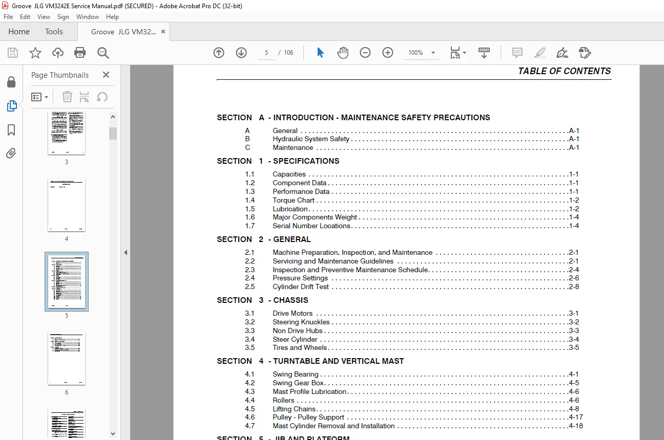
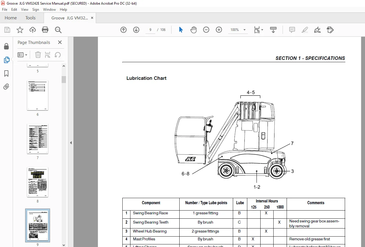
Section A. INTRODUCTION - MAINTENANCE SAFETY PRECAUTIONS......  3
	A General.................................................  3
	B Hydraulic System Safety.................................  3
	C Maintenance.............................................  3
Section 1. SPECIFICATIONS.....................................  7
	1.1 Capacities............................................  7
		Hydraulic Oil Tank - Main.............................  7
		Hydraulic System......................................  7
		Hydraulic Oil Tank - Steering Unit....................  7
		Hydraulic System - Steering...........................  7
	1.2 Component Data........................................  7
		Battery - Battery Charger.............................  7
		Main Hydraulic Pump / Electric Motor Assembly.........  7
		Steering Hydraulic Pump / Electric Motor Assembly.....  7
	1.3 Performance Data......................................  7
		Travel speed (Forward and Reverse)....................  7
		Gradeability..........................................  7
		Turning Radius........................................  7
		Mast Speed............................................  7
		Jib Speed.............................................  7
		Turntable Swing Speed (Left and Right)................  7
		Machine Weight........................................  7
		Ground Bearing pressure...............................  7
		Machine Height (Stowed)...............................  7
		Machine Length (Stowed)...............................  7
		Machine Width.........................................  7
		Wheel base............................................  7
		Up and Over Platform Height...........................  7
		Horizontal Reach Up and Over..........................  7
		Max. Platform Height..................................  7
	1.4 Torque Chart..........................................  8
	1.5 Lubrication...........................................  8
		General...............................................  8
		Recommended hydraulic oil.............................  8
		Lubrication Chart.....................................  9
		Lube Specifications...................................  9
	1.6 Major Components Weight............................... 10
	1.7 Serial Number Locations............................... 10
Section 2. general............................................ 11
	2.1 Machine Preparation, Inspection, and Maintenance...... 11
		General............................................... 11
	2.2 Servicing and Maintenance Guidelines.................. 11
		General............................................... 11
		Safety and Workmanship................................ 11
		Cleanliness........................................... 11
		Components Removal and Installation................... 11
		Component Disassembly and Reassembly.................. 11
		Bearings.............................................. 11
		Care and Installation of Teflon Coated Bushings....... 12
		Bolt Usage and Torque Application..................... 12
		Hydraulic Lines and Electrical Wiring................. 12
		Hydraulic System...................................... 12
		Welding on Work Platform.............................. 13
		Lubrication........................................... 13
		Lubrication and Servicing............................. 13
	2.3 Inspection and Preventive Maintenance Schedule........ 14
		Performances Codes :.................................. 16
	2.4 Pressure Settings..................................... 17
		Main Relief [PR1]..................................... 17
		Swing Right [PR2]..................................... 17
		Swing left [PR3]...................................... 17
		Mast Up [PR4]......................................... 17
		Jib Up [PR5].......................................... 17
		Jib Down [PR6]........................................ 17
		Brake Release [PR7]................................... 18
		Drive Torque [PR8].................................... 18
	2.5 Cylinder Drift Test................................... 18
Section 3. CHASSIS............................................ 21
	3.1 Drive Motors.......................................... 21
		Drive motor removal................................... 21
		Drive Motor Installation.............................. 21
	3.2 Steering Knuckles..................................... 22
		Steering Knuckle Removal.............................. 22
		Cleaning and Inspection............................... 22
		Steering Knuckle Installation......................... 22
	3.3 Non Drive Hubs........................................ 23
		Hub Disassembly....................................... 23
		Cleaning and Inspection............................... 23
		Hub Assembly.......................................... 23
		Non Drive Hub Lubrication............................. 23
	3.4 Steer Cylinder........................................ 24
		Steer Cylinder Removal and Installation............... 24
	3.5 Tires and Wheels...................................... 25
		Tires characteristics................................. 25
Section 4. TURNTABLE AND VERTICAL MAST........................ 27
	4.1 Swing Bearing......................................... 27
		Swing bearing Mounting Bolts Check.................... 27
		Swing Bearing Lubrication............................. 27
		Internal Gear Lubrication............................. 27
		Replacement of Swing Bearing.......................... 28
	4.2 Swing Gear Box........................................ 31
		Swing gear box removal................................ 31
		Swing Gear Box Disassembly............................ 31
		Swing Gear Box Assembly............................... 31
		Gear Box Installation................................. 31
	4.3 Mast Profile Lubrication.............................. 32
	4.4 Rollers............................................... 32
		Inspection............................................ 32
		Removal and Installation.............................. 32
		Mast transversal play / Mast sections alignment....... 33
	4.5 Lifting Chains........................................ 34
		Safety Accessories and Tooling........................ 34
		Lubrication........................................... 34
		Lifting Chains Inspection............................. 35
		Lifting Chains Removal and Installation............... 36
		Lifting Chain Tension Adjustment...................... 42
	4.6 Pulley - Pulley Support............................... 43
		Pulley Inspection..................................... 43
		Removal and Installation.............................. 44
	4.7 Mast Cylinder Removal and Installation................ 44
		Mast Cylinder Removal................................. 44
		Mast cylinder installation............................ 45
Section 5. JIB AND PLATFORM................................... 47
	5.1 Jib Cylinder Removal and Installation................. 47
		Jib Cylinder Removal.................................. 47
		Jib Cylinder Installation............................. 48
Section 6. HYDRAULICS......................................... 49
	6.1 Main Hydraulic Oil Tank............................... 49
	6.2 Steering Unit......................................... 50
	6.3 Hydraulic Filters..................................... 51
		Return filter......................................... 51
		Cartridge replacement :............................... 51
		Pressure Filter....................................... 51
		Cartridge replacement................................. 51
	6.4 Hydraulic Pump / Electric Motor Assembly.............. 52
		Motor Ventilation Holes Cleaning...................... 52
		Brushes Length Checking (Qty 4)....................... 52
		Brushes Removal....................................... 52
		Brushes Installation.................................. 52
	6.5 Hand Pump............................................. 52
	6.6 Functions Manifold.................................... 53
	6.7 Motor Supply Manifold................................. 55
	6.8 Differential Locking Manifold......................... 56
	6.9 Brake Manifold........................................ 57
	6.10 Drive Motors......................................... 59
	6.11 Accumulator.......................................... 62
	6.12 "Free wheel" Valve................................... 62
	6.13 Swing Motor.......................................... 63
	6.14 Cylinders............................................ 63
		Cylinder Repair....................................... 64
Section 7. BATTERY / CHARGER.................................. 69
	7.1 Battery............................................... 69
		Electrolyte level..................................... 69
		Battery Cells Filling................................. 69
		Battery Cleaning...................................... 69
		Container Draining.................................... 69
		Container Maintenance................................. 70
		Centralized Filling System Maintenance................ 70
		Battery Voltage and Electrolyte Gravity............... 70
	7.2 Battery Discharge Controller Terminals................ 75
	7.3 Charger............................................... 75
Section 8. electric - control system.......................... 77
	8.1 Sensors............................................... 77
		Mast Position Switch [SW22]........................... 77
		Mast Position Switch [SW 2]........................... 77
		Steering sensors [SW24] [SW25]........................ 77
		Tilt Sensor........................................... 79
	8.2 Motor Speed Controller................................ 81
	8.3 Synoptical Switchboard................................ 83
	8.4 Drive Management Module............................... 84
	8.5 Circuits Protections.................................. 91
		Main Power Circuit Fuse [F1].......................... 91
		Steering Power Circuit Fuse [F2]...................... 91
		Panel Mounted Fuses [F3] & [F4]....................... 91
		Battery Filling Unit Fuse [F5]........................ 91
		Tilt Sensor Fuse [F6]................................. 91
		Fuses on Drive Management Module...................... 92
	8.6 "Clipper" Connector Installation Procedure............ 93
Section 9. schematics......................................... 95
	9.1 Electrical Power Circuit Overview..................... 95
	9.2 Harness Wiring........................................ 96
	9.3 Platform Console - Panel Mounted Components Wiring.... 99
	9.4 Ground Console - Panel Mounted Components Wiring......100
	9.5 Electrical Schematics.................................101
	9.6 Hydraulic Schematic...................................103
Need help? Contact: [email protected]
https://vimeo.com/874285461?share=copy
PLEASE NOTE:
- This is the same manual used by the DEALERSHIPS to SERVICE your vehicle.
- The manual can be all yours – Once payment is complete, you will be taken to the download page from where you can download the manual. All in 2-5 minutes time!!
- Need any other service / repair / parts manual, please feel free to contact us at heydownloadss @gmail.com . We may surprise you with a nice offer
S.V