Trusted Business
Verified & Licensed
Virus Free Files
100% Safe Downloads
Secure Payment
SSL Protected
Instant Delivery
Available Immediately
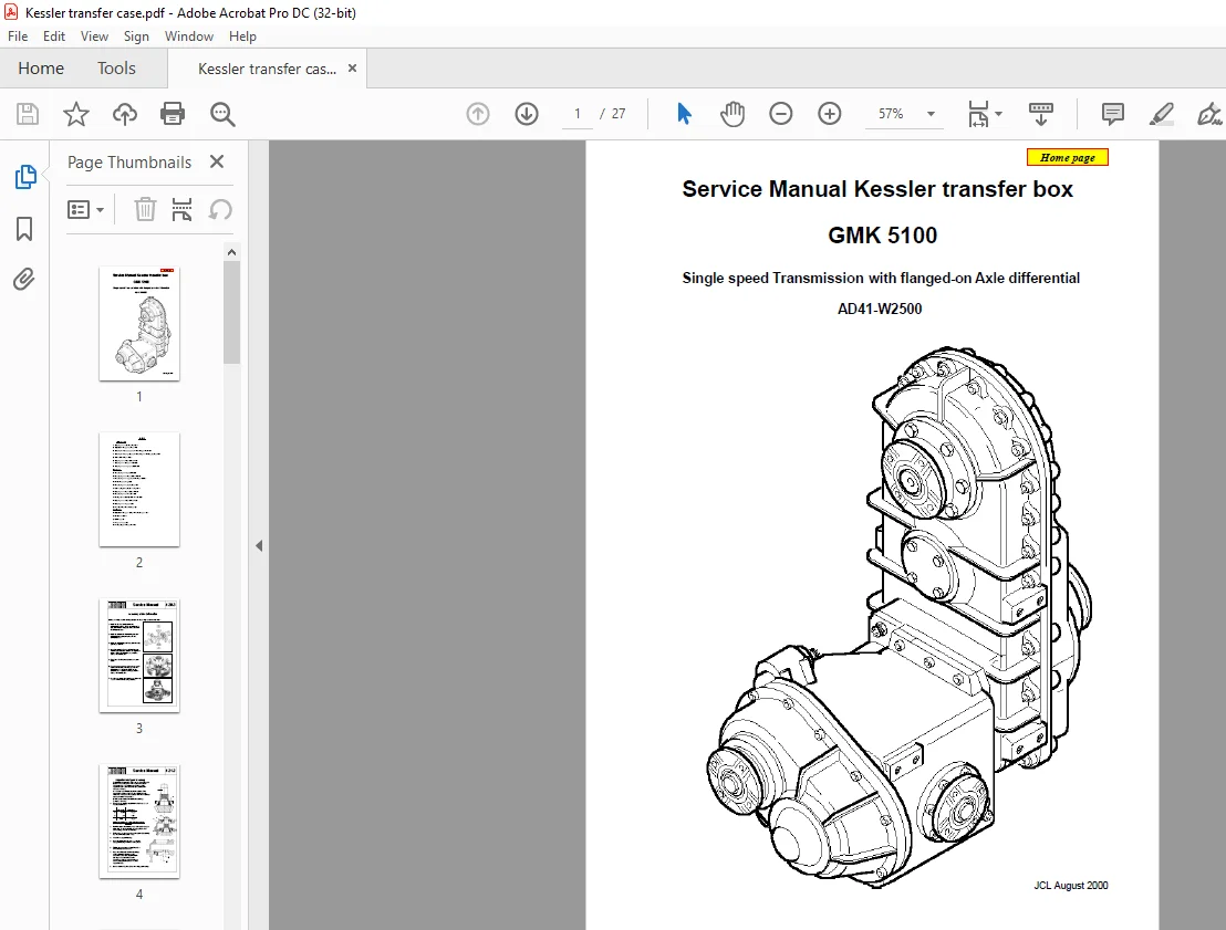
Grove Kessler transfer box GMK 5100 Service Manual AD41-W2500 – PDF DOWNLOAD
$14.95
Grove Kessler transfer box GMK 5100 Service Manual AD41-W2500 – PDF DOWNLOAD
Instant PDF Download
Available immediately
Save to Your Device
Download & keep forever
Antivirus Scanned
100% virus-free
Trusted Worldwide
175,000+ customers
Description
Grove Kessler transfer box GMK 5100 Service Manual AD41-W2500 – PDF DOWNLOAD
FILE DETAILS:
Grove Kessler transfer box GMK 5100 Service Manual AD41-W2500 – PDF DOWNLOAD
Language : English
Pages : 27
Downloadable : Yes
File Type : PDF
IMAGES PREVIEW OF THE MANUAL:
![]()
![]()
DESCRIPTION:
Grove Kessler transfer box GMK 5100 Service Manual AD41-W2500 – PDF DOWNLOAD
Assembly of the Differential:
Before assembly all of the bevel gears and the thrust rings should be well oiled .
1. Install the bearing bushings into the differential housings . Place one differential side gear
with the side gear thrust washer in the differential case .
Before assembly all of the bevel gears and the thrust rings should be well oiled .
1. Install the bearing bushings into the differential housings . Place one differential side gear
with the side gear thrust washer in the differential case .
2. Install the spider with differential gears and differential pinion thrust washers in the
differential case .
differential case .
3. Install the other differential side gear and side gear thrust washer .
4. Install the other half of the differential case over the assembly and observe the alignment
marks , tighten the differential case bolts . Secure with Loctite 262 .
marks , tighten the differential case bolts . Secure with Loctite 262 .
5. Check that all differential pinions can rotate easily .
6. Coat the contact surface of the ring gear with Loctite 270 and install the ring gear on the
differential case by tapping lightly on the circumference . Tighten the ring gear bolts . Secure
with Loctite 262 .
differential case by tapping lightly on the circumference . Tighten the ring gear bolts . Secure
with Loctite 262 .
7. Heat the two taper roller bearings to about 100
° C and install them by using a sleeve .
° C and install them by using a sleeve .
TABLE OF CONTENTS:
Grove Kessler transfer box GMK 5100 Service Manual AD41-W2500 – PDF DOWNLOAD
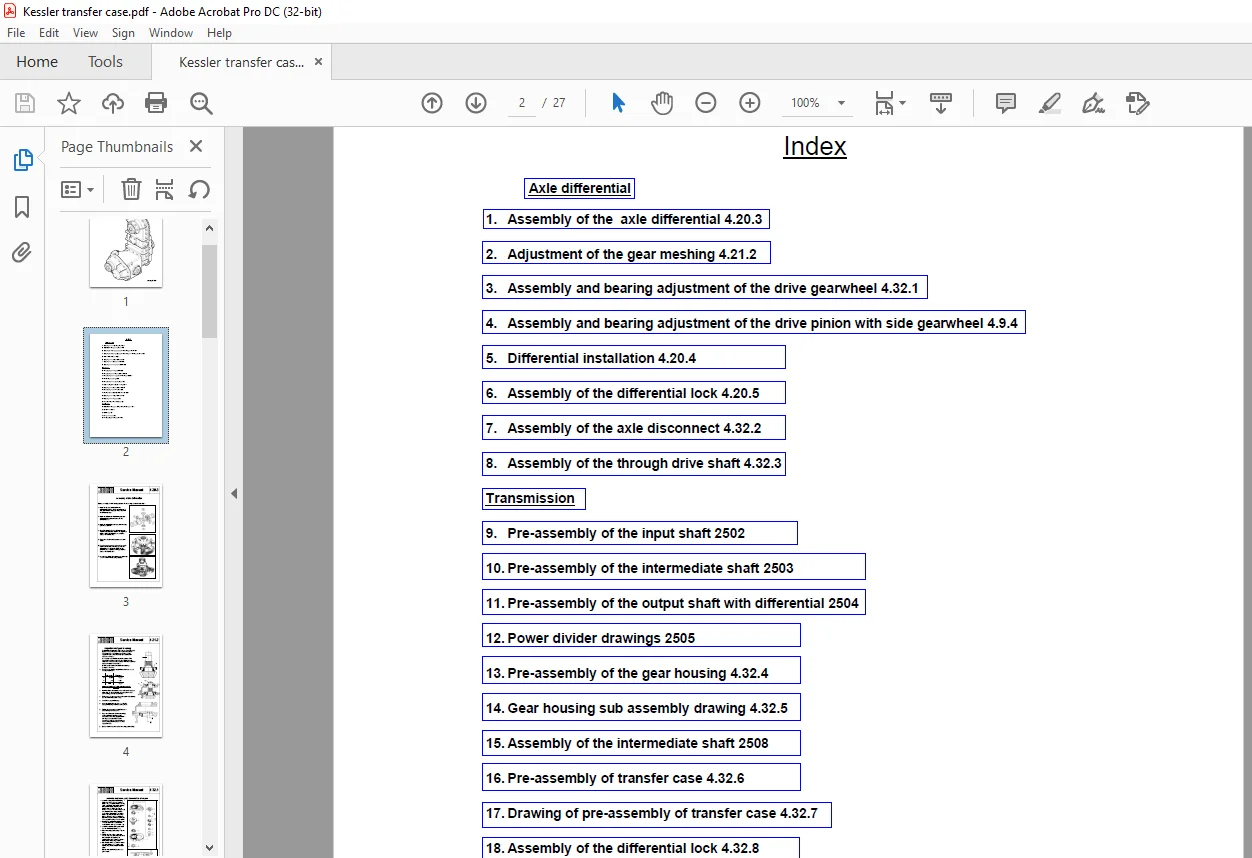
Index................................................................................ 2
Axle differential.................................................................... 3
	1.   Assembly of the Differential 4.20.3......................................... 3
	2.   Adjustment of gear meshing 4.21.2........................................... 4
	3.   Assembly and bearing adjustment of the drive gear 4.32.1.................... 5
	4.   Assembly and bearing adjustment of the drive pinion with drop gear 4.9.4.... 6
	5.   Differential installation 4.20 .4........................................... 7
	6.   Assembly of the differential lock 4.20.5.................................... 8
	7.   Assembly of the axle disconnect 4.32.2...................................... 9
	8.   Assembly of the through drive shaft 4.32.3..................................10
Transmission.........................................................................11
	9.   Pre - assembly of the input shaft 2502......................................11
	10. Pre - assembly of the intermediate shaft 2503................................12
	11. Pre - assembly of the output shaft with differential 2504....................13
	12. Power divider drawings 2505..................................................14
	13. Pre - assembly of the gear housing 4.32.4....................................15
	14. Gear housing sub assembly drawing 4.32.5.....................................16
	15. Assembly of the intermediate shaft 2508......................................17
	16. Assembly of the transfer case 4.32.6.........................................18
	17. Drawing of pre-assembly of transfer case 4.32.7..............................19
	18. Assembly of the differential lock 4.32.8.....................................20
	19. Assembly of the oil pump 4.32.9..............................................21
	20. Final assembly  of the drive assembly 4.32.10................................22
Supplements:.........................................................................23
	21. Adjustment of gear meshing of Gleason gears 4.0.1............................23
	22. Service tools 3.6.2/3........................................................24
	23. Bolt torques ( Nm ) 3.3......................................................25
	24. Flange nut torques 3.5.......................................................26
	25. Locking flange nut instructions 4.0.2........................................27
PLEASE NOTE:
- This is the SAME MANUAL used by the dealerships to diagnose your vehicle
- No waiting for couriers / posts as this is a PDF manual and you can download it within 2 minutes time once you make the payment.
- Your payment is all safe and the delivery of the manual is INSTANT – You will be taken to the DOWNLOAD PAGE.
- So have no hesitations whatsoever and write to us about any queries you may have : heydownloadss @gmail.com
S.V