Grove Manitowoc TMS9000E Crane Service Manual – PDF DOWNLOAD
Original price was: $45.95.$29.95Current price is: $29.95.
Grove Manitowoc TMS9000E Crane Service Manual – PDF DOWNLOAD
Description
Grove Manitowoc TMS9000E Crane Service Manual – PDF DOWNLOAD
DESCRIPTION:
Grove Manitowoc TMS9000E Crane Service Manual – PDF DOWNLOAD
USING THE MAINTENANCE MANUAL:
This manual is not designed to replace proper training and instruction! Truck crane maintenance personnel are required to have relevant specialised knowledge of proper safety procedures! Read sections 1 and 2 carefully before beginning maintenance work. Maintenance work on the lattice extensions is described in the operating instructions for lattice extensions.
GENERAL INSTRUCTIONS:
It is your responsibility to maintain and service the truck crane regularly in order to lengthen its service life and keep it in good working order. Please note that Manitowoc Crane Care can only uphold the warranty provided for the truck crane if the following conditions are met:
- proper use,
- prescribed care and maintenance,
- professional repair work / overhauling.
Numerous defects and failures are caused by improper maintenance such as:
- lack of oil, grease or antifreeze,
- dirt,
- rope damage,
- defective compressed air and hydraulic systems,
- hose damage or loose screw connections,
- defective brakes,
- defective tires or wheel rims,
- exceeded maintenance intervals.
For your safety and the safety of others, avoid these errors by carrying out maintenance work carefully within the specified intervals. Do not put off maintenance work that is due. Notify either your local Manitowoc Crane Care or your qualified repair personnel immediately should repair work become necessary. This work may only be carried out by trained, qualified personnel.
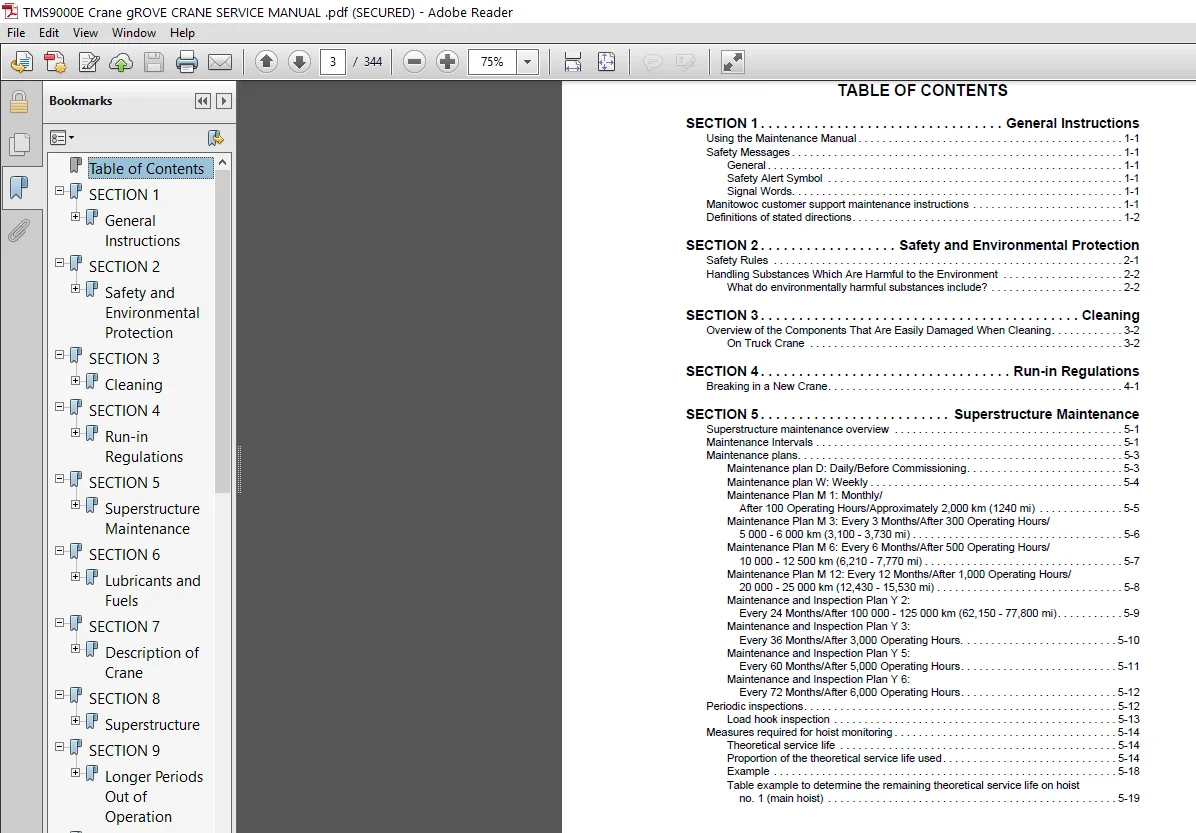
TABLE OF CONTENTS:
Grove Manitowoc TMS9000E Crane Service Manual – PDF DOWNLOAD
SECTION 1 General Instructions
Using the Maintenance Manual 1-1
Safety Messages 1-1
General 1-1
Safety Alert Symbol 1-1
Signal Words 1-1
Manitowoc customer support maintenance instructions 1-1
Definitions of stated directions 1-2
SECTION 2 Safety and Environmental Protection
Safety Rules 2-1
Handling Substances Which Are Harmful to the Environment 2-2
What do environmentally harmful substances include? 2-2
SECTION 3 Cleaning
Overview of the Components That Are Easily Damaged When Cleaning 3-2
On Truck Crane 3-2
SECTION 4 Run-in Regulations
Breaking in a New Crane 4-1
SECTION 5 Superstructure Maintenance
Superstructure maintenance overview 5-1
Maintenance Intervals 5-1
Maintenance plans 5-3
Maintenance plan D: Daily/Before Commissioning 5-3
Maintenance plan W: Weekly 5-4
Maintenance Plan M 1: Monthly/
After 100 Operating Hours/Approximately 2,000 km (1240 mi) 5-5
Maintenance Plan M 3: Every 3 Months/After 300 Operating Hours/
5 000 – 6 000 km (3,100 – 3,730 mi) 5-6
Maintenance Plan M 6: Every 6 Months/After 500 Operating Hours/
10 000 – 12 500 km (6,210 – 7,770 mi) 5-7
Maintenance Plan M 12: Every 12 Months/After 1,000 Operating Hours/
20 000 – 25 000 km (12,430 – 15,530 mi) 5-8
Maintenance and Inspection Plan Y 2:
Every 24 Months/After 100 000 – 125 000 km (62,150 – 77,800 mi) 5-9
Maintenance and Inspection Plan Y 3:
Every 36 Months/After 3,000 Operating Hours 5-10
Maintenance and Inspection Plan Y 5:
Every 60 Months/After 5,000 Operating Hours 5-11
Maintenance and Inspection Plan Y 6:
Every 72 Months/After 6,000 Operating Hours 5-12
Periodic inspections 5-12
Load hook inspection 5-13
Measures required for hoist monitoring 5-14
Theoretical service life 5-14
Proportion of the theoretical service life used 5-14
Example 5-18
Table example to determine the remaining theoretical service life on hoist
no 1 (main hoist) 5-19
TABLE OF CONTENTS TMS9000E SERVICE MANUAL
TOC-2
SECTION 6 Lubricants and Fuels
Lubricant table 6-1
Process materials 6-2
Fuel 6-2
Engine coolant and mixtures 6-2
Windscreen washing system mixtures 6-2
Fuel for crane cab heating system 6-2
SECTION 7 Description of Crane
Overview of the operating and display elements 7-1
Axle Weight Distribution Table 7-1
SECTION 8 Superstructure
Description of maintenance work on the superstructure 8-1
Hoists 8-1
Hoists – Oil Level Check 8-1
Checking for Leaks 8-2
Checking the Hoist Brake 8-2
Lubricating Hoist Gearbox 8-2
Hoists – Oil Change 8-3
Carrying Out Partial Inspection of Hoists 8-3
Carrying Out General Inspection of Hoists 8-3
Swinging gear 8-4
Swinging Gear – Oil Level Check 8-4
Checking for Leaks 8-5
Lubricating the Swing Gear Pinion and Gear Rim 8-5
Swing gear – Oil Change 8-6
Swing gear brake function check 8-7
new york house lock 8-7
Torquing Turntable Bolts 8-7
Torque Values 8-8
Hydraulic system of the superstructure 8-10
Checking for Leaks 8-10
Bleeding the lift cylinder 8-10
Prerequisites 8-10
Bleeding the Piston Rod Chamber 8-10
Bleeding the Piston Head Chamber 8-10
Bleeding the Telescoping Cylinders 8-11
Change the hydraulic oil filter 8-12
Hydraulic Oil Filter for Control Circuit 8-13
Main boom 8-14
Notes on Maintenance of the Main Boom 8-14
Lubricating the locking pins 8-15
Lubricating the Telescope Slide Faces 8-16
Check the locking system 8-17
Hoist ropes 8-17
Checking the Position of Sheaves and Rope Drums 8-17
Checking Status 8-18
Replacing the Hoist Rope 8-24
Setting the Lowering Limit Switch 8-26
Lowering Limit Switch Function Control 8-26
rated capacity limiter 8-26
Maintenance of the Slip Ring Assembly of the Cable Drum 8-26
Lubricating the Swing Angle Sensor 8-28
Central lubrication system 8-29
Hook blocks 8-29
Grove TOC-3
TMS9000E SERVICE MANUAL TABLE OF CONTENTS
T
OC
Lubrication 8-29
Superstructure air conditioning system (additional equipment) 8-29
Checking Hoses 8-29
Other maintenance work 8-29
Checking for Correct Operation of the Auxiliary Heater (Additional Equipment) 8-29
Lubricating the Piston Rod of the Lifting Cylinder 8-30
SECTION 9 Longer Periods Out of Operation
Before the truck crane is put out of operation 9-1
If the crane is out of operation for more than 12 months: 9-1
Before putting the truck crane back into operation 9-1
SECTION 10 Tightening Torques
Fasteners and Torque Values 10-1
Torque Wrenches 10-1
Torque Values 10-2
SECTION 11 Engine
DESCRIPTION 11-1
MAINTENANCE 11-2
Removal 11-2
Installation 11-5
Engine Drive Belts 11-5
ENGINE CONTROL SYSTEM 11-6
Description 11-6
Functional Operation 11-6
Engine Control System Switches and Indicator Lights 11-7
FUEL SYSTEM 11-7
Description 11-7
Maintenance 11-8
AIR INTAKE SYSTEM 11-10
Description 11-10
Maintenance 11-10
Troubleshooting 11-10
Check For Filter Restriction 11-10
Filter Element Replacement 11-10
Element Cleaning 11-11
Air Cleaner Body 11-11
Vacuator Valve 11-11
Duct Work 11-11
Exhaust System 11-13
Description 11-13
ISX System Removal 11-13
ISX System Installation 11-13
QSM System Removal 11-13
ISX System Installation 11-13
Slip Joint Exhaust Connectors 11-13
ISX Exhaust System 11-14
QSM Exhaust System 11-15
Aftertreatment Diesel Exhaust Fluid (DEF) 11-16
DEF Tank 11-16
DEF Dosing Unit Filter 11-17
Water Cooling System 11-19
Description 11-19
Maintenance 11-19
Cleaning 11-21
TABLE OF CONTENTS TMS9000E SERVICE MANUAL
TOC-4
Component Inspection 11-22
Radiator Assembly Removal and Installation 11-23
Pump/PTO Clutch Assembly (ISX Engine) 11-27
PTO Clutch Lubrication 11-27
Pump/PTO Clutch Replacement 11-27
Pump/PTO Assembly (QSM Engine) 11-29
Pump/PTO Replacement 11-29
Air Valve Replacement 11-30
SECTION 12 Drive Train
Description 12-1
Maintenance 12-1
Drive Lines 12-1
Clutch 12-3
Description 12-3
Theory Of Operation 12-3
Maintenance 12-5
Clutch Adjustment Procedure 12-11
General Maintenance 12-12
Gearshift 12-12
Description 12-12
Maintenance 12-12
Manual Transmission 12-13
Description 12-13
Theory of Operation 12-13
Maintenance 12-13
Lubrication 12-17
Preventive Maintenance 12-18
Transmission Shift Air System 12-18
Description 12-18
Theory of Operation 12-18
SECTION 13 Front Axle, Suspension, and Steering
Front Axle 13-1
Suspension 13-1
Maintenance 13-1
General 13-1
Removal 13-4
Disassembly 13-4
Assembly 13-4
Installation 13-4
Axle Alignment Procedure 13-5
Steering System 13-11
Description 13-11
Maintenance 13-11
Steering Pump 13-14
Description 13-14
Steering Gearbox 13-14
Maintenance 13-14
Steer Cylinder 13-15
Description 13-15
Maintenance 13-15
Wheels And Tires 13-16
Description 13-16
Maintenance 13-16
Grove TOC-5
TMS9000E SERVICE MANUAL TABLE OF CONTENTS
T
OC
SECTION 14 Rear Axle and Suspension
Description 14-1
Rear Axle 14-1
Suspension 14-1
Maintenance 14-1
Removal 14-4
Disassembly 14-4
Assembly 14-4
Installation 14-5
Wheels and Tires 14-5
Description 14-5
Maintenance 14-5
Mounting the Wheels on the Axle 14-5
SECTION 15 Brakes
Description 15-1
Air Supply 15-1
Normal Braking 15-1
Vehicle Parking 15-1
Anti-lock Braking Systems (ABS) 15-1
Automatic Traction Control 15-2
Emergency Braking 15-2
Maintenance 15-2
Non-Asbestos Warning 15-2
Front Brakes 15-2
Description 15-2
Maintenance 15-3
Automatic Slack Adjuster 15-8
Description 15-8
Maintenance 15-8
Rear Brakes 15-17
Description 15-17
Maintenance 15-17
Rear Brake Assembly 15-20
Anti-Lock Brake System (ABS)/Automatic Traction Control (ATC) 15-22
ABS System Description 15-22
ATC System Description 15-24
ABS Troubleshooting 15-26
Troubleshooting Diagnostic Trouble Codes: Traction Control Valves 15-35
Power Supply Tests 15-37
Troubleshooting Diagnostic Trouble Codes: J1939 Serial Communications 15-38
Miscellaneous Troubleshooting 15-40
Troubleshooting Wiring 15-41
Special Tools 15-44
Tests, Repair and Adjustment 15-44
Component Removal and Installation 15-47
SECTION 16 Air System
Description 16-1
Theory Of Operation 16-1
Braking 16-3
Maintenance 16-4
Leak Detection 16-4
Air System Operational Test 16-4
Air System Components 16-6
Description 16-6
TABLE OF CONTENTS TMS9000E SERVICE MANUAL
TOC-6
Maintenance 16-11
Dual Brake Valve 16-15
PTO Clutch Air Valve 16-16
SECTION 17 Hydraulic System
Description 17-1
Maintenance 17-3
Draining and Flushing 17-3
Removing Air from the Hydraulic System 17-4
Parts Replacement 17-5
Supply Pressure And Return Circuit 17-5
Description 17-5
Hydraulic Reservoir and Filter 17-5
Pump Distribution 17-5
Maintenance 17-7
Troubleshooting 17-7
Return Hydraulic Filter Assembly 17-8
Element Removal 17-8
Element Installation 17-8
Hydraulic Pumps 17-10
Description 17-10
Maintenance 17-10
Carrier Valves 17-13
General 17-13
Auxiliary Radiator Manifold 17-15
Description 17-15
Maintenance 17-15
Outrigger Selector Valve 17-17
Description 17-17
Maintenance 17-17
Outrigger Control Manifold 17-19
Description 17-19
Maintenance 17-19
Pilot Operated Check Valve 17-21
Description 17-21
Maintenance 17-21
Front Center Stabilizer Relief Valve 17-23
Description 17-23
Maintenance 17-23
Superstructure Valves 17-24
Turntable Hydraulic System 17-24
Crane Control 17-26
Cylinders 17-29
General 17-29
Maintenance 17-29
Steer Cylinder 17-32
Description 17-32
Maintenance 17-32
Outrigger Extension Cylinder 17-35
Description 17-35
Maintenance 17-35
Outrigger Stabilizer Cylinder 17-38
Description 17-38
Maintenance 17-38
Center Front Stabilizer Cylinder 17-42
Description 17-42
Grove TOC-7
TMS9000E SERVICE MANUAL TABLE OF CONTENTS
T
OC
Maintenance 17-42
Lift Cylinder 17-45
Description 17-45
Maintenance 17-45
Differential Cylinder 17-48
Description 17-48
Telescope Cylinder 17-49
Description 17-49
SECTION 18 Pressure Setting Procedures
OBJECTIVE 18-1
EQUIPMENT 18-1
Carrier Notes 18-2
Carrier Hydraulic Pressure Setting Procedures 18-4
A Procedure for checking/setting the outrigger/swing pressures 18-4
B Procedure for checking/setting the front steer pressure 18-4
C Procedure for checking/setting the center front stabilizer pressure 18-5
Superstructure Hydraulic System 18-6
D Procedure for checking/setting pump differential pressure 18-9
E Procedure for checking/setting pump cut-off pressure 18-11
F Procedure for checking/setting control pressure 18-12
G Procedure for checking/setting main hoist lower pressure 18-13
H Procedure for checking/setting aux hoist lower pressure 18-14
I Procedure for checking/setting tele in/out pressure 18-15
J Procedure for checking/setting tele pinning pressure 18-16
K Procedure for checking/setting lift raise pressure 18-17
L Procedure for checking/setting counterweight raise/lower pressure 18-17
M Procedure for checking/setting cab tilt raise/lower pressure 18-18
N Procedure for checking/setting luffing jib out/in pressure 18-19
O Procedure for checking/setting swing pressure 18-20
SECTION 19 Outriggers
Description 19-1
Theory Of Operation 19-1
Maintenance 19-2
Troubleshooting 19-2
Outrigger Beam (with Adjustable Wear Pads) 19-5
Extension Cylinder 19-9
Description 19-9
Maintenance 19-9
Outrigger Stabilizer Cylinder 19-9
Description 19-9
Maintenance 19-9
Center Front Stabilizer Cylinder 19-10
Description 19-10
Maintenance 19-10
Functional Check 19-11
Outrigger Monitoring System (Optional—Standard in North America) 19-13
Description 19-13
OMS String Potentiometers 19-13
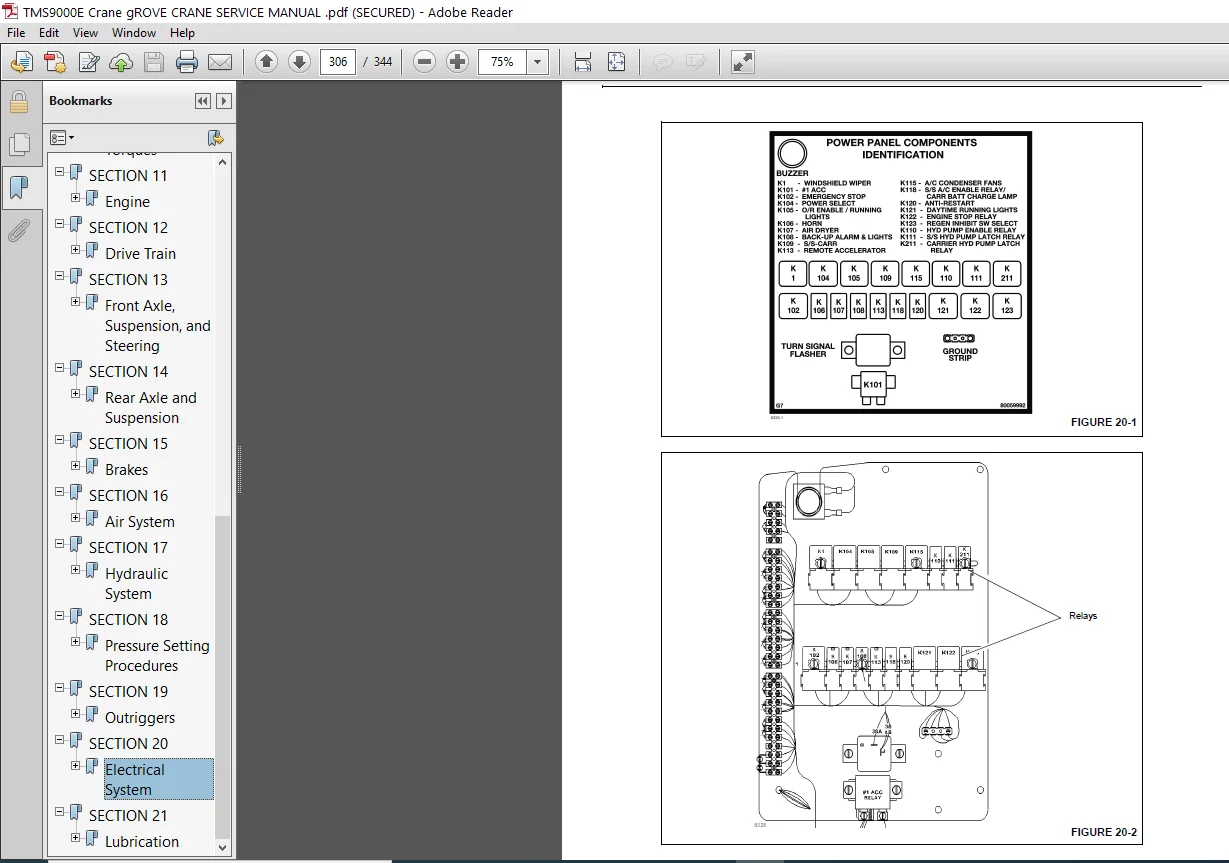
SECTION 20 Electrical System
Description 20-1
Carrier 20-1
Maintenance 20-7
General 20-7
TABLE OF CONTENTS TMS9000E SERVICE MANUAL
TOC-8
General Troubleshooting 20-7
Troubleshooting Engine Starting Problems 20-8
Troubleshooting Engine Charging Problems 20-8
Troubleshooting Accessories 20-9
Troubleshooting Swivel-Caused Electrical Problems 20-9
Connector Troubleshooting 20-10
Troubleshooting Lights 20-10
Troubleshooting Gauges and Meters 20-10
Troubleshooting Alarms, Indicators, and Emergency Components 20-11
Troubleshooting Crane Components and Accessories 20-11
Tools for Troubleshooting 20-12
Alternator Replacement 20-12
Starter Replacement 20-13
Battery Replacement 20-13
Relay Panel Component Replacement 20-15
Instrument Replacement 20-15
Switch Replacement 20-15
Rocker Switch 20-15
All Other Switches 20-16
Windshield Wiper Assembly Replacement 20-16
Windshield Washer Assembly Replacement 20-18
SECTION 21 Lubrication
GENERAL 21-1
Environmental Protection 21-1
Arctic Conditions Below -18°C (0°F) 21-1
LUBRICATION POINTS 21-2
Carrier Lubrication 21-3
Hydraulic Lubrication 21-8
Superstructure Lubrication 21-9
Boom, Boom Extension, and Boom Accessories Lubrication 21-13
Boom Locking Pins Lubrication Procedure 21-14
Preparing the Crane 21-14
Lubricating Tele Locking Pin 4 21-14
Lubricating Tele Locking Pin 3 21-15
Lubricating Tele Locking Pin 1 and 2 21-16
Wire Rope Lubrication 21-17
Carwell® Rust Inhibitor 21-17
Protecting Cranes From Corrosion 21-17
Cleaning Procedures 21-18
Inspection and Repair 21-18
Application 21-19
Areas of Application 21-19
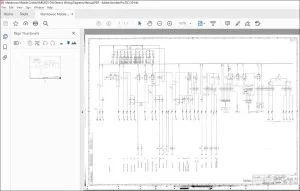
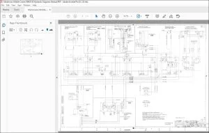
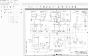
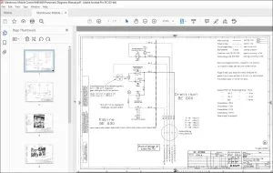
IMAGES PREVIEW OF THE MANUAL:
GROVE MANITOWOC TMS9000E CRANE SERVICE MANUAL – PDF DOWNLOAD:
PLEASE NOTE:
- This is the SAME exact manual used by your dealers to fix your vehicle.
- The same can be yours in the next 2-3 mins as you will be directed to the download page immediately after paying for the manual.
- Any queries / doubts regarding your purchase, please feel free to contact [email protected]