Grove PAT iFLEX5 Loade Moment Indicator Service Manual – PDF DOWNLOAD
$26.95
Grove PAT iFLEX5 Loade Moment Indicator Service Manual – PDF DOWNLOAD
Description
Grove PAT iFLEX5 Loade Moment Indicator Service Manual – PDF DOWNLOAD
FILE DETAILS:
Grove PAT iFLEX5 Loade Moment Indicator Service Manual – PDF DOWNLOAD
Language : English
Pages : 105
Downloadable : Yes
File Type : PDF
DESCRIPTION:
Grove PAT iFLEX5 Loade Moment Indicator Service Manual – PDF DOWNLOAD
DESCRIPTION OF SYSTEM FUNCTION:
The iFLEX5 system is a CAN bus system made up of a central microprocessor unit, operating console,
length/angle sensor, pressure transducers, and anti-two block switches. All components and sensors
are equipped with CAN bus controllers.
- The PAT Load Moment Indicator system operates on the principle of reference/real comparison. The
real value, resulting from the pressure measurement is compared with the reference data, stored in
the central processor memory and evaluated in the microprocessor. When limits are reached, an
overload warning signal is generated at the operator’s console. At the same time, the aggravating
crane movements, such as hoist up, telescope out and boom down, will be stopped. - The fixed data regarding the crane, such as capacity charts, boom weights, centers of gravity and
dimensions are stored in memory chips in the central processor unit. This data is the reference
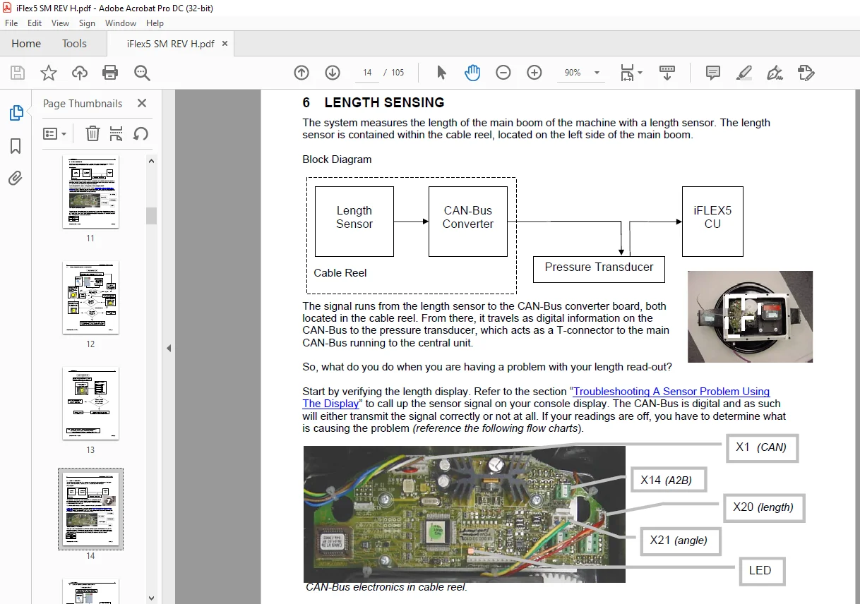
information used to calculate the operating conditions. - Boom length and boom angle are registered by the length/angle sensor, mounted inside the cable
reel, which is mounted on the boom. The boom length is measured by the cable reel cable, which also
serves as an electrical conductor for the anti two-block switches. - The crane load is measured by pressure transducer block attached to the piston and rod side of the
hoist cylinders. - The interactive user guidance considerably simplifies the input of operating modes as well as the
setting of geometry limit values.
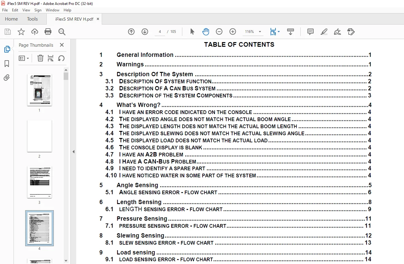
TABLE OF CONTENTS:
Grove PAT iFLEX5 Loade Moment Indicator Service Manual – PDF DOWNLOAD
1 General Information 1
2 Warnings 1
3 Description Of The System 2
3 1 DESCRIPTION OF SYSTEM FUNCTION 2
3 2 DESCRIPTION OF A CAN BUS SYSTEM 2
3 3 DESCRIPTION OF THE SYSTEM COMPONENTS 3
4 What’s Wrong? 4
4 1 I HAVE AN ERROR CODE INDICATED ON THE CONSOLE 4
4 2 THE DISPLAYED ANGLE DOES NOT MATCH THE ACTUAL BOOM ANGLE 4
4 3 THE DISPLAYED LENGTH DOES NOT MATCH THE ACTUAL BOOM LENGTH 4
4 4 THE DISPLAYED SLEWING DOES NOT MATCH THE ACTUAL SLEWING ANGLE 4
4 5 THE DISPLAYED LOAD DOES NOT MATCH THE ACTUAL LOAD 4
4 6 THE CONSOLE DISPLAY IS BLANK 4
4 7 I HAVE AN A2B PROBLEM 4
4 8 I HAVE A CAN-BUS PROBLEM 4
4 9 I NEED TO IDENTIFY A SPARE PART 4
4 10 I HAVE NOTICED WATER IN SOME PART OF THE SYSTEM 4
5 Angle Sensing 5
5 1 ANGLE SENSING ERROR – FLOW CHART 6
6 Length Sensing 8
6 1 LENGTH SENSING ERROR – FLOW CHART 9
7 Pressure Sensing 11
7 1 PRESSURE SENSING ERROR – FLOW CHART 11
8 Slewing Sensing 12
8 1 SLEW SENSING ERROR – FLOW CHART 13
9 Load sensing 14
9 1 LOAD SENSING ERROR – FLOW CHART 14
10 No console display 15
11 A2B Problem 16
12 cann-bus communication 17
12 1 E61 17
12 1 1 E61 – Flow Chart 18
12 2 E62 19
12 3 E63 19
12 4 E64 19
12 4 1 E64 – Flow Chart 20
12 5 E65 20
13 Troubleshooting a sensor problem using the display 21
14 iFLEX5 Boom Control System (BCS) 24
14 1 RT9000E / RT800E BASICS 24
14 1 1 Terminology: 24
14 1 2 Components: 24
14 1 3 Manual / Auto Mode: 24
14 2 TELE SEQUENCE: 26
14 3 IFLEX5 BCS DIGITAL INPUTS: 26
14 4 RT9000E / RT800E IFLEX5 BCS DIGITAL OUTPUTS: 27
Service Manual iFLEX5
© Hirschmann Rev H 11/6/08 190154_H
14 5 IFLEX5 BCS ANALOG INPUTS AND PWM OUTPUTS: 29
14 6 IFLEX5 BCS TEST DISPLAY: 31
14 7 BOOM OUT OF SEQUENCE: 32
14 8 TELE ROD DRAIN VALVE: 32
14 9 TELE TWO STAGE RELIEF VALVE: 32
14 10 HYDRAULIC LUFFING BOOM EXTENSION: 33
15 Drawings 34
15 1 COMPONENTS OF THE LMI SYSTEM PAT IFLEX5 34
15 2 BLOCK DIAGRAM 35
15 3 ELECTRICAL SYSTEM DIAGRAM STANDARD SYSTEM 36
15 3 1 Central Unit to Crane and Console Wiring Diagram 36
15 3 2 Cable Reel (length/angle sensor) Wiring Diagram 37
15 3 3 Boom Extension Anti-two Block Wiring Diagram 38
15 4 MAIN CENTRAL UNIT CONNECTOR 38
15 5 ELECTRICAL SYSTEM DIAGRAM BOOM CONTROL SYSTEM 39
15 5 1 Central Unit to Crane Interface Wiring Diagram 39
15 5 2 Console and Sensor Wiring Diagram 40
15 5 3 Cable Reel (LWG520/0002) Wiring Diagram 42
15 5 4 Luffer Extension Wiring Diagram 43
16 Spare Part Listings 44
16 1 CENTRAL UNIT, IFLEX5 PART NO 021-020-060-003 44
16 2 GRAPHIC CONSOLE ASSY, VERTICAL PART NO 050-350-061-356 45
16 3 GRAPHIC CONSOLE ASSY, PART NO 050-350-061-376 46
16 4 CABLE REEL, LWG508 PART NO 068-508-060-001 47
16 5 CABLE REEL, LWG521 PART NO 068-521-060-002 49
16 6 CABLE REEL, LWG152 PART NO 067-152-060-056 50
16 7 PRESSURE TRANSDUCER BLOCK, DAV314/0014 PART NO 044-314-060-014 51
16 8 CABLE ASSEMBLY 11M, PART NO 031-010-101-007 51
16 9 WIRING HARNESS STANDARD, PART NO 031-010-100-549 51
16 10 WIRING HARNESS BOOM CONTROL, PART NO 031-010-100-554 52
16 11 CABLE ASSEMBLY, 14M PART NO 031-010-100-555 52
16 12 TRS05 REPEATER, RADIO WINDSPEED KIT 031-300-104-087 53
17 Service Screen For Sensor Calibration 54
17 1 ACTIVATING THE SERVICE SCREEN FOR SENSOR CALIBRATION 54
17 2 ZERO-SETTING THE TRANSDUCER INPUTS 55
17 3 ZERO-SETTING THE SLEWING INPUTS 55
17 4 LENGTH SENSOR CALIBRATION PROCEDURE 56
17 4 1 Cable Reel LWG508 Adjustment Procedure 56
17 4 2 Length Sensor Adjustment Procedure 57
17 4 3 Cable Reel Length Cable Replacement Procedure 58
17 5 ANGLE SENSOR CALIBRATION PROCEDURE 59
17 6 ZERO-SETTING THE SLEW POTENTIOMETER 61
18 Error Codes 62
19 Troubleshooting Moisture 72
19 1 WATER INGRESS 72
19 2 CONDENSATION 73
IMAGES PREVIEW OF THE MANUAL:
Questions? Email us: [email protected]
https://vimeo.com/861560831?share=copy
PLEASE NOTE:
- This is the SAME manual used by the dealers to troubleshoot any faults in your vehicle. This can be yours in 2 minutes after the payment is made.
- Contact us at [email protected] should you have any queries before your purchase or that you need any other service / repair / parts operators manual.
S.V