Grove TMS900E Superstructure Operator’s & Safety Handbook Manual – PDF DOWNLOAD
Original price was: $86.95.$29.95Current price is: $29.95.
Grove TMS900E Superstructure Operator’s & Safety Handbook Manual – PDF DOWNLOAD
Description
Grove TMS900E Superstructure Operator’s & Safety Handbook Manual – PDF DOWNLOAD
FILE DETAILS:
Grove TMS900E Superstructure Operator’s & Safety Handbook Manual – PDF DOWNLOAD
Language : English
Pages : 590
Downloadable : Yes
File Type : PDF
Size: 29.4 MB
DESCRIPTION:
Grove TMS900E Superstructure Operator’s & Safety Handbook Manual – PDF DOWNLOAD
FOREWORD:
- This handbook has been compiled to assist you in properly operating and maintaining your
Grove Crane. - Before placing the crane in service, take time to thoroughly familiarize yourself with the contents
of this manual. After all sections have been read and understood, retain the manual for
future reference in a readily accessible location. - The Grove Crane has been designed for maximum performance with minimum maintenance.
With proper care, years of trouble-free service can be expected. - Constant improvement and engineering progress makes it necessary that we reserve the right to
make specification and equipment changes without notice. - Grove Worldwide and our Dealer Network want to ensure your satisfaction with our products
and customer support. Your local dealer is the best equipped and most knowledgeable to assist
you for parts, service and warranty issues. They have the facilities, parts, factory trained personnel,
and the information to assist you in a timely manner. We request that you first contact them
for assistance. If you feel you need factory assistance, please ask the dealer’s service management
to coordinate the contact on your behalf. - Engine operating procedures and routine maintenance procedures are supplied in a separate
manual with each crane, and should be referred to for detailed information.
Information in this manual does not replace federal, state, or local regulations, safety codes, or
insurance requirements. - Grove remains committed to providing reliable products that enable users and operators to
safely lift and position loads. Grove has been an industry leader in the incorporation of operational
aids into the design of its cranes. Federal law requires that cranes be properly maintained
and kept in good working condition. The manuals that Grove provides that are specific for each
crane and the manufacturer’s manuals for the operational aids shall be followed.
IMAGES PREVIEW OF THE MANUAL:
TABLE OF CONTENTS:
Grove TMS900E Superstructure Operator’s & Safety Handbook Manual – PDF DOWNLOAD
1 1 GENERAL 1-1
1 2 OPERATOR’S INFORMATION 1-2
1 3 OPERATOR’S QUALIFICATIONS 1-2
1 4 CRANE STABILITY/STRUCTURAL STRENGTH 1-3
1 4 1 Load Charts 1-4
1 4 2 Work Site 1-5
1 4 3 Lifting Operations 1-5
1 4 4 Counterweight 1-8
1 4 5 Multiple Crane Lifts 1-8
1 5 SAFE LOAD INDICATING (SLI) SYSTEMS 1-9
1 5 1 Two-Blocking 1-9
1 6 ELECTROCUTION HAZARD 1-10
1 6 1 Set-Up and Operation 1-12
1 6 2 Electrocution Hazard Devices 1-12
1 6 3 Electrical Contact 1-14
1 6 4 Special Operating Conditions and Equipment 1-14
1 7 CRUSHING HAZARDS 1-15
1 8 TRAVELING 1-16
1 9 MAINTENANCE 1-17
1 9 1 Service and Repairs 1-18
1 9 2 Lubrication 1-18
1 9 3 Tires 1-19
1 10 BATTERIES 1-19
1 11 ENGINE 1-20
1 12 WORK PRACTICES 1-20
1 12 1 Crane Access 1-20
1 12 2 Job Preparation 1-21
1 13 COLD WEATHER OPERATION 1-21
1 14 INSTRUCTIONS FOR AIR SUSPENSION SYSTEM 1-22
2 1 OVERVIEW OF THE OPERATING AND DISPLAY INSTRUMENTS 2-1
2 1 1 Overview of the Crane Section 2-1
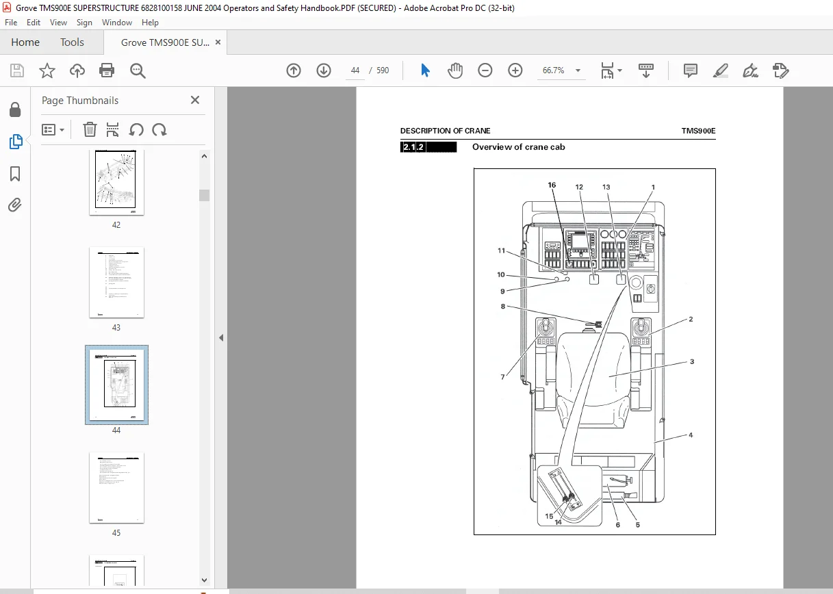
2 1 2 Overview of Crane Cab 2-4
2 1 3 Front Instrument Panel 2-6
2 1 4 Control Consoles 2-19
2 1 5 Control Lever Configuration 2-21
2 1 6 Crane Control Plug-In Module 2-23
2 1 7 Behind Crane Driver’s Seat 2-32
2 1 8 Control Box for Emergency Operation without Crane Control 2-33
2 2 FUNCTIONAL DESCRIPTION OF THE DISPLAY AND OPERATING
INSTRUMENTS FOR CRANE WORK 2-35
2 2 1 Diesel Engine 2-35
2 2 3 Outrigger, Outrigger Pressure Indicator, Electronic Level 2-42
2 2 4 Hoists 2-47
2 2 5 Slewing Gear 2-49
2 2 6 Derricking Gear 2-51
2 2 7 Telescoping Gear 2-53
2 2 8 Safe Load Indicator (SLI) 2-62
2 2 9 Hydraulic System 2-72
2 2 10 Electric, Lighting, Windscreen Wiper/Washing System 2-74
2 2 11 Crane Cab Heating System 2-76
2 2 12 Air-Conditioning System (Additional Equipment) 2-78
2 2 13 Other Operating Instruments in the Crane Cab 2-79
2 2 14 Control Box for Emergency Operation without Crane Control 2-83
2 3 FUNCTIONAL DESCRIPTION OF THE DISPLAY AND OPERATING
ELEMENTS FOR DRIVING FROM INSIDE THE CRANE CAB 2-85
2 3 1 Diesel Engine 2-85
2 4 FUNCTIONAL DESCRIPTION OF THE SAFETY DEVICES 2-86
2 4 1 Safe Load Indicator (SLI) 2-86
2 4 2 Lowering Limit Switch 2-88
2 4 3 Lifting Limit Switch 2-89
2 4 4 Dead Man’s and Seat Contact Switches 2-91
3 1 CHECKING THE TRUCK CRANE BEFORE WORKING WITH THE
CRANE 3-1
3 1 1 Condition for Working with a Truck Crane Supported on Outriggers 3-1
3 1 2 Condition for Working with a Free on Wheels Truck Crane 3-5
3 1 3 Checking the Level of Windscreen Washing System 3-10
3 1 4 Checking Safety Equipment 3-13
3 1 5 Preheating the Hydraulic Oil 3-16
3 1 6 Switching Off the Boom Floating Position 3-17
3 1 7 Switching Off Boom Pre-Tensioning 3-17
3 1 8 Switching Off Slewing Gear Freewheel 3-19
3 1 9 Locking/Unlocking the Superstructure 3-20
3 1 10 Start Warm Diesel Engine 3-21
3 1 11 Checks After Starting the Diesel Engine 3-25
3 1 12 Shutting Down the Diesel Engine 3-27
3 2 OPERATING THE SAFE LOAD INDICATOR (SLI) 3-28
3 2 1 Switching on the SLI 3-28
3 2 2 Setting Rigging Mode 3-31
3 2 3 Checks Before Working with the Crane 3-38
3 2 4 During Crane Work 3-40
3 2 5 Monitoring the Overall Height 3-47
3 3 CRANE WORK WITH MAIN BOOM 3-52
3 3 1 External Influences During Crane Operation 3-52
3 3 2 Permissible Slewing Ranges and Working Positions for Crane
Work 3-57
3 3 3 Main Hoist 3-59
3 3 4 Auxiliary Hoist (Additional Equipment) 3-63
3 3 5 Derricking Gear 3-65
3 3 6 Slewing Gear 3-67
3 3 7 Telescoping Gear 3-73
3 3 8 Fast Speed 3-112
3 3 9 Special Menus on the Crane Control Display 3-113
3 3 10 Setting a Constant Engine Speed 3-122
3 3 11 Inclining Crane Cab 3-123
3 3 12 Cooling the Hydraulic Oil 3-124
3 3 13 Possible Movement Combinations 3-125
3 4 WORK BREAK 3-126
3 4 1 Short Work Break 3-126
3 4 2 Work Breaks Lasting More Than 8 Hours 3-126
3 5 CRANE CAB HEATING AND VENTILATION 3-128
3 5 1 Heating the Crane Cab 3-128
3 5 2 Ventilating the Crane Cab 3-135
3 6 AIR CONDITIONING SYSTEM (ADDITIONAL EQUIPMENT) 3-136
3 6 1 To Switch On 3-136
3 6 2 Setting the Air Flow 3-137
3 6 3 To Switch Off 3-137
3 6 4 Air Conditioning 3-138
4 1 CHECKLISTS FOR RIGGING WORK FOR CRANE OPERATION WITH MAIN
BOOM 4-1
4 1 1 Rigging 4-1
4 1 2 Unrigging 4-4
4 2 CHOOSING A SUITABLE SITE 4-6
4 2 1 Load Bearing Capacity of the Ground and the Outrigger 4-6
4 2 2 Safe Distance from Banks and Pits 4-9
4 2 3 Safe Distance from Electrical Lines 4-10
4 2 4 Earthing the Truck Crane 4-13
4 3 OUTRIGGER 4-13
4 3 1 Extending the Outrigger 4-14
4 3 2 Retracting the Outrigger 4-15
4 3 3 Permissible Outrigger Spreads 4-16
4 3 4 Preparing the Truck Crane 4-19
4 3 5 Securing/Releasing Outrigger Beam for Crane Operations 4-20
4 4 RIGGING WORK ON THE MAIN BOOM 4-25
4 4 1 Hook Block and Headache Ball Stowage 4-25
4 4 2 Hook Block on a Separate Vehicle 4-26
4 4 3 Reeving and Unreeving the Hoist Rope 4-27
4 4 4 Driving with a Rigged Crane 4-35
4 4 5 Driving Route 4-35
4 4 6 Driving the Rigged Truck Crane 4-36
4 4 7 Possible Reeving on the Main Boom for Standard Design with 6
Sheaves 4-37
4 4 8 Anemometer 4-40
5 1 COUNTERWEIGHT RIGGING 5-1
5 1 1 Counterweight Parts 5-1
5 1 2 Counterweight Versions 5-2
5 1 3 Slinging Points on the Counterweight Sections 5-5
5 1 4 Rigging the Counterweight 5-8
5 1 5 Unrigging the Counterweight 5-11
5 1 6 Lower 4300 Lb Base plate on the Counterweight Platform 5-13
5 1 7 Check the Position of the Locking Pins 5-14
5 1 8 Assembling the Counterweight Version 5-16
5 1 9 Counterweight Lifting Unit 5-21
5 1 10 Removing/Installing the Counterweight Sections on the Turntable 5-28
5 1 11 Locking/Unlocking the 4300 Lb Counterweight Sections 5-30
5 1 12 Slewing With the Rigged Counterweight 5-32
6 2 WHAT TO DO IN THE EVENT OF A MALFUNCTION WHEN WORKING
WITH THE CRANE 6-3
6 3 ELECTRICAL SYSTEM 6-3
6 3 1 Plug-in Modules and Consoles 6-3
6 3 2 Fuses 6-6
6 3 3 SLI Fuses 6-11
6 4 TROUBLESHOOTING AND REMEDY 6-13
6 4 1 Vehicle Engine Malfunctions During the Crane Operations 6-13
6 4 2 Main Hoist Malfunctions 6-14
6 4 3 Auxiliary Hoist Malfunctions 6-16
6 4 4 Derricking Gear Malfunctions 6-18
6 4 5 Telescoping Gear Malfunctions 6-20
6 4 6 Slewing Gear Malfunctions 6-25
6 4 7 Malfunctions at the Counterweight Hoist Unit 6-26
6 4 8 Hydraulic System/Hydraulic Oil Cooler Malfunctions 6-27
6 4 9 Outrigger Malfunctions 6-27
6 4 10 Crane Control Malfunctions 6-28
6 4 11 Malfunctions on the SLI 6-29
6 4 12 Emergency Retract Operation 6-43
6 5 ERROR MESSAGES ON CRANE CONTROL DISPLAY 6-58
6 5 1 Meaning of Displayed Symbols 6-58
6 5 2 Connections for the Crane Control Units 6-75
6 5 3 Sub-Menu Emergency Program Telescoping 6-81
6 5 4 Enter Telescope Status after Emergency Operation 6-91
6 5 5 Emergency Operation in Case of the Crane Control Failure 6-94
7 1 1 Turntable 7-1
7 1 2 Crane Operator’s Cab 7-1
7 1 3 Crane Engine and Hydraulic System 7-1
7 1 4 Control System 7-2
7 1 5 Main Boom 7-2
7 1 6 Telescoping Gear 7-2
7 1 7 Hoists 7-3
7 1 8 Slewing Gear 7-4
7 1 9 Derricking Cylinder 7-4
7 1 10 Electrical System 7-4
7 1 11 Counterweight 7-4
7-1-12 Safety Equipment 7-5
7 2 TECHNICAL DATA 7-5
7 2 1 Maximum Load Bearing Capacity (DIN/ISO/EN) 7-5
7 2 2 Max Lifting Capacity (85%) 7-5
7 2 3 Dimensions, Weights, and Axle Load 7-6
7 2 4 Dimensions and Weights of Removable Parts 7-9
7 2 5 Technical Data for Superstructure 7-128 1 ABOUT THESE OPERATING INSTRUCTIONS 8-1
8 2 BASIC SAFETY INSTRUCTIONS 8-2
8 2 1 Warnings and Symbols 8-2
8 3 PROPER USE 8-3
8 4 ORGANIZATIONAL MEASURES 8-5
8 5 PERSONNEL QUALIFICATIONS 8-7
8 6 SAFETY INSTRUCTIONS FOR TRUCK CRANE WORK 8-8
8 7 SPECIFICATIONS IN US UNITS OF MEASUREMENT 8-10
9 1 IN METRIC UNITS
9 1 1 Two-Stage Swingaway Lattice Extension and Boom Extension 9-1
9 1 2 Auxiliary Single-Sheave Boom Top 9-1
9 2 IN US UNITS 9-2
9 2 1 Two-Stage Swingaway Lattice Extension and Boom Extension 9-2
9 2 2 Auxiliary Single-Sheave Boom Top 9-2
10 1 ADDITIONAL OPERATING AND DISPLAY ELEMENTS 10-1
10 1 1 In the Crane Cabin 10-2
10 1 2 Operating and Display Instruments on the Lattice Extension 10-4
10 2 IDENTIFICATION OF THE TWO-STAGE SWINGAWAY LATTICE
EXTENSION 10-5
10 3 ASSEMBLY OF THE LATTICE EXTENSIONS 10-7
10 4 CENTERS OF GRAVITY FOR SLINGING 10-8
10 4 1 Manual Extension 10-8
10 4 2 Hydraulic Extension 10-9
10 5 CHECKLISTS FOR RIGGING WORK 10-9
10 5 1 Overview of the Required Rigging Work 10-9
10 5 2 Installing the (Two-Stage) Swingaway Lattice Extension 10-10
10 5 3 Uninstalling (Two-Stage) Swingaway Lattice Extension 10-12
10 5 4 Rigging the 33 ft Swingaway Lattice Extension 10-13
10 5 5 Unrigging the 33 ft Swingaway Lattice Extension 10-17
10 5 6 Rigging the 56 ft Two-Stage Swingaway Lattice Extension 10-21
10 5 7 Unrigging the 56 ft Two-Stage Swingaway Lattice Extension 10-25
10 6 DESCRIPTION OF RIGGING WORK 10-30
10 6 1 Preparing the Truck Crane for Rigging 10-30
10-6-2 Checking the Transport Condition 10-32
10 6 3 Hose Drum for Hydraulic Supply 10-35
10 6 4 Folding the Run-Up Rail Out/In 10-38
10 6 5 Connections with Folded Lattice Extension 10-39
10 6 6 Pin Connections on the Main Boom Head 10-47
10 6 7 Pin Connections on the Lattice Extension 10-51
10 6 8 Swinging the Lattice Extension onto the Main Boom Head 10-53
10 6 9 Swiveling the Lattice Extension when Rigging 10-54
10 6 10 Electrical Connections on the Lattice Extension 10-56
10 6 11 Establishing/Disconnecting the Hydraulic Connection 10-58
10 6 12 Folding Out/In the Deflection Sheaves on the 33 ft Section 10-59
10 6 13 Positioning/Removing the Hoist Cable 10-62
10 6 14 Lifting Limit Switch on the Lattice Extension 10-64
10 6 15 Anemometer on the Lattice Extension 10-66
10 6 16 Derricking the Lattice Extension 10-67
10 6 17 Setting the Folding Offsettable Swingaway Extension 10-68
10 6 18 Transportation on a Separate Vehicle 10-70
10 7 RAISING AND SETTING DOWN THE MAIN BOOM WITH RIGGED LATTICE
EXTENSION 10-71
10 8 TELESCOPING WITH RIGGED LATTICE EXTENSION 10-71
10 9 OPERATION WITH THE LATTICE EXTENSION 10-73
10 9 1 SLI Shutdown 10-73
10-9-2 Procedure if the Permissible Wind Speed is Exceeded 10-74
10 10 TURNING LOADS WITH THE LATTICE EXTENSION 10-75
10 10 1 Prerequisites 10-75
10 10 2 Setting SLI 10-76
10 11 DRIVING WITH RIGGED CRANE AND INSTALLED LATTICE
EXTENSION 10-80
10 11 1 Driving Route 10-80
10 11 2 Traveling with Hydraulic Luffing or Manually Offsettable Boom
Extension and/or Inserts Erected 10-81
10 11 3 Driving the Rigged Crane 10-82
10 12 MALFUNCTION WHEN WORKING WITH LATTICE EXTENSION 10-84
10 13 MAINTENANCE WORK 10-85
10 13 1 Modules in Need of Protection During Cleaning Work 10-85
10 13 2 Maintenance Work M1, Monthly 10-86
11 1 IDENTIFICATION AND SLINGING POINTS
11 1 1 Identification 11-1
11 1 2 Slinging Points 11-2
11 2 ASSEMBLY OF BOOM EXTENSIONS 11-3
11 3 CHECKLISTS FOR RIGGING WORK 11-4
11 3 1 Rigging the 72 ft/89 ft Boom Extension 11-4
11 3 2 Unrigging the 72 ft/89 Boom Extension 11-8
11 4 DESCRIPTION OF RIGGING WORK 11-11
11 4 1 Installing/Removing 16 ft Sections 11-11
11 4 2 Installing/Removing The Two-stage Swingaway Lattice Extension For
The Boom Extension 11-12
11 4 3 Hydraulic Connection at the Boom Extension 11-13
11 4 4 Electrical Connection at the Boom Extension 11-16
11 4 5 Unfolding/Folding the Deflection Sheave on the 16 ft Section 11-18
11 4 6 Positioning/Removing the Hoist Cable 11-19
11 5 DRIVING WITH RIGGED CRANE AND RIGGED BOOM
EXTENSION 11-19
11 5 1 Driving Route 11-20
11 5 3 Driving the Rigged Crane 11-21
11 6 MAINTENANCE WORK 11-21
11 6 1 Maintenance Work, M1, Monthly 11-21
12 1 IDENTIFICATION 12-1
12 2 INSTALLING/REMOVING AUXILIARY SINGLE-SHEAVE BOOM TOP 12-2
12 2 1 Installing Auxiliary Single-Sheave Boom Top 12-2
12 2 2 Removing the Auxiliary Single-Sheave Boom Top 12-3
12 3 RIGGING THE AUXILIARY SINGLE-SHEAVE BOOM TOP 12-4
12 3 1 Rigging in Transport Position 12-4
12 3 2 Rigging in Working Position 12-5
12 3 3 Attaching and Removing Hoist Cable 12-6
12 3 4 Possible Reeving Methods on the Auxiliary Single-Sheave Boom
Top 12-6
12 3 5 Lifting Limit Switch and Anemometer 12-7
12 4 TURNING LOADS WITH THE AUXILIARY SINGLE-SHEAVE BOOM
TOP 12-8
12 5 DRIVING WITH RIGGED CRANE AND INSTALLED AUXILIARY SINGLESHEAVE
BOOM TOP 12-12
Customer Support: [email protected]
PLEASE NOTE:
- This is the same manual used by the DEALERSHIPS to SERVICE your vehicle.
- The manual can be all yours – Once payment is complete, you will be taken to the download page from where you can download the manual. All in 2-5 minutes time!!
- Need any other service / repair / parts manual, please feel free to contact us at heydownloadss @gmail.com . We may surprise you with a nice offer
S.V