Haas VMC Mill & Lathe Electrical Service Manual – 96-0284 Rev H PDF
Original price was: $95.00.$16.95Current price is: $16.95.
Official Haas Automation electrical service manual for Mill and Lathe CNC machines — 96-0284 Rev H (January 2010). Covers complete electrical troubleshooting, PCB replacement, solenoids, Smart Amplifier, Smart Vector Drive, front panel, fuse/line voltage, cable list, wiring diagrams, ~170 alarm codes with causes and fixes, and full parameter list including ballscrew and thermal compensation. 233 pages, instant PDF download.
Description
Haas VMC Mill & Lathe Electrical Service Manual – 96-0284 Rev H PDF DOWNLOAD
DESCRIPTION
Haas Automation Mill & Lathe Electrical Service Manual (PDF) — 96-0284 Rev H
This is the official Haas Automation factory electrical service manual for Haas Mill and Lathe CNC machines — published under document number 96-0284 Revision H, January 2010 by Haas Technical Publications (Haas Automation Inc., Oxnard CA). This is the authorised reference used by Haas Factory Outlet (HFO) service technicians for all electrical troubleshooting, PCB replacement, alarm diagnosis, parameter configuration, and wiring work on Haas vertical machining centres (VMC), horizontal machining centres (HMC), and lathes.
Whether you’re a CNC service engineer diagnosing a Haas VMC alarm 119 overvoltage fault, a maintenance technician replacing a Haas MOCON, I/O PCB, or Power PCB, or a machine shop engineer configuring servo gain parameters or ballscrew compensation, this Haas electrical service manual PDF delivers the exact factory-level data you need — instantly downloadable and available for use on any device at the machine.
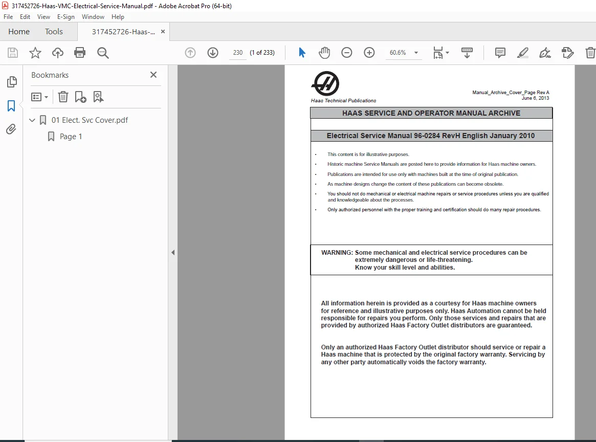
⚠️ This is the archive/rev H edition of the manual. As stated by Haas, this publication is intended for use with machines built at the time of original publication. Always verify applicability to your specific machine serial number.
📋 File Details
| Detail | Info |
|---|---|
| Manual Title | Haas Mill and Lathe Electrical Service Manual |
| Document Number | 96-0284 Rev H |
| Publisher | Haas Automation Inc., Oxnard CA 93030 |
| Models Covered | Haas VMC (Vertical Machining Centres), HMC (Horizontal Machining Centres), Lathes |
| Edition | January 2010 (Revision H) |
| Language | English |
| Pages | 233 Pages |
| PDF Quality | Original factory digital file — clean, US Letter format, fully readable |
| File Size | ~7.1 MB |
Table of Contents
Safety
- Lockout/tagout procedure — locking circuit breaker in OFF position
- High-voltage panel warning — qualified electricians only
- Working safely around Haas electrical cabinet
General Electrical Troubleshooting
Machine Not Running:
- Machine cannot be powered on — input voltage, main circuit breaker, overvoltage fuses, Power Off button wiring, Auto Off relay to I/O PCB, 24V transformer (T5) and K1 contactor checks, I/O PCB, Power PCB
- Machine powers on but turns off by itself — Settings 1 & 2, alarm history (overvoltage/overheat), AC power supply, low voltage power supply, K1 contactor, MOTIF/MOCON PCB, Parameter 57
- Machine turns on, keyboard beeps, but no LCD/CRT display — power connections to LCD, video cable, Video PCB, processor lights
- Machine turns on, LCD works, but keyboard keys do not work — keyboard cable (700), SKB
- Additional machine-not-running fault scenarios
Electrical Alarm Troubleshooting — systematic approach to alarm-driven fault finding
Line Voltage Adjustments
- Electrical connections (input wiring requirements)
- Line voltage measurement and tap adjustment procedures
Fuse Replacement
- Overvoltage fuses — identification, location, and replacement
Front Panel
- SL-10 Pendant Components Access
- LCD Assembly Replacement — step-by-step
- Jog Handle — replacement procedure
- Power ON/OFF Switches — replacement
- Emergency Stop Switch — replacement
- Keyboard Beeper — replacement
- Lamp ON/OFF Switch — replacement
- Switch Replacement — general procedure
- Spindle Load Meter — replacement
- Keypad Replacement — step-by-step
- Serial Keyboard Interface Replacement
Solenoids
- Tool Release Piston (TRP) Air Solenoid Assembly — horizontal and vertical machines
- Spindle Lube Air Solenoid — replacement and testing
- Pneumatic Chuck / Turret Clamp / Unclamp Solenoid (Lathe) — replacement
Smart Amplifier
- Smart amplifier description, identification (P/N 93-5550J 30A / 93-3551J 45A)
- Replacement and fault diagnosis procedures
Smart Vector Drive
- Haas Vector Drive unit description
- Replacement and troubleshooting
PCB Replacement
Microprocessor Assembly:
- Motor Controller (MOCON) — replacement procedure
- Video / Keyboard PCB — replacement
- Microprocessor PCB (68ECO30) — replacement
- Input/Output Assembly — replacement
- Power Transformer Assembly (T1) — replacement
Power Supply Assembly:
- Low Voltage Power Supply — replacement
- RS-232 Serial Interface — replacement
Spare User M Code Interface
- M Function Relays (M-Fin) — wiring and configuration
- M-Fin discrete input configuration
- Wiring the relays
Switches — switch types, testing, and replacement
Control Memory
- Memory battery replacement and backup procedures
Diagnostic Data
Discrete Inputs/Outputs (Lathe):
| # | Discrete Input Name |
|---|---|
| 1023 | Safety Switch |
| 1024 | M Code Finish* / APC Pal Clamp |
| 1025 | Over Voltage (Mini-Mill P.S. Fault) |
| 1026 | Low Air Pressure |
| 1027 | Low Lube Press |
| 1028 | Regen Over Heat |
| 1029 | Drawbar Open |
| 1030 | Drawbar Closed |
| 1034 | Low Trans Oil Prs |
| 1035 | Spare 1 / APC Door |
| … | And many more inputs/outputs |
Discrete Inputs/Outputs (Mills) — full I/O register list including:
- Powered Servos, Coolant Pump On, Auto Power Off, Spindle Motor Fan
- Tool Changer In/Out, Rotate TC CW/CCW
- Spindle Hi/Lo Gear, Unclamp Tool
- M21/M22/M23 outputs, TSC Coolant, Beacon indicators, Conveyor control
- APC chain drive, pallet clamp, APC door controls (APC-equipped machines)
Inputs 2 (Servo System):
- X/Y/Z/A/B Axis Z-Channel inputs
- Home switches (X, Y, Z, A, B)
- Overheat and Drive Fault signals (X/Y/Z/A/B)
- Haas Vector Drive inputs: Spindle Forward/Reverse/Lock, Spindle at Speed, Spindle Stopped/Fault/Locked/Cable Fault/Overheat
- SMTC (Side-Mount Tool Changer) discrete inputs 2 and outputs 2
Cable List (Pages 37–47) — complete cable reference table for all machine interconnects
PCBs, Cable Locations, and Diagrams (Pages 48–79)
- Microprocessor PCB — connector layout diagram
- Servo System Block Diagram
- Brushless Servo Amplifier (P/N 32-5550F) — diagram
- Smart Amplifier (P/N 93-5550J 30A / 93-3551J 45A) — diagram
- System Block Diagram — High/Low Voltage
- Power PCB Version K/L — full diagram
- Office Mill Power Supply — diagram
- I/O PCB Version W, Z, AA, AB — full connector diagram
- Discrete Inputs (I/O PCB) — pin-by-pin reference
- Discrete Outputs (I/O PCB) — pin-by-pin reference
- Serial Keyboard Interface PCB with Handle Jog (34-4241D)
- Video & Keyboard PCB w/ Ethernet & USB Drive
- MOCON PCB
- RS-232 Port #1 PCB
- Wye-Delta Switch Assemblies
- M Code Relay Board
- Hydraulic PCB
- TSC Motor Drive / High Pressure Coolant PCB
- Haas Vector Drive Unit
- Quad APC (32-3078A) PCB
- Renishaw Tool Presetter (Lathe)
- Operator Pendant
- Circuit Breakers — identification and ratings
- Horizontal Machine Control Cabinet Wiring Diagram
- Vertical Machine Control Cabinet Wiring Diagram
- Lathe Control Cabinet Wiring Diagram
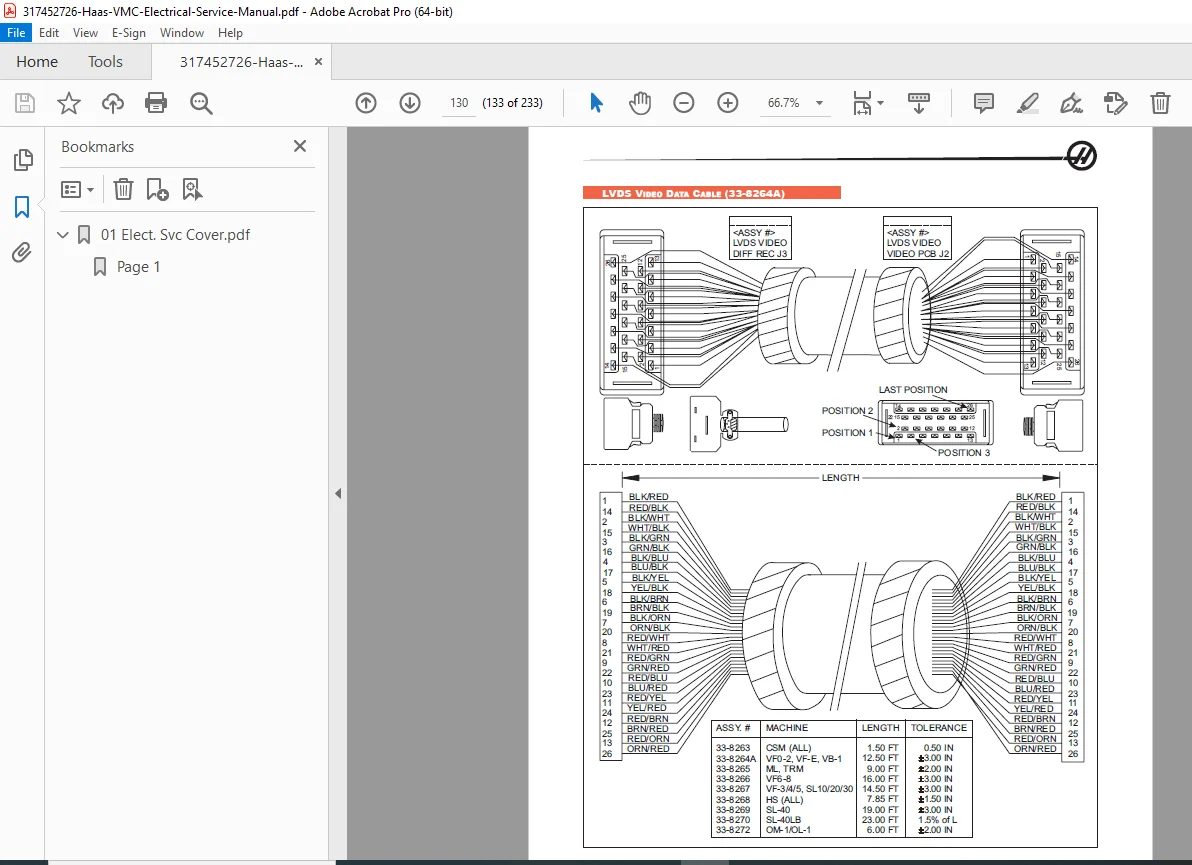
Cables (Pages 80–132) — complete illustrated cable routing, pinout, and connector reference for all machine cable assemblies
Alarms (Pages 133–179) — ~170 alarm codes with full descriptions, causes, and corrective actions. Sample alarms include:
| Alarm | Description |
|---|---|
| 108 | X Servo Error Too Large |
| 109 | Y Servo Error Too Large |
| 110 | Z Servo Error Too Large |
| 111 | A-Axis Fault |
| 113 | Turret Rotate Fault (Lathe) |
| 115 | Turret Rotate Fault (Mill) — check CB5, relays 1-8, 2-3, 2-4 |
| 116 | Spindle Orientation Fault — encoder, cables, belts, MOCON, vector drive, Parameter 257 |
| 117 | Spindle High Gear Fault — air pressure, CB4, solenoid, discrete inputs |
| 118 | Spindle Low Gear Fault — CB4, solenoid, gear sensor |
| 119 | Overvoltage — line voltage above max, servos off, Parameter 296/315 |
| 120 | Low Air Pressure — check incoming air (100 psi min), regulator (85 psi), I/O P12 jumper |
| 121 | Low Lube / Low Pressure — tank level, lube lines, pressure switch, I/O P13 jumper |
| 122 | Regen Overheat — line voltage high, spindle start/stop duty cycle, Parameter 297 |
| 123 | Spindle Drive Fault — shorted motor, overvoltage, overcurrent, regen load |
| 124 | Low Battery — memory battery replacement required |
| …and ~155 more alarm codes with full diagnostic and repair guidance |
Parameters (Pages 180–233)
Full parameter list including:
| Parameter | Description |
|---|---|
| 1 | X Switch A (axis enable/configuration bits) |
| 2 | X P Gain |
| 3 | X D Gain |
| 4 | X I Gain |
| 5 | X Ratio (Steps/Unit) |
| 6 | X Max Travel (Steps) |
| 7 | X Acceleration |
| 8 | X Max Speed |
| 9 | X Max Error |
| 10 | X Fuse Level |
| 11 | X Torque Preload / Back EMF |
| 12 | X Steps/Revolution (encoder count × 4) |
| 13 | X Backlash (encoder steps) |
| 14 | X Dead Zone |
| 15–28 | Y-axis equivalents of all above parameters |
| 29–42 | Z-axis equivalents of all above parameters |
| 43– | A-axis (4th axis) — including HRT 210 rotary table step calculation examples |
| 57 | Power Off at E-Stop |
| 60/61 | Turret time-out adjustments |
| 62/63 | Tool motor time-out adjustments |
| 67/70/75 | Spindle gear change time-out parameters |
| 76 | Low Air Pressure delay |
| 209 | M-Code Relay Board enable |
| 257 | Spindle Orient Offset |
| 278 | SMNT bits (Side-Mount Tool Changer) |
| 296/297 | Overvoltage/Regen overheat shutdown intervals |
| 315 | Mini Power Supply bit (Office Mill / 320V supply) |
| …and hundreds more parameters |
Ballscrew Compensation (Mills) — setup and configuration procedure
Electronic Thermal Compensation — configuration and use
Spindle Head Thermal Compensation — configuration and use
X-Axis Thermal Compensation (Lathes) — configuration and use
Common Abbreviations — reference glossary
🔧 Who Needs This Manual?
- ✅ CNC service technicians diagnosing Haas VMC electrical alarms (108–300+ range)
- ✅ Machine maintenance engineers replacing Haas MOCON, I/O PCB, Power PCB, or Vector Drive
- ✅ Workshop electricians performing Haas line voltage adjustments, fuse replacement, or solenoid service
- ✅ CNC programmers/engineers configuring servo gain, backlash, ballscrew compensation, or thermal compensation parameters
- ✅ Machine shop owners needing Haas control cabinet wiring diagrams and cable routing reference
- ✅ Anyone needing a Haas VMC electrical service manual PDF immediately without waiting for an HFO service call
Every Haas alarm code, every PCB pinout, every wiring diagram, and every parameter explained — all in one 233-page factory document you can download right now. Stop waiting for an HFO service call and start diagnosing with the same manual the technicians use. Download it instantly and have your Haas back in cut today.