Haulotte Forklift HT16 RTJ O – HT16 RTJ PRO – Operator’s manual
$23.95
Haulotte Forklift HT16 RTJ O – HT16 RTJ PRO – Operator’s manual – PDF DOWNLOAD
HT16 RTJ O – HT16 RTJ PRO –
HT46 RTJ O – HT46 RTJ PRO –
Monochrome LCD display
Description
Haulotte Forklift HT16 RTJ O – HT16 RTJ PRO – Operator’s manual – PDF DOWNLOAD
FILE DETAILS:
Haulotte Forklift HT16 RTJ O – HT16 RTJ PRO – Operator’s manual – PDF DOWNLOAD
Language : English
Pages :138
Downloadable : Yes
File Type : PDF
HT16 RTJ O – HT16 RTJ PRO –
HT46 RTJ O – HT46 RTJ PRO –
Monochrome LCD display
TABLE OF CONTENTS:
Haulotte Forklift HT16 RTJ O – HT16 RTJ PRO – Operator’s manual – PDF DOWNLOAD
Operator’s manual 1
HT16 RTJ O – HT16 RTJ PRO – HT46 RTJ O – HT46 RTJ PRO – Monochrome LCD display 1
24203 0 1
X 1
USA 2
A 3
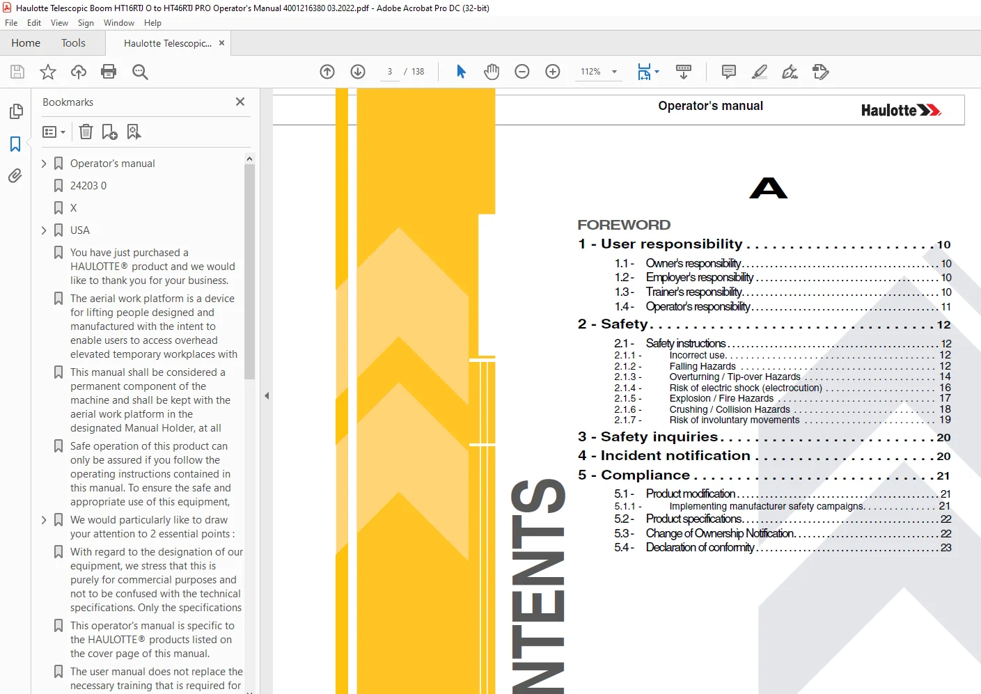
Foreword 3
1 – User responsibility 10 3
11 – Owner’s responsibility 10 3
12 – Employer’s responsibility 10 3
13 – Trainer’s responsibility 10 3
14 – Operator’s responsibility 11 3
2 – Safety 12 3
21 – Safety instructions 12 3
211 – Incorrect use 12 3
212 – Falling Hazards 12 3
213 – Overturning / Tip-over Hazards 14 3
214 – Risk of electric shock (electrocution) 16 3
215 – Explosion / Fire Hazards 17 3
216 – Crushing / Collision Hazards 18 3
217 – Risk of involuntary movements 19 3
3 – Safety inquiries 20 3
4 – Incident notification 20 3
5 – Compliance 21 3
51 – Product modification 21 3
511 – Implementing manufacturer safety campaigns 21 3
52 – Product specifications 22 3
53 – Change of Ownership Notification 22 3
54 – Declaration of conformity 23 3
B 4
Familiarization 4
1 – General safety 25 4
11 – Intended use 25 4
12 – Decal content 26 4
13 – Symbols and colors 27 4
14 – Level of severity 27 4
15 – Symbols legend and definitions 28 4
2 – Models description 29 4
3 – Primary machine components 30 4
31 – Layout 30 4
32 – Ground control box 32 4
321 – Layout 32 4
322 – Display Panel (LED’S 1 – 10) – Monochrome LCD display 36 4
3221 – Fault and alarm codes 39 4
33 – Platform control box 42 4
331 – Layout 42 4
332 – Display Panel (LED’S 101 – 117) 45 4
4 – Performance Specifications 49 4
41 – Technical characteristics 49 4
42 – Working area / Range of motion 53 4
5 – Decals and markings locations 54 4
C 4
Pre-operation inspection 4
1 – Recommendations 65 4
2 – Working area assessment 65 4
3 – Inspection and Functional test 66 4
31 – Daily inspection 66 4
4 – Safety functional checks 69 4
41 – E-Stop button check 70 4
42 – Activation of controls 70 4
43 – Fault detector 71 4
431 – Indicators/LED’s test 71 4
432 – Buzzers test 71 4
44 – Automatic engine cut-out 72 4
45 – Overload sensing system 72 4
46 – Oscillating axles (If equipped) 72 4
47 – Slope warning device 73 4
48 – Travel speed limitation 73 4
49 – Load selection system (if fitted) 74 4
D 5
Operation instructions 5
1 – Operation 75 5
11 – Introduction 75 5
12 – Major description 75 5
13 – Operation from the ground control box 75 5
14 – Operation from the platform control box 77 5
2 – Ground control box 79 5
21 – To start and stop the machine – Diesel engine 79 5
22 – To start and stop the machine – Petrol / gas (Propane) Engine 80 5
23 – Movement control 81 5
24 – Additional controls 82 5
3 – Platform control box 83 5
31 – To start and stop the machine 83 5
311 – To start the machine 83 5
3111 – To stop the engine 83 5
3112 – If engine is stopped by Stop Emission System 83 5
32 – Drive and steer control 84 5
33 – Movement control 85 5
34 – Additional controls 86 5
341 – Stop Emission System 86 5
342 – Activ’ Lighting System 86 5
343 – Dual load selector (if fitted) 87 5
4 – Rescue and emergency procedures 88 5
41 – In case of power loss 88 5
42 – To rescue operator in platform 89 5
421 – Operation of overriding system from ground control box 90 5
43 – No power available 90 5
5 – Transportation 91 5
51 – Transport configuration 91 5
52 – Machine stowage for transport – HT16 RTJ O – HT16 RTJ PRO – HT46 RTJ O – HT46 RTJ PRO 92 5
53 – Unloading 93 5
54 – Towing 94 5
541 – Brake release 94 5
542 – Adjustment after manual release 97 5
55 – Storage 98 5
56 – Lifting operation 99 5
6 – Cold Weather Recommendations 101 5
61 – Engine oil 101 5
62 – Hydraulic oil 102 5
E 6
General Specifications 6
1 – Machine dimensions 103 6
2 – Major component masses 105 6
3 – Acoustics and vibrations 105 6
4 – Wheel/Tire assembly 106 6
41 – Technical specifications 106 6
42 – Inspection and maintenance 106 6
5 – Options 108 6
51 – Platform 108 6
52 – On-board generator 109 6
521 – Description 109 6
522 – Characteristics 109 6
523 – Safety precautions 109 6
524 – Pre-operation inspection 110 6
525 – Operation 110 6
53 – Glazier’s kit 111 6
531 – Description 111 6
532 – Characteristics 111 6
533 – Safety precautions 111 6
534 – Pre-operation inspection 111 6
535 – Operation 112 6
536 – Assembly / Dis-assembly 113 6
537 – Specific decals 114 6
54 – Welder’s kit 115 6
541 – Description 115 6
542 – Characteristics 115 6
543 – Safety precautions 115 6
544 – Pre-operation inspection 115 6
545 – Operation 115 6
546 – Assembly – Dis-assembly 116 6
547 – Specific decals 117 6
55 – Plumber’s kit 118 6
551 – Description 118 6
552 – Characteristics 118 6
553 – Safety precautions 118 6
554 – Pre-operation inspection 119 6
555 – Operation 119 6
556 – Assembly – Dis-assembly 120 6
557 – Specific decals, optional 121 6
56 – Activ’ Shield Bar – SECONDARY GUARDING SYSTEM (If fitted) 122 6
561 – Description 122 6
562 – Characteristics 122 6
563 – Safety precautions 123 6
564 – Pre-operation inspection 124 6
565 – Operation 124 6
566 – Specific decals 125 6
F 7
Maintenance 7
1 – General 127 7
2 – Maintenance Schedule 128 7
3 – Inspection program 129 7
31 – General program 129 7
32 – Daily inspection 129 7
33 – Periodic inspection 130 7
34 – Reinforced inspection 130 7
35 – Major inspection 130 7
4 – Repairs and adjustments 131 7
G 7
Other information 7
1 – Conditions of warranty 133 7
2 – Subsidiary contact information 133 7
21 – California warning 134 7
H 7
Intervention register 7
1 – Intervention register 137 7
Foreword 9
You have just purchased a HAULOTTE® product and we would like to thank you for your business 9
The aerial work platform is a device for lifting people designed and manufactured with the intent to enable users to access overhead elevated temporary workplaces with the necessary tools and equipment All other uses or alterations/ modifications to 9
This manual shall be considered a permanent component of the machine and shall be kept with the aerial work platform in the designated Manual Holder, at all times 9
Safe operation of this product can only be assured if you follow the operating instructions contained in this manual To ensure the safe and appropriate use of this equipment, only trained personnel are authorised to use and carry out maintenance on 9
We would particularly like to draw your attention to 2 essential points : 9
• Comply with safety instructions 9
• use this equipment within the performance limits specified by this user manual 9
With regard to the designation of our equipment, we stress that this is purely for commercial purposes and not to be confused with the technical specifications Only the specifications in this manual should be used to study the suitability of the equ 9
This operator’s manual is specific to the HAULOTTE® products listed on the cover page of this manual 9
The user manual does not replace the necessary training that is required for all of this machine’s operators HAULOTTE® has compiled this manual to assist in safe and efficient operation of the products covered in the manual 9
The manual must be available to all operators and must be kept in a legible condition Additional copies can be ordered from HAULOTTE Services® 9
Stay Safe and keep working with HAULOTTE® ! 9
For online reference and to download the manuals for your machines HAULOTTE®, go to : 9
https://wwwetechnical-informationcom 9
or, scan the QR Code below : 9
1 – User responsibility 10
11 – Owner’s responsibility 10
The owner (or hirer) has the obligation to : 10
All malfunctions and problems identified during the inspection shall be corrected before the aerial work platform is returned to service 10
12 – Employer’s responsibility 10
The employer (or plant superintendent) is required : 10
• Under the influence of drugs, alcohol, etc 10
• Subject to fits, convulsions, dizziness, etc 10
13 – Trainer’s responsibility 10
14 – Operator’s responsibility 11
The operator has the obligation to : 11
Operators must ensure that the inspections have been carried out by the owner and that they can use the machine for the purpose intended by the manufacturer 11
The operator has the obligation to stop using the machine in the event of malfunction or safety problems on the machine or in the work area and report the problem immediately to his/her supervisor 11
2 – Safety 12
21 – Safety instructions 12
211 – Incorrect use 12
212 – Falling Hazards 12
Before commencing operation : 12
To enter or exit from the platform : 13
When in the platform : 13
213 – Overturning / Tip-over Hazards 14
Before positioning and operating the machine : 14
Using the machine on a slope 15
WIND: the aerial work platform can be used up to the maximum wind speed indicated in the specifications in this manual 15
Beaufort scale 15
214 – Risk of electric shock (electrocution) 16
The machine is not electrically insulated and does not provide protection from contact or proximity to electrically charged conductors 16
Always position all parts of the aerial work platform, the occupants, accessories and tools at a reasonable distance from power lines to ensure that no part of the work platform accidentally comes into contact with a power line 16
Apply local regulations pertaining to safety distances If this is not possible, follow the distances in the table below at a minimum : 16
Minimum safe approach distances 16
Keep away from the machine if it contacts energized power lines Personnel on the ground or in the platform must not touch or operate the machine until energized power lines are shut off 16
215 – Explosion / Fire Hazards 17
216 – Crushing / Collision Hazards 18
When in the platform : 18
• When turret is slewed/rotated 180°, the platform is now facing the rear of the machine 19
• Check the driving direction with the help of the red or white arrows on the chassis and the platform control box 19
• Also note that when changing the driving direction (Forward <> Reverse) the joysticks or switches must return to the neutral position before reversing the drive direction and for movement to occur 19
• The occupants of the aerial work platform must wear personal protection equipment and comply with local regulations in force 19
• Operators must comply with the safety standards of the job site and the employer, as well as the applicable state regulations relating to the use of personal protective equipment 19
• All personal fall protection equipment (PFPE) must comply with current regulations, must be inspected and used in accordance with the manufacturer’s instructions 19
217 – Risk of involuntary movements 19
Never use a damaged or malfunctioning machine 19
Always respect the following rules : 19
3 – Safety inquiries 20
Inquiries relating to design criteria/specifications of a product, standards compliance, or overall machine safety should be sent to the HAULOTTE® PRODUCT SAFETY department 20
Each inquiry or request should include all relevant information; including contact name, telephone number, mailing address, email address, plus the machine model and serial number 20
The HAULOTTE® Product Safety department will evaluate each request/inquiry and will provide a written response 20
4 – Incident notification 20
Notify HAULOTTE® immediately when a HAULOTTE® product has been involved in an incident/ accident leading to personal injury or death, or when there is a major property damage 20
Connect to our website : wwwhaulottecom 20
5 – Compliance 21
51 – Product modification 21
It is strictly forbidden to modify a HAULOTTE® product Any modification may violate Haulotte design parameters, local regulations and industry standards 21
Any requests for modification must be formulated in writing (form) and be approved by the manufacturer 21
Do not hesitate to contact HAULOTTE Services®, should you have any questions relating to the issued bulletin(s) or with questions on the policy itself 21
511 – Implementing manufacturer safety campaigns 21
It is essential to implement the safety campaigns issued by the manufacturer All of these campaigns are accessible on our website 21
Connect to our website : wwwhaulottecom 21
52 – Product specifications 22
HAULOTTE® cannot be held liable for any changes to the technical characteristics/ specifications contained in this manual HAULOTTE® has a continuous improvement policy in place for its product range Given this policy, the Company reserves the rig 22
53 – Change of Ownership Notification 22
It is important and necessary to keep HAULOTTE Services® updated with current ownership of the machine This way, HAULOTTE® will be able to provide the necessary support for the product If you have sold or transferred this machine(s); it is your 22
Connect to our website : wwwhaulottecom 22
54 – Declaration of conformity 23
Declaration of conformity – Thermal platforms 23
Declaration of conformity – Thermal platforms 24
Familiarization 25
1 – General safety 25
11 – Intended use 25
Do not operate the product in the following situations : 25
• Check the allowable wind speed specified in the performace specifications tabulation 25
• Consult the Beaufort scale 25
12 – Decal content 26
The purpose of the labels on the machine is to alert the user to the conditions of use and risks related to aerial work platforms 26
Decals provide the following information : 26
Familiarize yourself with the decals and the hazard severity levels 26
The labels must be kept in good condition, otherwise they must be replaced 26
Familiarize yourself with the decals and their respective color codes 26
Additional decals can be ordered from HAULOTTE Services® 26
CE, UKCA and AS standards 26
ANSI and CSA standards 26
13 – Symbols and colors 27
Symbols and colors are used to alert the operator of safety precautions and/or to highlight important safety information 27
The following safety symbols are used throughout this manual to indicate specific hazards and the hazard severity level when operating or maintaining the Aerial Work Platform 27
14 – Level of severity 27
15 – Symbols legend and definitions 28
Symbols are used throughout this manual to depict hazards, avoidance measures and indicate when information is required 28
Refer to the following table to familiarize yourself with these symbols 28
2 – Models description 29
Legend 29
3 – Primary machine components 30
31 – Layout 30
HT16 RTJ O – HT16 RTJ PRO – HT46 RTJ O – HT46 RTJ PRO 30
Universal plug 31
32 – Ground control box 32
321 – Layout 32
General view 32
Controls and indicators 33
322 – Display Panel (LED’S 1 – 10) – Monochrome LCD display 36
Display 36
1 Display of one or more faults, if present, with scrolling of faults every 2 s 38
2 Display of service counter if it is at zero 38
3 Display of hour meter 38
33 – Platform control box 42
331 – Layout 42
General view 42
Controls and indicators 43
332 – Display Panel (LED’S 101 – 117) 45
Upper control box display 45
4 – Performance Specifications 49
41 – Technical characteristics 49
Use the table to select the right Haulotte machine for the job 49
CE, UKCA, AS, EAC, CSA and ANSI A9220 standards – Option dual load machine – 2WS 49
CE, UKCA, AS, EAC, CSA and ANSI A9220 standards – Option dual load machine – 4WS 51
42 – Working area / Range of motion 53
HT16 RTJ O – HT16 RTJ PRO – HT46 RTJ O – HT46 RTJ PRO 53
5 – Decals and markings locations 54
CE, UKCA and AS standards – HT16 RTJ O – HT16 RTJ PRO 54
CE, UKCA and AS standards – HT16 RTJ O – HT16 RTJ PRO 55
EAC standard – HT16 RTJ O – HT16 RTJ PRO 58
EAC standard – HT16 RTJ O – HT16 RTJ PRO 59
ANSI and CSA standards – HT46 RTJ O – HT46 RTJ PRO – 4000887930 D 62
ANSI and CSA standards – HT46 RTJ O – HT46 RTJ PRO 63
Pre-operation inspection 65
1 – Recommendations 65
The owner, the site manager, the supervisor and the operator are all responsible to ensure the machine is fit for the work it is to perform; ie that the machine is suitable to carry out the work in complete safety and in compliance with this Operat 65
Before using the machine, read the previous chapters in this manual Ensure that you have understood the following points : 65
• Safety precautions 65
• Operator’s responsibilities 65
• Conditions and the operating principles of the machine 65
2 – Working area assessment 65
Before any operation : 65
• Carry out a thorough inspection of the site to identify any potential risks within the work zone 65
• Take the necessary precautions to avoid collisions with other machinery within the work zone 65
Ensure that : 65
• The weather conditions (wind, rain, etc) allowing the machine to be used 65
• The ground withstands the weight of the machine and has not been affected by the poor weather conditions 65
• Check that the authorisations to work with the machine on the site in question have been obtained (g chemical product factories) 65
• Define a rescue plan for all the risks, including the risk of falls and crushing 65
3 – Inspection and Functional test 66
31 – Daily inspection 66
Each day before the beginning of a new work session and with each change of operator, the machine must be subjected to a visual inspection and a complete functional test 66
In case of loose fasteners, refer to torque table value in maintenance book 66
In case of leaks, replace the damaged part before use 66
In case of structural part deformation (cracks, broken weld, paint chips) replace the part before use 66
Sample of broken welds 66
We recommend these forms to be completed daily and stored to assist with your maintenance schedule 66
Each action is depicted in the daily inspection sheet using the following symbols 66
Use the detailed program below 66
4 – Safety functional checks 69
To protect the user and the machine, safety systems prevent the movement of the machine beyond its operating limits These safety systems when activated immobilize the machine and prevent further movement 69
The operator must be familiar with this technology and understand that is not a malfunction but an indication that the machine has reached an operation limit 69
Aerial Work platforms are equipped with two control boxes which allow operators to safely use the machine An auxiliary system (Overriding system) is available on the ground control box in order to rescue anyone trapped on the platform 69
The following checks describe the operation of the machine and the specific controls required 69
For the location and description of these controls : refer to section B 32 and D 2 – Ground control box and B 33 and D 3 – Platform control box 69
41 – E-Stop button check 70
Ground control box E-stop button 70
Platform control box E-stop button 70
42 – Activation of controls 70
The enable foot pedal (enable switch) must be activated to allow any movement 70
The “Enable Switch” system depends on the machine configuration and will consist of one of the following : 70
43 – Fault detector 71
The machine is equipped with an on-board fault detection system, which indicates the type of fault to the operator 71
The fault is identified by a default code 71
The default code is displayed at the ground control box 71
According to the type of fault, the machine MAY switch into DOWNGRADEMODE mode and certain movements are prevented to maintain Operator’s safety 71
Do not use the machine until the fault has been corrected 71
431 – Indicators/LED’s test 71
From the ground control box 71
From the platform control box 71
432 – Buzzers test 71
From the ground control box 71
44 – Automatic engine cut-out 72
The engine automatically cuts out in the following conditions : 72
45 – Overload sensing system 72
If the platform load exceeds the maximum allowed load, no movement is possible from the 2 control boxes 72
At ground and platform control boxes a buzzer sounds and an indicator light warns the operator 72
To return the machine to normal operation remove weight from the platform until the load is below the maximum allowed load 72
Daily check that the LED’s illuminate when the machine is switched on : 72
A periodic inspection of this device must be performed according to the recommendation in Maintenance Schedule 72
46 – Oscillating axles (If equipped) 72
To improve the driving capability on rough terrain, the front axle is equipped with an oscillating mechanism When the extending structure is retracted and is in the stowed position, oscillating mechanism is unlocked to adapt itself to the features o 72
A visual inspection must be performed to ensure the absence of leaks from the oscillating cylinder and associated plumbing connections including the hydraulic hoses 72
A periodic inspection of this device must be conducted according to the recommendation in the maintenance schedule 72
47 – Slope warning device 73
From each control box, a buzzer alerts the operator that the machine is not folded/stowed and is positioned on a slope exceeding the slope allowed 73
When machine is on a slope greater than the rated slope, with extending structure out of the stowed position : 73
The lowering speeds are reduced 73
In this case, fully lower the platform and reposition the machine on level ground before raising the platform again 73
To check the tilt sensor at ground level, perform the following steps : 73
To check the tilt sensor at ground level 73
48 – Travel speed limitation 73
Drive Speed Selector switch ( 45 ) at the platform control provides a 2 speed selection (high or low) 73
Drive speed is proportional to the movement of the drive joystick ( 33 ) Adjust position of Jib to enhance field of vision during driving 73
Whatever the position of the drive speed selector switch ( 45 ) on the platform control box, the drive speed is limited when the machine is unfolded 73
49 – Load selection system (if fitted) 74
The machine is equipped with a selector load capacity (250 kg (550 lbs) or 350 kg (770 lbs)) In case that the capacity 350 kg (770 lbs) is selected, the work area is automatically limited 74
Refer to Section B 42 – Working area / Range of motion 74
Daily check : 74
• Switch on the machine 74
• Pull out the E-Stop buttons at the ground and platform boxes 74
• Start the engine 74
• Fully stow the machine on flat ground with the boom fully retracted 74
• Check that the load selector ( 82 ) on the platform control box is on 350 kg (770 lbs) 74
• The LED ( 117 ) at platform display panel lights up 74
• Turn the load selector ( 82 ) on 350 kg (770 lbs) 74
• Extend the telescoping boom 74
• Boom extension stops automatically when the LED ( 113 ) lights up 74
• Raise the boom until the indicator/LED ( 113 ) light turns off 74
• Fully extend the telescoping boom 74
• Lower the boom Lowering stops automatically, indicator/LED ( 113 ) lights 74
• Retract the telescoping boom 74
• Lower the boom 74
• The indicator/LED ( 113 ) goes out 74
Operation instructions 75
1 – Operation 75
11 – Introduction 75
Only trained and authorized personnel shall be permitted to operate this aerial work platform 75
Prior to operation : 75
12 – Major description 75
All the machines are equipped with : 75
13 – Operation from the ground control box 75
• The E-stop buttons on both ground and platform control boxes are not pressed in (Deactivated) 75
• To switch ON the machine, turn the Control box activation key switch ( 22 ) at the ground control box on ground control box position 75
• With engine running, the selector ( 6 ) functions as an Enable Switch only 76
• With engine stopped, the selector ( 6 ) functions as the Enable Switch and activates the back-up unit (emergency pump) 76
• When power is switched on 76
• Overload 76
• Slope if machine is out of stowed position 76
• Hydraulic oil overheating 76
• Movement buzzer option 76
• Drive buzzer option 76
For petrol / gas machines : 76
14 – Operation from the platform control box 77
• The E-stop buttons on both ground and platform control boxes are not pressed in 77
• To switch ON the machine, turn the Control box activation key switch ( 22 ) at the ground control box to platform control box position 77
• Overriding system not activated 77
• When power is switched on 78
• Overload 78
• Machine elevated on a slope greater than the rated slope 78
2 – Ground control box 79
21 – To start and stop the machine – Diesel engine 79
To shut-down the machine from the ground control box : 79
22 – To start and stop the machine – Petrol / gas (Propane) Engine 80
To shut-down the machine from the ground control box : 80
23 – Movement control 81
Ground box controls (emergency station) 81
24 – Additional controls 82
For the machines equipped with beacon light : 82
3 – Platform control box 83
31 – To start and stop the machine 83
311 – To start the machine 83
At the ground control box : 83
At the platform control box : 83
32 – Drive and steer control 84
Before driving, locate the green / red orientation arrows on the chassis These will determine the direction in which the machine is traveling 84
Push the drive control joystick ( 33 ) in the direction corresponding to the directional arrows 84
33 – Movement control 85
Foot Switch 85
34 – Additional controls 86
341 – Stop Emission System 86
The machine is equipped with the innovative Stop Emission System that automatically stops the engine after 90 s of inactivity Engine can be restarted by pressing the ‘enable switch’ foot pedal ( C42 ) 86
342 – Activ’ Lighting System 86
Refer to Section B 33 – Platform control box 86
This option means that the operator will be able to safely load (or unload) the machine onto the truck 86
Located on the turntable, boom and platform, the Activ’ Lighting System system lights up the controls and surrounding areas of the machine Users can then safely move the machine 86
343 – Dual load selector (if fitted) 87
To safely utilize the working area/range of motion, follow the below steps and as shown in the illustrations : 87
1 If boom lowering is cut-off, then retract the boom to recover the lowering movement 87
2 If boom telescoping is cut off, lift the boom to recover the boom telescoping movement 87
4 – Rescue and emergency procedures 88
41 – In case of power loss 88
In case of loss of the main power source, the secondary (back-up) power unit, powered by the starting battery, allows movements to be controlled from both the ground and platform control boxes 88
As the electric pump has limited power, it is advisable to reach the ground in the most direct manner possible 88
The use of the electric pump is exclusively reserved for lowering the boom in emergency situations only You are advised to retract the telescope before lowing the boom 88
Depending on the control box in use, push and hold the back-up/auxiliary power switch ( 6 ) at ground box or switch ( 41 ) at platform box Retract the boom and lower it by using switches ( 3 ) and ( 4 ) at ground box or joysticks ( 233 ) and ( 232 ) 88
In an emergency, if the operator has to exit the platform while it is elevated, the transfer of the operator must respect the following recommendations : 88
42 – To rescue operator in platform 89
In a situation where an operator located in the platform needs to be rescued (for example in case of illness, injury or trapped against a structure making the control box inaccessible), the rescue personel at ground level needs to obtain rapid and di 89
HAULOTTE® has implemented a control system for safely lowering the operator to the ground in the event of an emergency to enable him to receive the neccessary treatment 89
Procedure : 89
421 – Operation of overriding system from ground control box 90
Procedure : 90
43 – No power available 90
In case of loss of the main power and the secondary power unit not functioning, do not attempt to activate any function movement using hydraulic manifold unless trained and authorized by HAULOTTE Services® All safety functions are no longer active 90
5 – Transportation 91
51 – Transport configuration 91
Do not place yourself below or too close to the machine during loading 91
The machine must be completely in the stowed configuration : 91
To climb the slope, select low driving speed 91
If the slope is too steep, use a winch in addition to the low speed drive 91
52 – Machine stowage for transport – HT16 RTJ O – HT16 RTJ PRO – HT46 RTJ O – HT46 RTJ PRO 92
Turntable rotation pin – Locked 92
Turntable rotation pin – Unlocked 92
Machine stowing 93
53 – Unloading 93
Before unloading, check that the machine is in good condition 93
To reinstate the system, lift the jib a few centimetres (inches) using the ground control box 93
54 – Towing 94
To tow a broken-down machine, release brake (Refer to : Brake release) 94
Perform this operation on flat ground with wheels chocked 94
In the towing configuration, the machine braking system is inactive Use a drawbar to avoid any risk of accident : 94
541 – Brake release 94
To tow a broken-down machine, perform manual brake release 94
To release the machine’s brakes, the following conditions must be met : 94
Procedure – Travel axles 94
Marking the screws 95
Procedure – Pump 96
Locations 96
542 – Adjustment after manual release 97
Procedure – Travel axles 97
Procedure – Pump 97
55 – Storage 98
Machine must be parked in a protected/designated area with the boom in a stowed configuration, however the boom can be raised but must not be extended Make sure there is no load in the platform 98
Do not store or immobilise the machine when it is unfolded 98
Ensure all access panels, doors and side compartment covers are shut and secured 98
Turn the control box activation key switch ( 22 ) at the ground control box to the extreme left to shut OFF the power 98
Ensure that the turntable rotation locking pin is removed and stored properly 98
Remove the ignition key to prevent unauthorized operation of the machine 98
56 – Lifting operation 99
During loading / unloading operation with an overhead crane, it is important to respect the following : 99
Procedure for the use of slings100
6 – Cold Weather Recommendations101
In cold weather conditions, allow engine to run for at least 5 min to warm up ; before operating any function thereby preventing any damage to the hydraulic system101
In extreme cold conditions, machines should be equipped with optional cold start kits101
Attempting to start engine when temperature is in the negative range, may require the use of a booster battery101
If engine fails to start, do not crank for an extended time Allow starter to “cool off” for a few minutes before attempting again If engine fails after several attempts, refer to the engine maintenance manual101
61 – Engine oil101
The correct SAE viscosity grade of oil is determined by the minimum ambient temperature during cold engine start-up, and the maximum ambient temperature during engine operation101
Generally, use the highest viscosity oil that is available to meet the requirement for the temperature at start-up101
Classification API101
62 – Hydraulic oil102
External environmental conditions can reduce performance of the machine if the hydraulic oil temperature does not reach its optimum range102
It is recommended to use the hydraulic oil according to weather condition Refer to the table below102
General Specifications103
1 – Machine dimensions103
Stowed / Transport position : Configuration that takes the minimum floor space necessary for storage and / or delivery of the machine – Access position – HT16 RTJ O – HT46 RTJ O – HT16 RTJ PRO – HT46 RTJ PRO103
2 – Major component masses105
3 – Acoustics and vibrations105
The acoustics and vibrations specifications are based upon the following conditions :105
• The airborne noise emissions at workstation are determined per European Directive 2006/42/CE105
• The guaranteed sound power level LWA (displayed on the product) is determined per European Directive 2000/14/CE105
• The vibrations transmitted by the machinery to the hand/arm system and to the whole body are determined per European Directive 2006/42/CE105
4 – Wheel/Tire assembly106
41 – Technical specifications106
42 – Inspection and maintenance106
Wheels replacement must be made in the following cases :106
Procedure of replacement :107
5 – Options108
51 – Platform108
Technical specifications108
Swing gate108
Sliding bar108
52 – On-board generator109
521 – Description109
The optional socket on the platform is supplied by a hydraulically powered generator The generator is located in the engine compartment The generator is activated by a switch on the platform control box The power output and voltage available at t109
522 – Characteristics109
523 – Safety precautions109
524 – Pre-operation inspection110
525 – Operation110
Power on :110
Power off :110
53 – Glazier’s kit111
531 – Description111
This attachment is an assembly designed to transport panels The assembly comprises of a tray that extends along the length of the floor The panel(s) should be placed in the tray and secured to the guard rail with a strap (not supplied)111
532 – Characteristics111
533 – Safety precautions111
534 – Pre-operation inspection111
535 – Operation112
Strapping example(s) – Large panel112
Strapping example(s) – Small panel112
536 – Assembly / Dis-assembly113
Tray113
537 – Specific decals114
Location of the decals114
54 – Welder’s kit115
541 – Description115
This carrier is designed for installing a welder (model type Miller CS280) on the carrier installed on the platform The welder unit must be correctly attached to the carrier using the supplied flanges115
542 – Characteristics115
543 – Safety precautions115
544 – Pre-operation inspection115
545 – Operation115
546 – Assembly – Dis-assembly116
547 – Specific decals117
Location of the decals117
55 – Plumber’s kit118
551 – Description118
This attachment is an assembly designed to transport pipes and tubes The assembly comprises of 2 cradles securely attached to the platform The load (material) should be placed in both the cradles and secured with a strap (not supplied)118
552 – Characteristics118
553 – Safety precautions118
554 – Pre-operation inspection119
555 – Operation119
Strapping example(s)119
556 – Assembly – Dis-assembly120
557 – Specific decals, optional121
Location of the decals121
56 – Activ’ Shield Bar – SECONDARY GUARDING SYSTEM (If fitted)122
561 – Description122
562 – Characteristics122
563 – Safety precautions123
564 – Pre-operation inspection124
565 – Operation124
If the Activ’ Shield Bar is pushed forward, all movements are stopped The horn sounds and the warning blue light flashes Only movements to move away from the entrapment are authorised124
To re-set the Activ’ Shield Bar, release the activation bar, the Foot Switch and controls Then, re-press the Foot Switch124
Care must be taken during all operations to prevent collision and entrapment against structures124
566 – Specific decals125
Location of the decals125
Activ’ Shield Bar instructions125
Maintenance127
1 – General127
As an owner and/or operator of Haulotte equipment, your Safety is of utmost importance to HAULOTTE® , which is why HAULOTTE® places such a high priority on product safety127
INSPECTIONS are not only required by HAULOTTE®, but may also be required by industry standards and/or local regulations127
To ensure your equipment continues to achieve the level of performance set in the factory, it is important to maintain it regularly We remind you that it is strictly forbidden to make any modifications Regular and timely inspections will reduce equ127
Overview :127
• Walk-around inspections take only a few minutes at the beginning and end of each shift – one of the best ways to prevent mechanical problems and safety hazards127
What to Do :127
• Use your senses: sight, smell, hearing and touch127
Frequency :127
• Check your machine periodically during your entire workday127
• Make sure to do your inspection the same way every time127
• Complete one of these inspections at the start and end of each shift127
It is the owner’s responsibility to ensure the required maintenance as recommended by Haulotte is completed prior to the operation of the machine127
If regular maintenance is not carried out, this may :127
• Void the warranty127
• Cause machine malfunction127
• Reduce machine reliability and shorten its service life127
• Jeopardize operator safety127
HAULOTTE Services® technicians are specially trained to carry out extensive repairs, interventions or adjustments on the safety systems or elements of HAULOTTE® machines They carry genuine HAULOTTE spare parts and tools as required, and also provi127
The inspection and maintenance table, identifies the role and the responsibilities of each party in periodical machine maintenance Section C 3 – Inspection and Functional test127
2 – Maintenance Schedule128
This section provides the necessary information needed to place the machine in safe operation In accordance with the regulations that are currently applicable, this machine is deisgned to have a 10 year life span in normal usage conditions The life128
Severity of operating conditions may require a reduction in time between maintenance periods Machines that have been out of service or have not been in use for more than 3 months must undergo a periodic inspection before the machine is put back into128
Maintenance must be carried out by a competent company or person familiar with mechanical procedures128
Maintenance operations performed must be recorded in a register / log book of the machine128
3 – Inspection program129
31 – General program129
The machine must be inspected on a regular basis at intervals of no less than once 1 per year The purpose of the inspection is to detect any defect which could lead to an accident during routine use of the machine Local standards and regulations ma129
HAULOTTE® requires Reinforced and Major Inspections to be carried out on the product to extend its service life129
Inspections must be carried out by a competent company or person129
The inspection results must be recorded in the safety register or machine log book controlled and overseen by the company manager This register or machine log book and the list of competent repair persons must be made available to the government wor129
32 – Daily inspection129
The Daily inspection includes a visual inspection, operational checks and testing of the safety systems This must be conducted by the operator before using the machine129
This inspection is the responsibility of the user Refer to Section C 31 – Daily inspection129
33 – Periodic inspection130
The Periodic inspection is a thorough evaluation of the operation and safety features of the machine130
It must be conducted before the sale / resale of the machine and/or at least once every year130
Local regulations may have specific requirements on frequency, and content of inspections130
The severity of operating conditions may require frequent inspections130
This inspection is the responsibility of the owner, and inspections must be carried out by a competent company or person130
This inspection is in addition to the daily inspection130
This inspection should also be conducted after :130
34 – Reinforced inspection130
The Reinforced inspection is a thorough evaluation of the machine’s structural components, to ensure proper functionality of the machine130
This evaluation must occur at a frequency of 5000 hours or every 5 years130
This inspection is the responsibility of the owner, and it must be conducted by a HAULOTTE Services® technician or by a competent company or person130
This inspection includes :130
35 – Major inspection130
The Major inspection is a thorough evaluation of the machine’s integrity and proper functioning; after a normal service life of 10 years130
This evaluation must take place after 10 years of operation and then repeated every 5 years thereafter130
The severity of operating conditions may require frequent inspections130
This inspection is the responsibility of the owner, and it must be conducted by a HAULOTTE Services® technician or by a competent company or person130
This inspection includes :130
4 – Repairs and adjustments131
Extensive repairs, interventions or adjustments on the safety systems or components must be performed by a HAULOTTE Services® technician Use original spare parts and components only131
HAULOTTE Services® will not take responsibility for any outcomes resulting from inferior services or repairs performed by other unauthorised personnel131
HAULOTTE® reminds that NO modifications SHALL be carried out without the written permission of HAULOTTE®131
Any unauthorised repairs/modifications will void HAULOTTE® warranty131
To check for safety campaigns, consult our website : wwwhaulottecom131
Other information133
1 – Conditions of warranty133
Our warranty conditions and extension contracts are now available on the websites of our sales network : wwwhaulottecom133
2 – Subsidiary contact information133
21 – California warning134
For the US destined machines (ANSI and CSA standards)134
For the engine powered machines destined to the US market (Standards ANSI and CSA)135
Intervention register137
1 – Intervention register137
The intervention register keeps a record of maintenance and repair work carried out inside or outside the maintenance programme137
For online reference and to download the manuals for your machines HAULOTTE®, go to : 1
https://wwwetechnical-informationcom 1
or, scan the QR Code below : 1
IMAGES PREVIEW OF THE MANUAL:
S.M 08/24