Haulotte STAR 6 – STAR 13 Maintenance Manual – PDF DOWNLOAD
$24.95
Haulotte STAR 6 – STAR 13 Maintenance Manual – PDF DOWNLOAD
Description
Haulotte STAR 6 – STAR 13 Maintenance Manual – PDF DOWNLOAD
FILE DETAILS:
Haulotte STAR 6 – STAR 13 Maintenance Manual – PDF DOWNLOAD
Language : English
Pages :192
Downloadable : Yes
File Type : PDF
TABLE OF CONTENTS:
Haulotte STAR 6 – STAR 13 Maintenance Manual – PDF DOWNLOAD
Maintenance Book 1
STAR 6 – STAR 13 1
USA 1
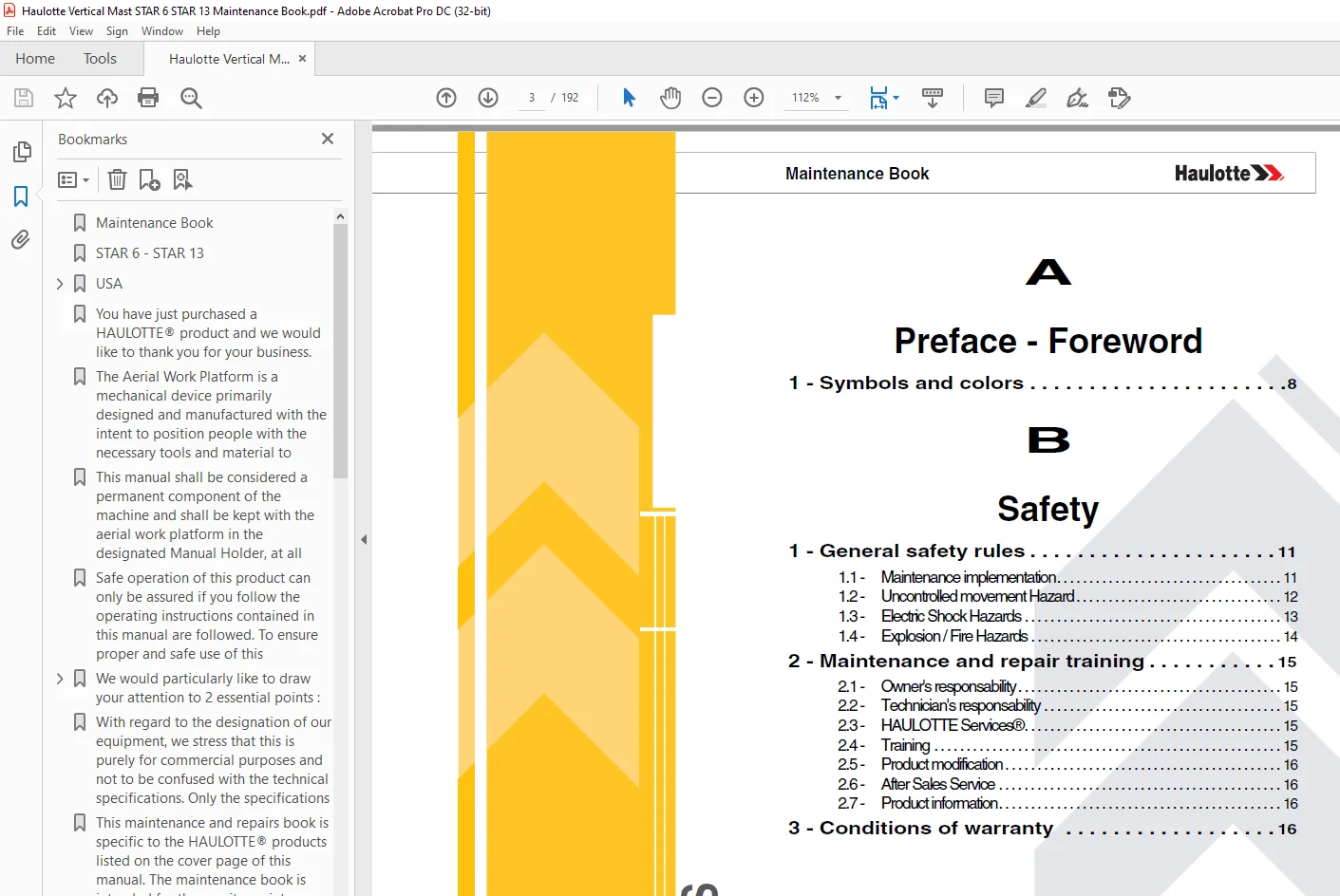
A 3
Preface – Foreword 3
1 – Symbols and colors 8 3
B 3
Safety 3
1 – General safety rules 11 3
11 – Maintenance implementation 11 3
12 – Uncontrolled movement Hazard 12 3
13 – Electric Shock Hazards 13 3
14 – Explosion / Fire Hazards 14 3
2 – Maintenance and repair training 15 3
21 – Owner’s responsability 15 3
22 – Technician’s responsability 15 3
23 – HAULOTTE Services® 15 3
24 – Training 15 3
25 – Product modification 16 3
26 – After Sales Service 16 3
27 – Product information 16 3
3 – Conditions of warranty 16 3
C 4
Familiarization 4
1 – Primary machine components 18 4
11 – Layout 18 4
12 – Maintenance support 22 4
13 – Extension deck (If fitted) 23 4
14 – Ground control box 24 4
141 – Layout 24 4
142 – HAULOTTE Activ’Screen 25 4
1421 – LCD screen 26 4
15 – Platform control box 30 4
151 – Layout 30 4
2 – List of actuators and sensors 32 4
21 – Sensors and actuators 32 4
3 – Consumables 34 4
4 – Ingredient 34 4
41 – Hydraulic oil 34 4
5 – Lubrication diagram 35 4
6 – Greasing points localization 36 4
7 – Machine specifications 36 4
71 – Movement speed 36 4
D 4
Inspection and maintenance schedule 4
1 – Inspection program 37 4
2 – Daily inspection 37 4
3 – Preventive maintenance 38 4
4 – Periodic inspection 42 4
5 – Major inspection 44 4
Machine sheet 5
MS0001 – Structural part inspection 45 5
MS0002 – Pins and bearing inspection 49 5
MS0003 – Cylinder inspection 53 5
MS0004 – Braking test procedure 57 5
MS0005 – Torque Values 59 5
MS0020 – Hoses inspection – Replacement 63 5
MS0059 – Electrical wiring 65 5
MS0086 – Steering cylinder removal 67 5
MS0087 – Pothole cylinder replacement 71 5
MS0088 – Removing the platform 75 5
MS0097 – Calibration steering 81 5
MS0101 – Removing the cylinder 85 5
MS0102 – Tires (Tyres) – Wheel replacement 93 5
MS0103 – Hydraulic oil – Level Replacement 99 5
MS0104 – Lubrication – Steering cylinder – Lift cylinder 101 5
MS0105 – Battery (ies) – Standard machine 103 5
MS0106 – HAULOTTE Activ’Screen 109 5
MS0133 – Universal plug 123 5
MS0154 – Wiring loom 125 5
MS0155 – Remove / Replace mast 133 5
MS0157 – Clearance procedure 141 5
MS0235 – Disassembly – Assembly – Weight sensor (Strain gauge) 143 5
MS0242 – Check of tilt sensor 157 5
MS0245 – Dismantling/Reassembling the Tilt Sensor 163 5
E 6
Trouble shooting and diagram 6
1 – Trouble shooting 171 6
11 – Recommendations 171 6
12 – Description 171 6
13 – Requirements 171 6
14 – Failures list 172 6
2 – Electric diagram 184 6
3 – Hydraulic diagram 190 6
F 6
Records 6
1 – Intervention register 191 6
Preface – Foreword 7
You have just purchased a HAULOTTE® product and we would like to thank you for your business 7
The Aerial Work Platform is a mechanical device primarily designed and manufactured with the intent to position people with the necessary tools and material to overhead elevated temporary workplaces All other uses or alterations/modifications to the 7
This manual shall be considered a permanent component of the machine and shall be kept with the aerial work platform in the designated Manual Holder, at all times 7
Safe operation of this product can only be assured if you follow the operating instructions contained in this manual are followed To ensure proper and safe use of this equipment, it is strongly recommended that only trained and authorized personnel 7
We would particularly like to draw your attention to 2 essential points : 7
• Compliance with safety instruction (machine, use, environment) 7
• Use of the equipment within the performance limits 7
With regard to the designation of our equipment, we stress that this is purely for commercial purposes and not to be confused with the technical specifications Only the specifications in this manual should be used to study the suitability of the equ 7
This maintenance and repairs book is specific to the HAULOTTE® products listed on the cover page of this manual The maintenance book is intended for the on-site maintenance technician 7
It is the on-site maintenance technician’s duty to carry out the regular maintenance work recommended by HAULOTTE Services® 7
This maintenance work is essential for correct machine operation 7
If regular maintenance is not carried out, this may : 7
• Void the warranty 7
• Cause machine malfunction 7
• Reduce machine reliability and shorten its service life 7
• Jeopardize operator safety 7
To ensure that the regular maintenance requirements are fully satisfied, contact HAULOTTE Services® 7
HAULOTTE Services® technicians are specially trained to carry out extensive repairs, interventions or adjustments on the safety systems or elements of HAULOTTE® machines They carry genuine HAULOTTE spare parts and tools as required, and also provi 7
1 – Symbols and colors 8
Symbols and colors are used to alert the operator of safety precautions and/or to highlight important safety information 8
The following safety symbols are used throughout this manual to indicate specific hazards and the hazard severity level when operating or maintaining the Aerial Work Platform 8
Symbol 8
Decals 9
B 11
Safety 11
1 – General safety rules 11
11 – Maintenance implementation 11
Your safety and the safety of the people around are essential 11
Make sure the work area is clean in order to not to pollute the system of the machine 11
Before performing any maintenance interventions, place the machine in maintenance configuration 11
The maintenance stand must be in place before any maintenance operation is begun 11
Placing the machine in maintenance configuration : 11
Putting in use position : 11
Never leave the hydraulic cylinders fully extended before switching off the machine, or when stationary for an extended period of time Keep the elements of the machine in configuration of maintenance thanks to mechanics devices 12
Report that the machine is under maintenance by tagging the platform and ground control boxes 12
Note : 12
12 – Uncontrolled movement Hazard 12
Be aware of uncontrolled movement and always respect the following : 12
13 – Electric Shock Hazards 13
The machine is not electrically insulated and does not provide protection from contact or proximity to electrically charged conductors 13
Always position the lift at a safe distance from electrically charged conductors to ensure that no part of the machine is within an unsafe area 13
Respect the local rules and the minimum safety distance from power lines 13
Minimum safe approach distances 13
Do not operate the machine : 13
Keep away from the machine if it contacts energized power lines Personnel on the ground or in the platform must not touch or operate the machine until energized power lines are shut off 13
In the event of accidental contact with a high voltage line, wait for the power to the line be de-energized before attempting to operate the machine 13
14 – Explosion / Fire Hazards 14
Always wear protective clothing and eye wear when working with batteries and power sources/systems 14
2 – Maintenance and repair training 15
21 – Owner’s responsability 15
The owner (or hirer) has the obligation to inform technician of the instructions contained in the Operator Manual and Maintenance Book 15
The owner (or hirer) has the obligation to renew all manuals or decals that are either missing or in bad condition 15
Additional copies can be ordered from HAULOTTE Services® 15
The owner (or hirer) is responsible for applying the local regulations regarding maintenance of the machine 15
22 – Technician’s responsability 15
The technician must read and understand the contents of this manual, operators manuals and the decals affixed on the machine 15
The technician must inform the owner (or hirer) if the manual or any decals are missing or in poor condition, and of any malfunction of the machine 15
23 – HAULOTTE Services® 15
The HAULOTTE® is at your service in all 5 continents of the world via an extensive network of its own factory trained technicians, who are ready to respond to your every need 15
24 – Training 15
Whether you want to just service your equipment or carry out a complete overhaul, HAULOTTE® can provide you with a structured training program or we can tailor a program to suit your specific requirements or circumstances Training can cover the ge 15
25 – Product modification 16
In a constant effort to improve the quality of machines, HAULOTTE continually monitors technical improvements that enable to develop products with improved safety and greater reliability The target being that HAULOTTE® always work to build confiden 16
These improvements will be shared via the following documents : 16
26 – After Sales Service 16
Our HAULOTTE Services® After Sales Service is at your disposal throughout your machine’s service life to ensure the optimum use of your HAULOTTE product : 16
27 – Product information 16
Without the written permission from Haulotte, modifying a HAULOTTE® product is a Safety concern Any modification may violate Haulotte design parameters, local regulations and industry standards 16
If you desire a modification to the product, submit a request in writing to HAULOTTE 16
With the utmost care to ensure enhanced reliability and greater safety of the HAULOTTE® products, it is pertinent that when a “Service or Safety Bulletin” is issued, action is taken immediately Once the bulletin has been addressed, make sure that t 16
Do not hesitate to contact HAULOTTE Services® , should you have any questions relating to the issued bulletin(s) or with questions on the policy itself 16
3 – Conditions of warranty 16
Our warranty conditions and extension contracts are now available on the websites of our sales network : wwwhaulottecom 16
C 16
Familiarization 16
1 – Primary machine components 18
11 – Layout 18
STAR 6 – STAR 13 18
Universal plug 19
STAR 6 – STAR 13 with platform extension 20
Universal plug 21
12 – Maintenance support 22
The maintenance stand must be in place before any maintenance operation is begun 22
Placing the machine in maintenance configuration : 22
Putting in use position : 22
13 – Extension deck (If fitted) 23
Ensure that gate or sliding bar is in it’s proper closed position 23
Perform these operations on flat, horizontal ground 23
To retract the extension deck, press pedal and pull the extension deck rails inwards to the locked position Release the pedal 23
14 – Ground control box 24
141 – Layout 24
General view 24
Controls and indicators 24
142 – HAULOTTE Activ’Screen 25
Upon starting and during operation of the machine, the LCD screen “Activ’Screen” located on the ground control box displays in real time the machine operating status 25
HAULOTTE Activ’Screen 25
Controls and indicators 25
At startup : 26
At startup with the ground or platform controls selected; system initiates a self check : 26
Alarm status : 28
Alarm status displayed as applicable – samples shown below 28
Tilt : 28
Overload : 28
Low battery : 28
Recharge the batteries : 28
Fully recharge the batteries 28
Low battery water level : 29
Low water tank level : 29
Present fault : 29
15 – Platform control box 30
151 – Layout 30
General view – STAR 6 – STAR 13 30
Controls and indicators 31
2 – List of actuators and sensors 32
21 – Sensors and actuators 32
Sensors and actuators – STAR 6 – STAR 13 32
3 – Consumables 34
4 – Ingredient 34
41 – Hydraulic oil 34
Hydraulic oils must comply with the following requirements : 34
• Antifoam and deaeration 34
• Anti-wear, anti-shear and antioxydant 34
• Rust and corrosion inhibitors (copper) 34
The recommended viscosity grades depending on the environmental conditions are as follows : 34
Biodegradable oils may be used if they comply with the following requirements : 34
5 – Lubrication diagram 35
List of ingredients 35
6 – Greasing points localization 36
• Wheel steering pivots : 2 on the chassis 36
Lubricate the pivots with lead-free grease 36
• Mast lubrication : 36
7 – Machine specifications 36
71 – Movement speed 36
To allow checking operation, refer to the following table about originally time per movement If the values measured by test are not equal to the following : 36
Always check speed movement from the ground control box 36
D 37
Inspection and maintenance schedule 37
1 – Inspection program 37
The machine must be inspected at regular intervals in accordance with the requirements set out in the country of use and at least once a year The purpose of the inspection is to detect any defect which could lead to an accident during routine use of 37
Inspections and maintenance must be carried out by a qualified company or person chosen by the owner of the machine 37
The results of these visits must be recorded in a safety register created by the owner This register as well as the list of competent repair persons must made available to the work inspector, government inspector and company safety committee at any 37
(*) Or according to local regulations 37
2 – Daily inspection 37
The daily inspection must be performed every day, before the start of a new work shift and at every change of user 37
This inspection is performed by and under the responsibility of the user and includes the visual and functional inspection of the machine as well as the testing of its safety systems 37
A description of the daily inspection can be found in the machine’s user manual 37
We recommend these forms to be completed daily and stored to assist with your maintenance schedule 37
3 – Preventive maintenance 38
Maintenance operations must be carried out by a qualified technician chosen by the owner and ensure that the machine operates correctly 38
Severity of operating conditions may require a reduction in time between maintenance periods 38
Maintenance operations performed must be recorded in a register / log book of the machine 38
Symbol meanings 38
Preventive Maintenance Level 1 – First 50H 38
Preventive Maintenance Level 1 – Every 2 weeks 39
Preventive Maintenance Level 1 – Every 6 months or 250H 39
Preventive Maintenance Level 2 – Every 1 year or 500H 40
Preventive Maintenance Level 2 – Every 2 years or 1000H 41
4 – Periodic inspection 42
The Periodic inspection is a thorough inspection of the operation and safety features of the machine This must take place prior to the sale or resale of the machine and every 1 year Local regulations may have specific requirements on frequency, and 42
This intervention must take place after : 42
• Extensive dismantling and reassembly 42
• Repairs involving the machine’s essential components 42
• Any accident causing stress to the machine 42
This inspection is the responsibility of the owner, and must be conducted by a qualified technician 42
Under no circumstances may this inspection replace the control required by local regulations 42
Use the detailed program below 42
5 – Major inspection 44
The inspection is a thorough inspection of the machine to ensure that it is fully functional It must be carried out after 10 years then every 5 years 44
This inspection is the responsibility of the owner and must be carried out by a technician HAULOTTE Services® or an authorized and qualified person 44
In order to carry it out, contact the subsidiary HAULOTTE® or the authorized distributor 44
Machine sheet 44
General data 45
1 – Warning 45
2 – Risk prevention 45
Means of protection to be used when implementing the range 45
3 – You will need 45
4 – Control and maintenance 46
To guarantee the integrity of the machine, it is necessary to carry out periodical controls on the mechanical structure such as defines hereafter 46
41 – Daily inspection 46
All the accessible structural part without disassembling must be subjected to a fast visual inspection 46
If anomalies are noted, according to the list below, a reinforced control will have to be carried out to judge conformity of the part : 46
The list of part to check are define Section Familiarization 46
42 – Major inspection 47
All structural part listed Section Familiarization must be disassembled and all weldsmust be review using non-destructive checks Section D – Inspection and maintenance schedule 47
The criteria quoted above are applicable 47
The main items to be inspected are : 47
Example 47
In the event of suspicion of crack, a cleaning and a sweating are to be carried out to guarantee the integrity of the part before reassembly 47
Check presence and torque of each bolts and screw used to assembly part listed in Section Familiarization Refer to spare part catalog for additional information if needed 47
43 – Functional tests 48
The following tests must be performed periodically Section D – Inspection and maintenance schedule : 48
The following tests must be realized by a qualified staff under secure conditions 48
The results of the tests must be entirely documented 48
To avoid the swing of the machine during the test, it is imperative that a device of reserve (chain, not of anchoring) is used during the test 48
44 – Dynamic tests 48
The machine must be place on level and firm ground 48
With 100% of the maximum allowed load, operate from ground control box (or emergency control box) all the movements ; the platform floor must reach a height of about 1 above the ground 48
The functional tests must show the following facts : 48
Refer to the user manual for the description of the safety device and technical characteristics to be reached 48
45 – Structural test 48
The following test shows that the structure of the machine is in conformity with the safety requirements 48
The machine must be place on level and firm ground 48
With 100% of the maximum allowed load, operate from ground control box (or emergency control box) all the movements ; the platform floor must reach a height of about 1 above the ground : 48
If the difference between two measurements does not exceed 4 cm (1575 in) : the test is validated 48
If the difference between two measurements exceeds 4 cm (1575 in), to contact HAULOTTE Services® or to carry out the additional tests described below MS0003 – § 32 Cylinder inspection 48
General data 49
1 – Warning 49
2 – Risk prevention 49
Means of protection to be used when implementing the range 49
3 – You will need 49
4 – Control and maintenance 50
Inspection of the pins, stop pins, bushings and bearings must be carried out according to the recommendations Section D – Inspection and maintenance schedule : 50
• Fast visual inspection without disassembling Section D – Inspection and maintenance schedule : 50
• Check the presence of the pins and visible stops pins without disassembling 50
• Check the presence of the screws 50
• Check absence of deformations, cracks or breakage of pins and/or stops pins 50
• Check absence of heavy abrasion, wear or oxidation of the pins, stops pins 50
• Reinforced visual inspection with disassembling of certain elements to reach the bushes or bearing Section D – Inspection and maintenance schedule : In addition to the above cited criteria, verify the following : 50
• Check the presence and the position of the bushes and bearings 50
• Check the absence of shaving in periphery of the pins 50
• Check the absence of heavy abrasion, wear or oxidation of the bushes and bearing 50
• Check the absence of deformations, cracks or breakage of the bushes and bearing 50
• Check the absence of radial gap > 0,5 mm (19690 µ in) on the pins 50
• Complete disassembling of the pins, bushes and bearing Section D – Inspection and maintenance schedule : In complement of the inspections above cited, it is necessary to check : 50
• For the stages : 50
• Check the presence of material of friction 50
• For the bearings : 50
• After disassembling, protect the bearing from pollution and shocks 50
• Clean the bearing with a suitable solvent 50
• Check the absence of shaving in the housing of the bearing and/or the bearing 50
• Check the absence of heavy abrasion, wear, oxidation, deformations of the balls (or rollers) and the ball races 50
The periodicity can evolve under the following conditions Section D – Inspection and maintenance schedule : 50
• Abnormal noise during movements of the structure 50
• Prolonged storage of the machine ( 6 months) 50
• Specific storage and use Environment (strong moisture and salinity of the air) 50
5 – Criteria of replacement 50
The pins, stop pins, bushes and bearing must be replaced as soon as one of the anomalies quoted above is noted Bearing and bushes must be imperatively changed at the end of 10 years of use 50
6 – Procedure of reassembly 51
61 – Pins and bushes 51
When reassembling bearings and pins ensure that : 51
Recommended Values 51
62 – Bearings 52
For the reassembly of bearings, respect the following stages : 52
General data 53
1 – Warning 53
2 – Risk prevention 53
Means of protection to be used when implementing the range 53
3 – You will need 53
4 – Control and maintenance 54
41 – Visual inspections 54
The hydraulic actuating cylinders must be subjected to visual inspections periodic all the 250 hours or 6 months such as defined below : 54
42 – Functional tests 54
To guarantee an optimal level of performance and safety, functional tests must be realized all the 250 hours or 6 months 54
The periodicity can evolve under the following conditions : 54
Generic Control : 54
• Lift Arm hydraulic cylinder : Lift the arm to approximately half full height The telescopic boom should be fully extended and in the horizontal position (For machines fitted with) 54
• Boom lifting cylinder or Jib cylinder : Lift the concerned equipment (boom or jib) of approximately half way Extend the telescope to its maximum 54
• Telescoping cylinder : Lift the boom to its maximum angle and telescope approximately 50 cm (1969 in) 54
• If the difference between two measurements does not exceed 4 cm (1575 in) : the test validates correct operation 54
• If the difference between two measurements exceeds 4 cm (1575 in), contact HAULOTTE Services® or carry out the additional tests described below 54
Control cylinder by cylinder : 55
• Attach the body of the comparator on the cylinder rod 55
• The needle of the comparator must be in contact with the end of the casing of the cylinder 55
• The target is to measure the creep of the cylinder rod 55
43 – Major inspection 56
A thorough inspection of the structural parts must be realized all the 5000 h or 10 years with disassembling of the element to check the entirety of the welding Each Cylinder must be disassembled and must be review using non-destructive checks 56
The criteria quoted above are applicable : 56
Check : 56
1 Pipe weld connection 56
2 Rod weld connection 56
3 Ring 56
4 Rod 56
5 Piston 56
General data 57
1 – Warning 57
2 – Risk prevention 57
Means of protection to be used when implementing the range 57
3 – You will need 57
4 – Test procedure 58
The brake system is a significant component of the safety of the machine The following tests must be performed periodically Section D – Inspection and maintenance schedule 58
High speed : 58
• On a flat ground or slightly inclined (always lower than the authorized slope: see plate manufacturer) 58
• Trace on the ground, a line being used as reference mark of stop 58
• Roll moving front until reaching maximum speed : 58
• Between 3 km/h (19 mph) and 6,5 km/h (4,039 mph) according to the machines 58
• Release the manipulator as soon as the wheels axles are on the level of the traced reference mark 58
• Stopped machine, measure the distance between the wheel axles and traced reference mark on the ground : 58
• If the distance lies between 02 m (0ft 8in) and 2,7 m (8 ft 11 in), the test is validated 58
• If not, Contact HAULOTTE Services® to repair the system 58
General data 59
1 – Metric torque chart 59
For screws HAULOTTE®, use columns ( A ), ( B ) and ( C ) : 59
• Screw ( 1 ) grey dull dry, use colums ( A ) 59
• Screw ( 1 ) grey dull greasy, use column ( B ) 59
• Screw ( 2 ) yellow dry, use column ( C ) 59
• Screw ( 2 ) yellow greasy, use column ( B ) 59
• Screw ( 3 ) grey bright dry, use column C 59
• Screw ( 3 ) grey bright greasy, use column ( B ) 59
2 – SAE fastener torque chart 60
3 – Hydraulic couplings and hoses tightening torque charts 61
Hydraulic fitting torque (Tolerance = 0 / +10%) 61
Hydraulic hose torque (Minimum / Maximum) 62
4 – STAR 6 – STAR 13 62
Hydraulics 63
1 – You will need 63
2 – Control and inspections 63
The state of hoses devices plays a significant role in the safety of the machines 63
Section D – Inspection and maintenance schedule : 63
• Check the absence of leakage to the junctions of the hoses 63
• Check that all the hoses are correctly tightened 63
• Check the absence of tear and crack of the external hoses 63
• Check that the shielding of the hose is not apparent 63
• Check the absence of chemical aggression of the membrane of the hose 63
If anomalies are noted, it is necessary to replace the elements by respecting the following recommendations 63
3 – Hoses Disassembling 63
For safety reasons, respect imperatively the following conditions of disassembling : 63
• Fold the machine on a flat and released ground : 63
• The machine is not in slope 63
• The boom is horizontal 63
• Put the turret (if equipped) in the axis 63
• Carry out a beaconing of the sector (maximum risk zone = machine height) 63
• Locate the hoses and their connections points to guarantee the good performance of the machine after intervention 63
• Locate the hoses course to facilitate the reassembly 63
To recover oil, use an oils container in order not to pollute the environment 63
After disassembling : 63
• Close the hose openings and the hydraulic components to avoid the pollution of the hydraulic system 63
• Check the cleanliness of the hoses and the hydraulic components : 63
• Absence of plastic, rubber or metal shaving 63
• If necessary, purge and clean the circuit (tank included) 63
4 – Hoses Reassembly 64
For safety reasons, respect imperatively the following conditions of reassembly : 64
• Using the reference marks carried out previously; carry out the courses of hoses 64
• During the fixing of the hoses, respect the tightening torques below 64
Tightening torque table 64
Once all the hoses are correctly tight : 64
• Put the machine in operational configuration 64
• Carry out some movements implementing the hoses concerned in order to purge the hydraulic system 64
• Check the absence of leakage 64
• Control the level of hydraulic oil tank 64
• Check the pressures 64
Electric 65
1 – You will need 65
Maintaining electrical wiring in good condition is essential to safe operation and good machine performance Failure to find and replace burnt, chafed, corroded or pinched wires could result in unsafe operating conditions and may cause component damage 65
• Open the side covers 65
• Inspect the following areas for burnt, chafed, corroded and loose wires : 65
• Cable carrier cat track 65
• Engine wiring harness 65
• Hydraulic manifold wiring 65
• Gear ring rotation block 65
• Mast lowering emergency block 65
Chassis 67
1 – You will need 67
2 – Level of knowledge required 67
It is important that the person performing the work on the machine knows all the relative safety information contained in the instruction manual 67
3 – Safety instructions 67
4 – Preliminary operation 68
The operations of disassembling if they exist should be carried out only on the installations completely disconnected and must be entrusted only to people having the necessary technical training 68
Respect, in addition to the instructions appearing in the present instructions, the legal tendencies generally applicable for safety accident prevention 68
All the precautions must be done in work before intervening on and near the machine 68
After completion of work, all the covers and safety devices must be positioned back completely and operational 68
5 – Removal 68
• Raise the telescoping mast upto 1,20 m(3 ft11 in) (Tube 1) 68
• Insert the safety prop ( 1 ) in the hole to lock the mast 68
• Steer the machine so the wheels are straight ahead 68
• Remove the central cover 68
• Remove the circlip from the rod end of the cylinder (fixed to the pivot), the washer and extract the pin 69
• Turn the steering towards the left side, to retract the steering cylinder 69
• Disconnect the 2 hoses from the cylinder, fit plugs and caps to the hose and cylinder 69
• Remove the circlip from the bore end (front left) of the cylinder, the washer and extract the pin 69
• Remove the cylinder 69
6 – Reinstall 70
• Install the bore end (front side) pivot pin, refit the washer and circlip 70
• Re-connect the hoses to the cylinder 70
• Operate the steering towards the right side, to align the cylinder with the pivot 70
• If you cannot align easliy with the pump, turn the wheels slightly by kicking them ir tapping with a soft hammer 70
• Install the rod end pin of the cylinder (fixed to the pivot), refit the washer and circlip 70
• Refit the top cover plate 70
• Remove the safety support and lower the mast 70
7 – Checks 70
• Switch the machine on 70
• Engage drive and steering Check there are no leaks or abnormal noises 70
Chassis 71
1 – You will need 71
2 – Level of knowledge required 71
It is important that the person performing the work on the machine knows all the relative safety information contained in the instruction manual 71
3 – Safety instructions 71
4 – Preliminary operation 72
The operations of disassembling if they exist should be carried out only on the installations completely disconnected and must be entrusted only to people having the necessary technical training 72
Respect, in addition to the instructions appearing in the present instructions, the legal tendencies generally applicable for safety accident prevention 72
All the precautions must be done in work before intervening on and near the machine 72
After completion of work, all the covers and safety devices must be positioned back completely and operational 72
5 – Removal 72
Drive then lift the machine just for a brief moment, to put the potholes in a “mid way” position, between fully retracted and fully extended This is to remove any pressure from the pivot pins and make removal easier 72
• Open the battery trays on either side of the machine 72
• Remove the circlips and washers from the pivot pins at both ends and slide the cylinder off the pins 72
• Disconnect the hydraulic hoses, plug and cap the hoses and fittings 72
6 – Reinstall 73
• Reverse the above procedure 73
Platform 75
1 – You will need 75
2 – Level of knowledge required 75
It is important that the person performing the work on the machine knows all the relative safety information contained in the instruction manual 75
3 – Safety instructions 75
4 – Preliminary operation 76
The operations of disassembling if they exist should be carried out only on the installations completely disconnected and must be entrusted only to people having the necessary technical training 76
Respect, in addition to the instructions appearing in the present instructions, the legal tendencies generally applicable for safety accident prevention 76
All the precautions must be done in work before intervening on and near the machine 76
After completion of work, all the covers and safety devices must be positioned back completely and operational 76
5 – Removal 76
• Remove the front kick panel 76
• Remove covers around the mast : Drill out the rivits using a drill 5 mm 76
• Remove the manual box : Drill out the rivits using a drill 5 mm 76
• Support the platform on slings : 77
2 x 1,5 m on the front, top rail, and 2 x 2 m on the rear mid rail 77
• Unscrew the 2 support fastening screws on the platform 77
• Remove the 2 fastening screws from the sheet metal, located on each side of the mast 77
• Remove the protective sheet metal from the sensor 77
• Raise the platform using the bridge in order to insert a shim to secure the assembly 78
• Switch off the ignition and remove the ignition key 78
• Lightly tension the strap with the bridge 78
• Remove the 2 gauges to take out the mast 78
• Remove the 8 screws from the gauge starting with those on top then those on the bottom 78
• Lightly unscrew the upper fastening screws from the opposite gauge 78
• Disconnect the connector from each gauge 78
• Raise the bridge approximately 1 cm in order to release the gauge 79
• Unscrew the 4 bolts around the mast with a key and socket 24 mm 79
• Turn the wheels to the left side 79
Turn to full stop to unscrew the bolts on the (right) platform side, using a socket and 30 cm (12”) extension and socket 79
• Turn slightly back form full left, to access the bolts on the left (non platform) side use a 30 cm (12”) extension on the forward bolt, and a shorter 6 cm (6”) extension for the rear bolt, to avoid the wheel pivot 79
• Remove the control box 80
• Lift the platform untill the mid handrail can pass over the mast 80
• Place the platform on a pallet 80
6 – Reinstall 80
• Position the new platform; the front sill panel must be reassembled then referred directly to : MS0235 – Dismantling/Reassembling the strain gauge 80
Chassis 81
1 – You will need 81
2 – Level of knowledge required 81
The use of this card implies that its user is trained on this kind of machine and that this training was delivered by Haulotte or an authorised representative 81
It is important that the person performing the work on the machine knows all the relative safety information contained in the instruction manual 81
3 – Preliminary operation 81
The operations of disassembling if they exist should be carried out only on the installations completely disconnected and must be entrusted only to people having the necessary technical training 81
Respect, in addition to the instructions appearing in the present instructions, the legal tendencies generally applicable for safety accident prevention 81
All the precautions must be done in work before intervening on and near the machine 81
After completion of work, all the covers and safety devices must be positioned back completely and operational 81
• The worker must make sure to have the EPI (Personal Protective Equipment) suited to the work and to the environment’s specific conditions in which the equipment is located (see safety information specific to the work site 81
• Position the machine on a flat and firm surface, clear of obstructions (beware of power lines) 81
• Mark out the work area 81
• Switch off the ignition and remove the ignition key 81
• Software version : 4001057180 – V303 or above 81
• Put a “DO NOT USE” decal near the start/stop button to inform personnel that work is currently in progress on the equipment 81
• Beware of the risk of burns; the hydraulic system operates at high temperatures 81
• The pressure in the hydraulic system is very important It can cause accidents Relieve the pressure before beginning any work and never search for oil leaks using your hands 81
• Engine exhaust gases contain harmful products of combustion Always start and run the engine in a well-ventilated area In a closed room, ensure the exhaust gases are evacuated to the outside 81
4 – Steering calibration procedure 82
In the ACTIV’Screen (or using HaulotteDiag) navigate to the calibration menu and enter Steering calibration 82
Sensor SR150 82
Sensor SR150_1 83
5 – Checks 84
Turn on the machine and test the steer function- the pump motor should stop when the steering is at mechanical limit and the steering switch is held on : 84
Sensor SR150_1 84
Lift cylinder 85
1 – You will need 85
2 – Level of knowledge required 85
It is important that the person performing the work on the machine knows all the relative safety information contained in the instruction manual 85
3 – Safety instructions 85
4 – Preliminary operation 86
The operations of disassembling if they exist should be carried out only on the installations completely disconnected and must be entrusted only to people having the necessary technical training 86
Respect, in addition to the instructions appearing in the present instructions, the legal tendencies generally applicable for safety accident prevention 86
All the precautions must be done in work before intervening on and near the machine 86
After completion of work, all the covers and safety devices must be positioned back completely and operational 86
Remove the platform : See : MS0088 – Removing the platform 86
5 – Removal 86
• Remove cover from top of mast 86
• Remove cover from chassis 86
• Unscrew the fixing plate for the cable clamp at the top of the mast 87
• Pass the wiring loom down the interior of the mast 87
• Remove the keeper bolt from the up of the mast out section 87
• Attach sling to outer section and raise about 1 m(3 ft3 in) 88
• Mark the pads before removing, and note the shims (if used) and type of pad (white or black) for each pad 89
• Lift the outer mast assembly clear and place on the ground 89
• Attach 2 slings to the inner mast section on the lifting eyes 90
• In the chassis, cut the cable ties holding the wiring loom for the mast Disconnect the mast wiring loom and pull it free under the machine 90
• Reach under the mast and you will be able to feel the coil on the lift cylinder Disconnect the plug on the cylinder and pull the coil wiring free 90
• Disconect the hydraulic hose, at the motor pump group (this is easier to access) Plug and cap the hose and fittings 90
• Unscrew the 4 bolts that hold the mast to the ground 91
• Begin to lift the mast, just to it is a few millimeters off the base Push towards the front, then carefully pull the hydraulic hose free 91
• Lift the mast free, and pose carefully on the ground 92
Once on the ground, the mast can be slinged horizontally to place easily on supports, without a chance of the mast sliding Place the mast on tresteles, with the cylinder to the left side, and wiring loom to thze right side (when viewed from the bott 92
• Unbolt the angle bracket that holds the cylinder to the lowest section 92
• Turn the mast on it’s side to remove the keeper bolts from each inner mast stage With the mast on it’s side the bolt for the inner section to stay extended 92
• After the cylinders are free, turn the mast again to the vertical side (This is important, if not the cylinder could “open”) 92
• With one person guiding the top of the cylinders, and a second pulling on the bottom, slowly pull the cylinder out of the mast 92
• Attach the sling on the cylinder at approximately 78 cm from the foot of the cylinder, to be at the balance point 92
• Place the cylinder on the trestles 92
6 – Reinstall 92
• Reverse the above procedure 92
Chassis 93
1 – You will need 93
2 – Preliminary operation 93
For safety reasons, imperatively respect the following stages during the tests : 93
• To set up a beaconing of safety around the test area 93
• Put the machine in stowed position 93
The operations of disassembling if they exist should be carried out only on the installations completely disconnected and must be entrusted only to people having the necessary technical training 93
Respect, in addition to the instructions appearing in the present instructions, the legal tendencies generally applicable for safety accident prevention 93
All the precautions must be done in work before intervening on and near the machine 93
After completion of work, all the covers and safety devices must be positioned back completely and operational 93
3 – Technical specifications 93
4 – Wheel and tires/tyres inspections 94
Replace the wheels and the tires if any of the following conditions exist : 94
• Presence of cracks, damage, deformation or other faults on the hub 94
• Damage to the tire : 94
• Cut or hole > 3 cm (2 in) in the rubber side wall 94
• Blister or pronounced lump on the external and lateral wall 94
• Damaged wheel stud 94
• Damage or wear on the side wall to the extent that the reinforcing wire is visible 94
• Consistent wear of the ground contact surface greater than 25% 94
• Check that the pin 2352101250 is present and in good condition – Replace as necessary 94
5 – Procedure of replacement 95
• Slightly lift the machine using a forklift 95
• Place a wooden spacer under the frame to support the machine after lifting off the ground 95
• Remove the pin ( 1 ), the wheel nut ( 2 ) and the flat washer(3) 95
• Remove the wheel 95
Reassembly of the wheel 96
• Use a new flat washer (2700500110) 97
• Use a new nut (4000503700) 97
1 Check that the shaft key is well positioned in the motor shaft 97
2 Mount the wheel on the motor shaft 97
3 Install the washer first then the nut 97
4 Tighten the wheel nut to the recommended torque : 250 Nm (184 ftlbs) 97
5 Add tightening until a groove of the nut is in coincidence with one hole of the shaft of the motoreducer 97
6 Insert the pin (2352101250) into its seating 97
7 Bend over the cotter pin legs to secure the nut 97
Hydraulics 99
1 – You will need 99
2 – Preliminary operation 99
For safety reasons, imperatively respect the following stages during the tests : 99
• To set up a beaconing of safety around the test area 99
• Put the machine in stowed position 99
• Use safety straps 99
The operations of disassembling if they exist should be carried out only on the installations completely disconnected and must be entrusted only to people having the necessary technical training 99
Respect, in addition to the instructions appearing in the present instructions, the legal tendencies generally applicable for safety accident prevention 99
All the precautions must be done in work before intervening on and near the machine 99
After completion of work, all the covers and safety devices must be positioned back completely and operational 99
3 – Level control 99
Each day before use, check the hydraulic oil level to ensure safety operation 99
The oil level (1) must be between the upper and lower markers 99
Top up the oil level, if necessary : 99
1 Loosen and remove the tank cap (2) 99
2 Top up the oil level 99
3 Refit and tighten the tank cap (2) 99
4 – Replacement of hydraulic oil100
The state of cleanliness of the oil filter cartouche is another indicator of purging of the system :100
• Dismount the cartouche of the oil filter100
• Check the absence of rubber, plastic or metal shaving100
41 – Consumable100
Use only oils whose features correspond to HAULOTTE® recommendations (Section C – Familiarization – Consumable) or contact HAULOTTE Services®100
Not mix two different characteristics oils If necessary, purge and clean the circuit100
42 – Filling100
To fill the system correctly; respect the following stages :100
Chassis – Mast101
1 – You will need101
2 – Preliminary operation101
The operations of disassembling if they exist should be carried out only on the installations completely disconnected and must be entrusted only to people having the necessary technical training101
Respect, in addition to the instructions appearing in the present instructions, the legal tendencies generally applicable for safety accident prevention101
All the precautions must be done in work before intervening on and near the machine101
After completion of work, all the covers and safety devices must be positioned back completely and operational101
3 – Lubrication101
Steering cylinder101
In order to maintain the lifting cylinder in good condition and avoid any internal or external corrosion during prolonged storage (inside or outside), proceed as follows :101
• Wheels aligned101
Lift cylinder102
In order to maintain the lifting cylinder in good condition and avoid any internal or external corrosion during prolonged storage (inside or outside), proceed as follows :102
• Store the machine with retracted mast102
Electric103
1 – You will need103
2 – Control103
1 Open battery compartments103
2 Lift the cover off the top of the battery103
The level of electrolyte in the battery must be approx 0,01 m(0 ft39 in) above the plates103
3 – Filling-up104
Lift the cover off the top of the battery104
If the level of electrolyte is below the level of the plates :104
1 Top up with distilled water104
2 Re-install the cover104
4 – Battery charge104
Battery charger status104
Ground control box :104
The indicator (90) indicates charge status104
• Green indicator : Battery charged 100 %104
• Yellow LED : Battery charged 80 %104
• Red LED : Battery in initial charging phase104
Platform control box :104
The indicator (135) indicates charge status104
• Battery charged :104
• Flashing : Batteries have 40% charge left :104
• Constantly on : Batteries have only 20% charge left :104
When should the batteries be charged? :105
• Never discharge the batteries to more than 80 % of their capacity in 5 h (hours)105
• When the batteries are discharged to between 35 % and 80 % of their nominal capacity105
• If installing new batteries, recharge them after 3 or 4 hours of use 3 to 5 times105
• After a long period of non-use105
• Never leave the batteries discharged105
• Do not put off recharging the batteries in cold weather as the electrolyte may freeze105
How to charge the batteries ? :105
• Use the machine’s on-board charger The charger has a charge rate compatible to the battery capacity105
• Ensure that the mains supply is compatible to the charger’s consumption105
• Top up the batteries with distilled water to the minimum electrolyte level if any of the elements are below this minimum level105
• Work in a clean and well-ventilated area away from naked flames105
Start-up is automatic as soon as the mains connection is established The charger is fitted with a LED indicator placed near the special holding frame :106
• Green indicator : Battery charged 100 %106
• Yellow LED : Battery charged 80 %106
• Red LED : Charger in the intitial charge phase106
When there is a fault, the LED indicator flashes in various colours depending on the type of alarm :106
In case of an alarm, the charger stops supplying power106
During charging :106
• The machine’s electric system is automatically deactivated while the external power supply is connected to the machine106
• Ensure that the battery are at a temperature not exceeding 45 °C(113 °F) (be careful in summer or in places with a high ambient temperature)106
• Do not remove or open the caps on the elements106
Charge interruption :106
• To turn off the charger, disconnect it from the mains supply106
• Should the machine need to be operated during a charging cycle, first diconnect the charger This may reduce the life span of the batteries Re-connect the charger once the operation is over106
After charging :106
• Top up the electrolyte level, if necessary106
• Avoid overflowing106
• Wash the top of the batteries without removing the caps106
• Dry with compressed air or clean cloths106
• Oil the terminals106
Battery charge status according to density and temperature107
Loss of capacity during prolonged storage108
Electrolyte freezing point according to the density of the acid and state of charge108
Ground control box109
1 – You will need109
Upon starting and during operation of the machine, the LCD screen “Activ’Screen” located on the ground control box displays in real time the machine operating status109
2 – Simplified menus109
3 – Detailed menus111
31 – Screen access code settings121
311 – Screen 0d121
This screen allows the access to the following screens When this state is active, there is no scrolling with other possible states Only the “screen saver” is active In this screen, it is possible to enter a level code from 1 to 3 :121
Screen_Acces_code Username :121
Screen_Acces_level_x Username :122
Screen_Bad_code Username :122
Turntable123
1 – You will need123
2 – Procedure123
Step 1 :123
• Disconnect the plug 2123
• Remove the caps on the plug123
Step 2 :123
• Pick up the pins in the plastic bag123
• Strip the wires of the tracker123
• Crimp the wires with the pins with a crimping clamp123
Step 3 :124
• Take the wedgelock off the plug124
• Thread the wires in the positions regarding the information124
Step 4 :124
• Put the wedgelock back on the plug to fix the pins124
Step 5 :124
• Reconnect the plugs124
• Mount the tracker124
• The tracking device is operational124
Mast125
1 – You will need125
2 – Level of knowledge required125
3 – Safety instructions125
4 – Preliminary operation126
The operations of disassembling if they exist should be carried out only on the installations completely disconnected and must be entrusted only to people having the necessary technical training126
Respect, in addition to the instructions appearing in the present instructions, the legal tendencies generally applicable for safety accident prevention126
All the precautions must be done in work before intervening on and near the machine126
After completion of work, all the covers and safety devices must be positioned back completely and operational126
Remove the platform : See : MS0088 – Removing the platform126
5 – Removal126
• Remove cover from top of mast126
• Remove cover from chassis126
• Unscrew the fixing plate for the cable clamp at the top of the mast127
• Pass the wiring loom down the interior of the mast127
• Remove the keeper bolt from the up of the mast out section127
• Attach sling to outer section and raise about 1 m(3 ft3 in)128
• Mark the pads before removing, and note the shims (if used) and type of pad (white or black) for each pad129
• Lift the outer mast assembly clear and place on the ground129
• Attach 2 slings to the inner mast section on the lifting eyes130
• In the chassis, cut the cable ties holding the wiring loom for the mast Disconnect the mast wiring loom and pull it free under the machine130
• Reach under the mast and you will be able to feel the coil on the lift cylinder Disconnect the plug on the cylinder and pull the coil wiring free130
• Disconect the hydraulic hose, at the motor pump group (this is easier to access) Plug and cap the hose and fittings130
• Unscrew the 4 bolts that hold the mast to the ground131
• Begin to lift the mast, just to it is a few millimeters off the base Push towards the front, then carefully pull the hydraulic hose free131
• Lift the mast free, and pose carefully on the ground131
• Once on the ground, the mast can be slinged horizontally to place easily on supports, without a chance of the mast sliding132
• Unbolt the fixation from the bottom of the cable mast sliding132
• Fix a cord to the bottom of the spiral cable and pull it through the top132
6 – Reinstall132
• Reverse the above procedure132
7 – Checks132
• Switch the machine on132
• Check the parameters132
• Check settings132
• Test all the movements from the platform and ground control boxes132
Mast133
1 – You will need133
2 – Level of knowledge required133
3 – Safety instructions133
4 – Preliminary operation134
The operations of disassembling if they exist should be carried out only on the installations completely disconnected and must be entrusted only to people having the necessary technical training134
Respect, in addition to the instructions appearing in the present instructions, the legal tendencies generally applicable for safety accident prevention134
All the precautions must be done in work before intervening on and near the machine134
After completion of work, all the covers and safety devices must be positioned back completely and operational134
Remove the platform : See : MS0088 – Removing the platform134
5 – Removal134
• Remove cover from top of mast134
• Unscrew the fixing plate for the cable clamp at the top of the mast134
• Pass the wiring loom down the interior of the mast135
• Remove the keeper bolt from the up of the mast out section135
• Attach sling to outer section and raise about 1 m(3 ft3 in)135
• Mark the pads before removing, and note the shims (if used) and type of pad (white or black) for each pad136
• Lift the outer mast assembly clear and place on the ground136
• Remove the keeper pin for the second mast section137
• Attach the sling to the cylinder support and lift the mast section to about 1 m(3 ft3 in)137
• Mark the pads before removing and note the shims (if used) for each pad137
• Lift the second section free, paying attention to the cable for the upper controls, which needs to pass through the middle137
• Remove the keeper pin for the third mast section138
• Attach the sling to the cylinder support and lift the mast section to about 1 m(3 ft3 in)138
• Mark the pads before removing, and note the shims (if used) and type of pad (white or black) for each pad138
• Lift the third section free, paying attention to the cable for the upper controls, which needs to pass through the middle139
• To replace the outer wear pads on the inner (fourth) section, mark each type of pad (white or black) and note the shims (if used), as you will need to re-fit these the same on re-assembly139
The access is somewhat limited :139
• For the pad fixed near the harness, you must push the wiring loom down the mast section to have access139
• For the pad front left (next to the wiring harness) you will need to use a standard allen key139
• For the pad rear left, the access to the lower screw is restricted, a small ratchet and extension is required139
6 – Reinstall140
• Before lifting the third section into position, pass a rope down the inside This is to aid in pulling the harness through140
• Grease the pads well before mounting140
• Install all the pads with their shims (if fitted) before tightening Use loctite “Red” on the screws to secure them140
• Place the third section over the fourth inner section, and pull the electrical cable so there is no slack (if not you risk to have the cable get stuck)140
• Lower the third mast section to about 1 m(3 ft3 in)140
• Install the inner wear pads in the same position, and with the same spacers, as noted in dissasembly140
• Lower the section down, untill it is almost at the bottom Take care to align the cylinder into the mount Lower the mast section, remove the strap, and fit the keeper bolt140
7 – Checks140
• Switch the machine on140
• Check the parameters140
• Check settings140
• Test all the movements from the platform and ground control boxes140
• Check no alarms are present140
• Repeat for the other sections the same140
• Carry out the calibration procedure (Refer to MS0235 – Dismantling/Reassembling the strain gauge)140
Mast141
1 – You will need141
2 – Level of knowledge required141
It is important that the person performing the work on the machine knows all the relative safety information contained in the instruction manual141
3 – Safety instructions141
4 – Procedure142
Rules regarding the number of pade spacer to put :142
• The side clearance adjustment is made by the pad chock :142
• Maximum side clearance between the pads and the next boom : 1 mm142
• The pad spacers quantity must be approximately the same on each sides of the boom142
• The longitudinal clearance adjustment is made by the choice between the thin or the thick pad :142
• Put the thicker one142
The pads must be attached with CHC M6X10 screws and M6 locknuts142
Chassis143
1 – Warning143
2 – Risk prevention143
Means of protection to be used when implementing the range143
3 – You will need143
4 – Dis-assembly144
• Position the machine on a flat and firm surface, clear of obstructions (beware of power lines)144
• The machine must be fully stowed (arm, boom, jib, telescope) with the turntable aligned144
• Mark out the work area (barriers, cones, marking tape)144
• Restrict access to the area (restricted access sign)144
• Place a do not operate tag at the start/stop switch location to inform personnel that the equipment is being worked on144
• Sling the platform using two straps and tie it to the crane144
• Put the bridge under slight strain144
• Unscrew the 2 support fastening screws on the platform145
• Remove the 2 fastening screws from the sheet metal, located on each side of the mast145
• Remove the protective sheet metal from the sensor145
• Raise the platform using the bridge in order to insert a shim to secure the assembly145
• Switch off the ignition and remove the ignition key146
• Lightly tension the strap with the bridge146
• Remove the 4 screws from the gauge starting with those on top then those on the bottom146
• Lightly unscrew the upper fastening screws from the opposite gauge146
• Disconnect the connector from the gauge146
• Raise the bridge approximately 1 cm in order to release the gauge146
• Clean the bearing surface of the gauge as well as the mounting holes147
5 – Reassembly148
• Fit a new gauge148
• Gently screw the bottom fastening screws148
• Gently screw the the top fastening screws148
• Ensure that the front sill panel is present and correctly tightened before tightening the sensor on the mast149
• Position (without tightening) the 2 fastening screws of the guard rail on the mast149
• Tighten the 4 bottom screws to a torque of 120 Nm ( 2 left then 2 on the right)149
• Tighten the 4 top screws to a torque of 120 Nm ( 2 left then 2 on the right)149
• Tighten the 4 bottom screws to a torque of 190 Nm ( 2 left then 2 on the right)149
• Tighten the 4 top screws to a torque of 190 Nm ( 2 left then 2 on the right)149
• Reconnect the gauge150
• Reinstall the fastening plate of the gauge150
• Reinstall the fastening plate of the railing on the mast150
• Tighten the 2 M8x12 screws of the railing on the tube according to the standard tightening torque (22 Nm)150
• Put the bridge under tension again150
• Raise the platform150
• Remove the shim150
• Position – 230 kg in the centre of the platform against the mast150
• Lift twice the platform to approximately 50 cm in height (SQ721 = 0)150
• Carry out a full load lift/lower manoeuvre from the ground control box before calibrating the ground control box150
• Then remove the 230 kg load for empty calibration150
• Carry out the calibration procedure (Refer to the illustrations below)150
• On the Activ’Screen screen, enter the level 2 access code :150
• Menu : Machine settings151
• Menu : Calibration151
• OFFSET menu of the load management system with platform empty152
• Gain of Load Management System menu with fixed weight of 230 kg154
• Position – 230 kg in the centre of the platform against the mast154
• Complete calibration156
6 – Checks156
• Put 240 kg on the platform, lift the load and ensure that the lifting is well cut off by the weighing system156
Chassis157
1 – Warning157
2 – Risk prevention157
Means of protection to be used when implementing the range157
3 – You will need157
4 – Check of tilt sensor158
• Put the machine in stowed position158
• Position the machine on an incline that is greater than the maximum permitted incline158
• Check that the tilt indicator is on ( 27)158
• Fit the platform and ensure that movement is off and the buzzer is triggered158
• Position the machine on a flat and firm surface, clear of obstructions (beware of power lines)158
• Mark out the work area (barriers, cones, marking tape)158
• Restrict access to the area (restricted access sign)158
• Switch off the ignition and remove the ignition key158
• Place a do not operate tag at the start/stop switch location to inform personnel that the equipment is being worked on158
• Position the electronic level under the chassis and note the values displayed on the X and Y axis159
• Check the X and Y axis :159
Axis X159
Axis Y159
• Turn on ignition key and start up engine159
• Compare the tilt values X and Y of the machine with an electronic level to those displayed on the screen Activ’ Screen159
• In the main menu select : Machine settings > Calibration > Tilt > Check of tilt sensor :160
• If the gap is > 0,5°, carry out a new calibration (Refer to MS0245 – Dismantling/Reassembling the Tilt Sensor)160
Chassis163
1 – Warning163
2 – Risk prevention163
Means of protection to be used when implementing the range163
3 – You will need163
4 – Dis-assembly164
• Position the machine on a flat and firm surface, clear of obstructions (beware of power lines)164
• Mark out the work area (barriers, cones, marking tape)164
• Restrict access to the area (restricted access sign)164
• Switch off the ignition and remove the ignition key164
• Place a do not operate tag at the start/stop switch location to inform personnel that the equipment is being worked on164
• Cut the COLSON tie holding the tilt cable164
• Unscrew the 2 fixing screws (1)164
5 – Reassembly165
• Reverse the above procedure165
• Tighten the brake nuts to a torque of 10 Nm then mark the screws with the sealing165
• Fasten the tilt cable with a COLSON tie onto the sleeve clamp165
• Carry out the calibration procedure(Refer to the illustrations below)165
6 – Calibration165
• On the Activ’Screen screen, enter the level 2 access code165
• Menu : Machine settings165
• Menu : Calibration166
• Menu : Slope sensor on flat ground166
7 – Additional operations168
• Position the machine on an incline that is greater than the maximum permitted incline168
• Fit the platform and ensure that movement is off and the buzzer is triggered168
• Check that the tilt values in X and Y displayed on the screen Activ’ Screen are identical to the current machine values (check using an electronic level on the chassis) +/-03°168
The position of the electronic tilt :168
Axis X168
Axis Y168
• Procedure to verify the tilt angle using the screen Activ’ Screen :169
• In the main menu select : Machine settings > Calibration > Tilt > Check of tilt sensor169
E169
Trouble shooting and diagram170
1 – Trouble shooting171
11 – Recommendations171
If a malfunction occurs, check the following points :171
If the malfunction persists, consult the troubleshooting table to identify the problem171
IF you cannot identify the problem, contact HAULOTTE Services®171
12 – Description171
The FAILURES function describes the requirements relative to failures : monitoring, information recording, information reading171
13 – Requirements171
14 – Failures list172
2 – Electric diagram184
Electricity part 4001016950 A – folio 01184
Variable speed drive part 4001016950 A – folio 02185
Variable speed drive part 4001016950 A – folio 03186
Cage part 4001016950 A – folio 04187
Option – Weighing system 4001016950 A – folio 05188
Option – Lithium battery 4001016950 A – folio 06189
3 – Hydraulic diagram190
STAR 6 – STAR 13 – 4000353410 C190
F190
Records191
1 – Intervention register191
The intervention register keeps a record of maintenance and repair work carried out inside or outside the maintenance programme191
IMAGES PREVIEW OF THE MANUAL:
S.M 07/24