Hill-Rom V-CUE Dynamic Air Therapy Unit Service Manual – PDF
Original price was: $95.00.$30.95Current price is: $30.95.
Official Hill-Rom V-CUE Dynamic Air Therapy Unit service manual (man146rb, Rev B, 2000). Covers complete troubleshooting procedures, theory of operation, removal & replacement of all components, illustrated parts list, general maintenance, and software diagnostics. Models P540A series (120V & 230V). Essential reference for facility biomedical technicians servicing Hill-Rom dynamic air therapy mattress systems. Instant PDF download – 223 pages of factory-level clinical equipment documentation.
Description
Hill-Rom V-CUE Dynamic Air Therapy Unit Service Manual Repair & Parts PDF DOWNLOAD
Description
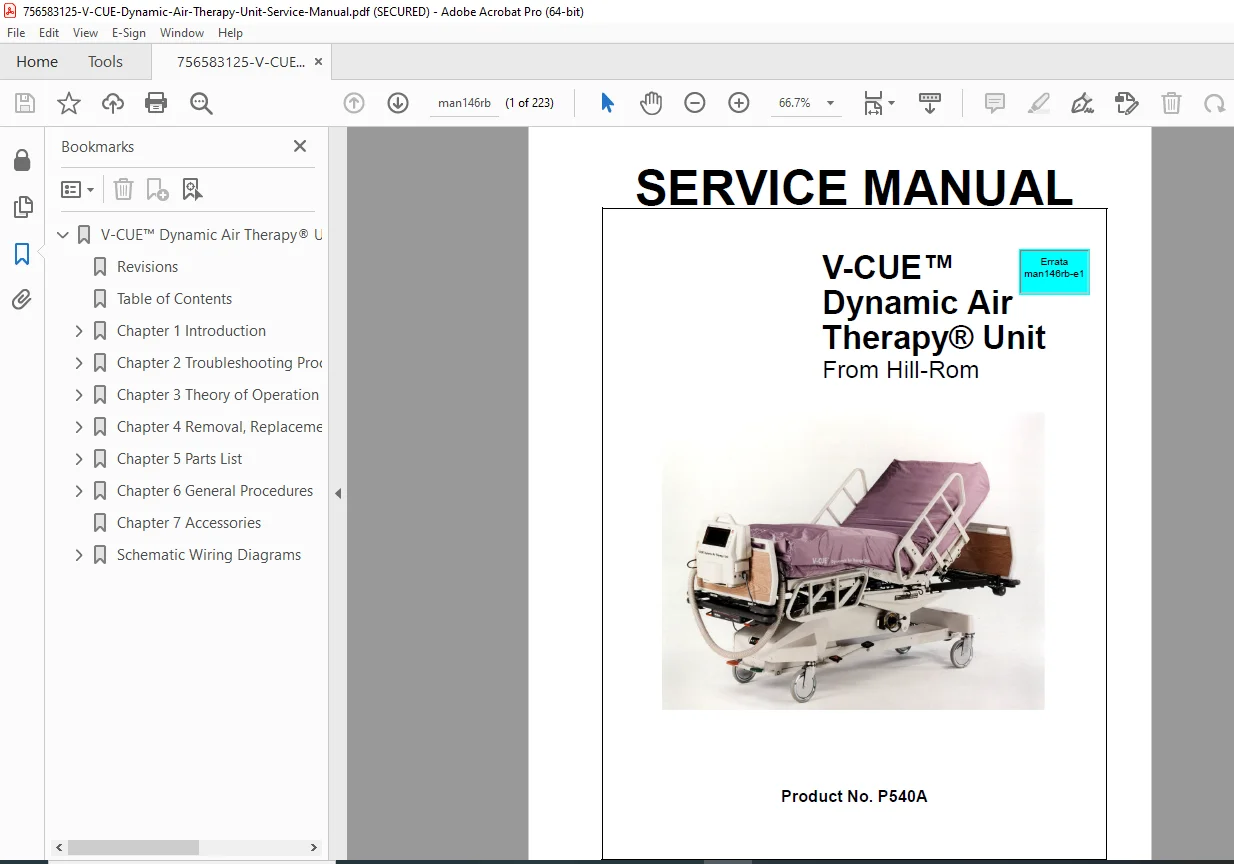
Hill-Rom V-CUE™ Dynamic Air Therapy® Unit – Official Factory Service Manual
This is the official Hill-Rom factory service manual for the V-CUE™ Dynamic Air Therapy® Unit — a comprehensive Hill-Rom V-CUE repair, troubleshooting, and parts reference guide for biomedical engineers and facility-authorized service technicians. Covering everything from AC/DC voltage fault diagnosis to proportional valve replacement and EPROM servicing, this manual is the definitive technical resource for maintaining Hill-Rom dynamic air therapy mattress systems in clinical environments.
📋 File Details
| Detail | Info |
|---|---|
| Manual Name | V-CUE™ Dynamic Air Therapy® Unit Service Manual |
| Manual Number | man146rb (Revision B) |
| Product Number | P540A series (P540A60, P540A77, P540A83, P540A84, P541A001, P541A026) |
| Manufacturer | Hill-Rom Services, Inc. |
| Year | December 2000 (Third Edition) |
| PDF Quality | High quality, text-searchable, fully bookmarked |
| Total Pages | 223 pages |
| File Format | |
| Voltage Models | 120V AC 60Hz (USA/Canada) & 230V model |
📚 Table of Contents
Chapter 1 – Introduction
- Purpose, audience, and manual organization
- Product overview & V-CUE unit description
- Key features:
- Therapy overrides
- Comfort control
- Cushion pressure management
- Menu system overview
- Physical specifications (dimensions, weight)
- Electrical specifications – 120V AC ±10%, 60Hz; 230V model; UL 2601-1, CSA C22.2 compliance
- Regulatory compliance – UL 2601, IEC 60601-1 Class I Type B, EU Directive 93/42/EEC, IEC/EN 60601-1-2 EMC
- Environmental conditions (operating, storage, transport)
- Model identification table (P540A series variants)
- Safety tips for facility-authorized personnel
- Warning and caution label locations
Chapter 2 – Troubleshooting Procedures
- Getting started – initial actions and function checks
- Error code / solution reference table (Table 2-1)
- Functional test observations table (Table 2-2)
- Final actions and repair verification
- Fault-by-fault troubleshooting procedures:
- 2.1 AC Voltage Malfunction – power cord test points, circuit breaker switch location, power cord receptacle connections
- 2.2 DC Voltage Malfunction – air supply unit case voltage checks
- 2.3 Control Panel Malfunction – control panel signal verification
- 2.4 Blower Malfunction – battery charger PC board checks
- 2.5 Cushion Inflation Malfunction – feed tube inspection, cushion/valve relationship table, valve information screen
- 2.6 Maximum Inflate Malfunction – beeper wiring diagnosis
- 2.7 CPR Malfunction
- 2.8 Rotation Malfunction – siderail sensor connectors, valve information screen
- 2.9 OPTI•REST Mode Malfunction – OPTI-REST mode screen, valve pressure readings table
- 2.10 Low Battery / Battery Charger Malfunction – air supply unit case checks
Chapter 3 – Theory of Operation
- Voltage distribution diagrams – AC and DC voltage distribution (120V & 230V models)
- Integrated wiring diagram
- Plug/jack connection diagrams:
- Battery Charger PC Board
- P/V Valve PC Board
- Left Proportional Valve PC Board
- Right Proportional Valve PC Board
- System theory:
- Air Supply Unit – mechanical, electrical (120V & 230V), and pneumatic components
- Recommended pressure levels table
- Air supply hose routing
- Mattress Assembly – cushion layout, hose management, hose connections
- Left & right proportional valve hose routing diagrams
- Percussion/Vibration hose routing diagram
- Software menu system – full menu hierarchy including Service Menu, Diagnostic Menu, Unit Settings, and Setup Menu detail diagrams
Chapter 4 – Removal, Replacement & Adjustment Procedures
Step-by-step illustrated removal and replacement procedures for all serviceable components:
- 4.1 Air Supply Unit Case
- 4.2 Battery
- 4.3 Battery Charger PC Board
- 4.4 Beeper Cable Assembly
- 4.5 Blower Motor
- 4.6 Power Cord Receptacle
- 4.7 Circuit Breaker Assembly
- 4.8 Control Panel
- 4.9 Control Panel Bezel Assembly
- 4.10 Control Panel Extension Cable Receptacle
- 4.11 Control Panel EPROM
- 4.12 On/Off Indicator Lamp
- 4.13 Printer Port Connector
- 4.14 Proportional Valve Assembly (Head Left / Head Right)
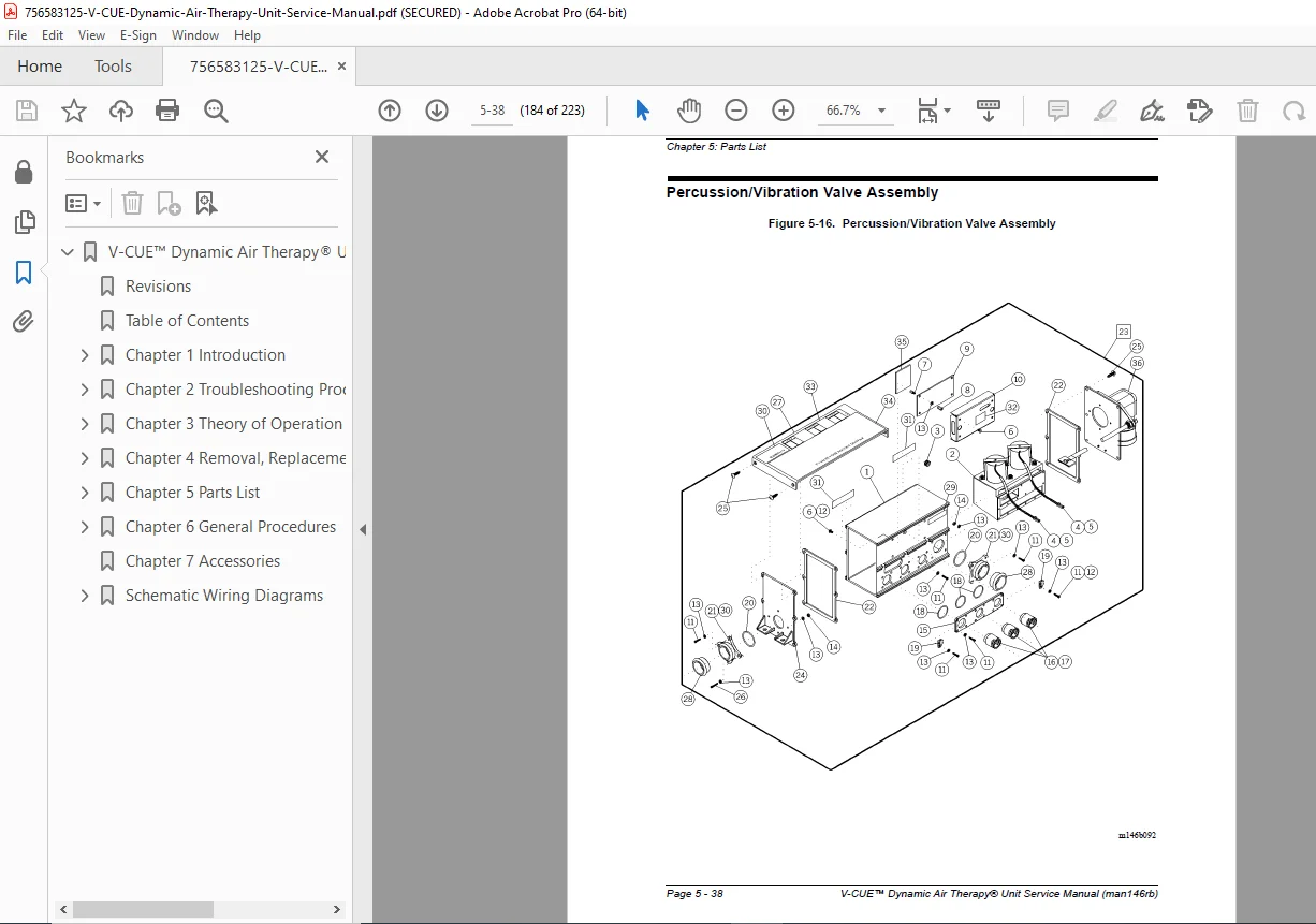
- 4.15 Percussion/Vibration (P/V) Valve Assembly
- 4.16 P/V Valve Solenoid PC Board Assembly & Heat Sink Pad
- 4.17 P/V Valve Assembly Air Supply Hose Interface Elbow
- 4.18 Power Supply
- 4.19 Siderail Position Sensor Assembly
- 4.20 Sensor Adapter Cable
Chapter 5 – Parts List
- Warranty and service parts ordering information
- Exchange policy (in-warranty & out-of-warranty)
- Recommended spare parts list (Table 5-1)
- Illustrated parts lists with diagrams and part number tables:
- Air Supply Unit (P541A001 & P541A026)
- Front Case Assembly
- Rear Case Assembly
- Front & Rear Case Foam Subassemblies
- Mattress Assembly & Subassembly (P451A08)
- Internal Mattress Hose Assembly
- V-CUE Unit (P540A60, P540A77, P540A83, P540A84)
- Air Supply Hose (P451A05)
- Percussion/Vibration Front Cover Assembly
- Blower/Bracket Assembly – 120V & 230V models
- Cradle Hose Assembly
- Sleep Surface Bolster Hose Assembly
- Percussion/Vibration Valve Assembly
- Control Panel Assembly
- Proportional Valve Assembly
- Labels, Hanger Assemblies, Transport Case, Fold-Flat Cart
Chapter 6 – General Procedures
- Cleaning – general, steam cleaning, hard-to-clean spots, disinfecting
- Mattress assembly component cleaning, coverlet care, cushion care, PC board handling
- Pre-Installation Maintenance (PIM)
- Routine maintenance schedule
- Transportation, setup, and pickup procedures – patient set-up screen reference
- Software operational procedures:
- Service Options Menu – alarm adjustment, setup options, diagnostics, service center info, unit settings, history buffer, screen contrast
- Diagnostics Menu – valve information, blower information, function test, battery information, boost/vent solenoid, valve operation stats, run diagnostics
- Diagnostics Test Menu – LCD display test, control panel LED test, display & system RAM test, program ROM test, control panel key test
- Cushion deflation procedure
Chapter 7 – Accessories
Appendix – Schematic Wiring Diagrams
- Integrated Wiring Diagram – 120V model
- Integrated Wiring Diagram – 230V model
- Hose Management Diagram
Every minute a Hill-Rom V-CUE unit is down is a minute patient care is compromised — this official 223-page service manual gives biomedical technicians every fault code, wiring diagram, valve procedure, and parts reference needed to diagnose and restore the unit to full operation fast. Download instantly and start servicing with confidence.