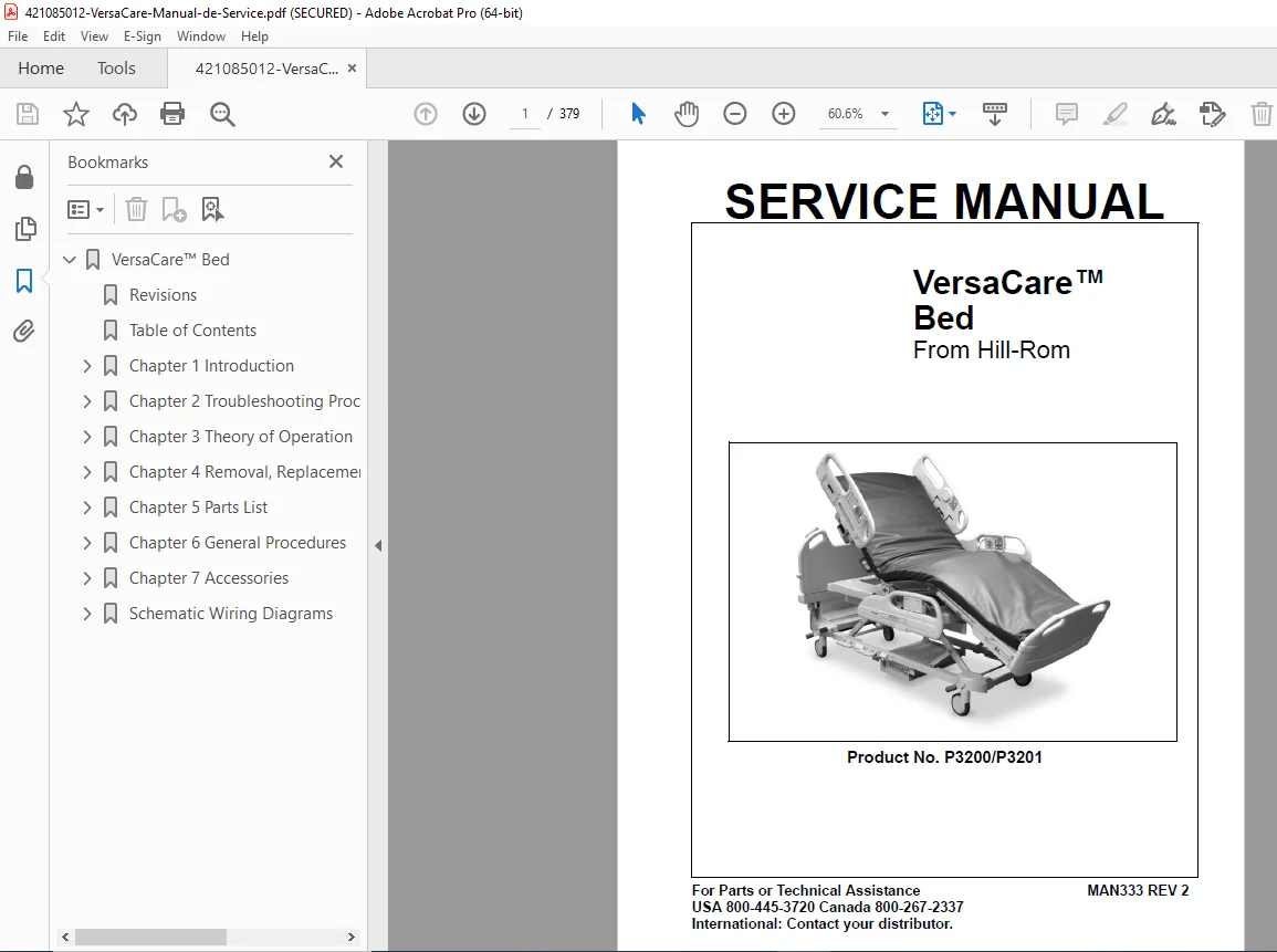
Hill-Rom VersaCare Bed Service Manual PDF DOWNLOAD
Original price was: $110.00.$32.95Current price is: $32.95.
Official Hill-Rom service manual for VersaCare hospital bed models P3200 and P3201. This complete 379-page technical manual provides comprehensive troubleshooting procedures, diagnostic LED codes, removal/replacement instructions, electrical schematics, parts lists, and theory of operation for all bed systems including IntelliDrive transport, air surface mattress, patient position monitoring, scale systems, and SideCom communication. Essential reference for biomedical technicians and hospital maintenance engineers.
Description
Hill-Rom VersaCare Bed Service Manual P3200 P3201 Hospital Bed Repair PDF DOWNLOAD
DESCRIPTION
Hill-Rom VersaCare™ Bed Complete Service Manual – Professional Technical Reference
This is the official Hill-Rom service manual (MAN333 REV 2) for VersaCare hospital bed systems, providing the most comprehensive technical documentation available for servicing, diagnosing, and repairing advanced medical bed equipment used in healthcare facilities worldwide.
📋 FILE DETAILS
- Manual Title: VersaCare™ Bed Service Manual
- Manual Part Number: MAN333 REV 2
- Models Covered: P3200, P3201
- Manufacturer: Hill-Rom Company, Inc.
- Publication Date: January 2005 (Revision 2)
- Total Pages: 379 pages
- PDF Quality: High-resolution professional scan
- Language: English
📖 COMPREHENSIVE TABLE OF CONTENTS
Chapter 1: Introduction (Pages 1-1 to 1-15)
- Purpose and Audience – Intended for qualified biomedical technicians
- Manual Organization and navigation guide
- Document Symbol Definitions for safety warnings and cautions
- VersaCare Bed Overview with system description
- Complete Specifications:
- Physical dimensions and weight capacities
- Electrical description (voltage, current, power requirements)
- Regulations, standards, and codes compliance (UL, CSA, IEC)
- Model identification and serial number locations
- Safety Tips for service personnel
- Warning and Caution Labels location guide
Chapter 2: Troubleshooting Procedures (Pages 2-1 to 2-78)
Comprehensive diagnostic procedures including:
Electronic Systems Troubleshooting:
- Getting started with systematic troubleshooting approach
- Initial actions and rapid problem/solution identification tables
- Function checks for all bed systems
- Treatment surface function verification
- Logic P.C. board diagnostic LED codes interpretation
- Bootloader, supervisory relay, and EEPROM failure diagnostics
- Head, knee, hilow lockout LED error codes
- Motor unexpected motion diagnostics (hilow, head, knee, leg, foot)
- Motor overcurrent protection troubleshooting
- Position rate errors (high and low)
- Absolute minimum drive current failure
- Network heartbeat failure system level
- Patient pendant causing logic P.C. board failure
- Logic circuit failure diagnostics
- Nuisance trip troubleshooting
- Power supply error codes and diagnostics
Power Systems Diagnostics:
- Motors do not operate troubleshooting
- No AC power diagnostics
- AC power present but no motor power
- No DC power troubleshooting
- Power supply error code interpretation
Control Systems:
- Siderail controls not working
- Siderail detection switch with/without SideCom® communication
- Patient pendant troubleshooting
- Obstacle detection system diagnostics
Air Surface Systems (Sheets 1-2):
- System error diagnostics with flash code interpretation
- Mattress disconnected troubleshooting
- Head angle sensor error
- FSR1 and FSR2 sensor diagnostics
- Accumulator pressure verification
- Missing 24V DC input troubleshooting
- Zone pressure diagnostics (head, seat, foot)
- Turn assist pressure troubleshooting (right and left)
Scale and Monitoring Systems:
- Scale error codes 0 through 5 (including European scale)
- Patient position monitor with/without scale display
- CRC error troubleshooting
IntelliDrive® Transport System:
- Bed will not drive diagnostics
- Wheel deployment and stow troubleshooting
- Battery check procedures
- Steer switch verification
- PACM board power, deployment, and drive checks
- Motor diagnostics
- Cable continuity checks
- Handle enable switch testing
- Throttle verification
- Handle gauge checks (3-sheet procedure)
- Controller debugging
- Visual inspection procedures
- Junction board debugging
Chapter 3: Theory of Operation (Pages 3-1 to 3-18)
Complete system descriptions:
Mechanical Systems:
- Base frame module construction and function
- Hilow lift module operation
- Upper frame module design
- User interface module layout
- End panel module components
Electrical Systems:
- Logic and motor control architecture
- Power supply design and operation
- User interface electronics
- Patient pendant circuitry
- SideCom® communication system protocol
- Scale and patient position monitor integration
- IntelliDrive® transport system electronics
- Pneumatic control systems
Complete Schematics:
- Electronics overview schematic
- Motor control P.C. board (PN 68717) detailed schematic
- Logic control P.C. board (PN 69378) circuit diagram
- Siderail controls wiring diagram
- Optional controls schematic
- Patient controls wiring
- Patient pendant circuit diagram
- Power supply (PN 72289) schematic
Chapter 4: Removal, Replacement, and Adjustment Procedures (Pages 4-1 to 4-100+)
Step-by-step procedures for servicing:
Tool and Supply Requirements
Major Components:
- Mattress removal and replacement
- Caster replacement procedures
- CPR cable removal, replacement, and adjustment
- Head siderail service procedures
- Intermediate siderail service
- Load beam removal and replacement
- Battery replacement procedures
Electronic Components:
- Head siderail P.C. board
- Speaker replacement
- Patient control P.C. board
- Control pod P.C. board
- Power supply P.C. board
- Logic control board
- Motor control board
Motor Systems:
- Foot hilow motor replacement
- Head hilow motor service
- Head section motor procedures
- Knee section motor replacement
- Foot motor service
- Foot extend motor procedures
Electrical Components:
- AC power fuses replacement
- Transformer and battery fuse service
- Power cord replacement
- Night light replacement
- Foot pedal assembly service
Pneumatic Systems:
- Air compressor removal and replacement
- Air module service procedures
Chapter 5: Parts List (Comprehensive)
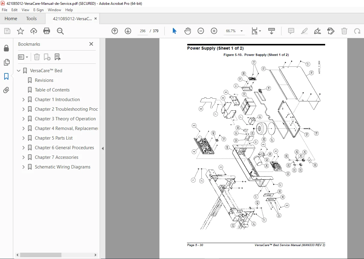
- Complete illustrated parts breakdown with part numbers
- Component identification and cross-references
- Assembly diagrams
- Parts ordering information
Chapter 6: General Procedures
- Preventive maintenance schedules
- Cleaning and decontamination procedures
- Pre-delivery inspection checklists
- Function test procedures
- Safety inspection protocols
Chapter 7: Accessories
- Compatible accessory systems
- Optional equipment integration
- Accessory installation procedures
🔧 KEY SYSTEMS COVERED
Bed Articulation Systems:
- Head section elevation mechanism
- Knee section adjustment system
- Foot section controls
- Hilow (bed height) adjustment system
- CPR quick-release mechanism
- Auto-contour and cardiac chair positioning
Patient Safety Features:
- Siderail detection and lockout systems
- Obstacle detection sensors
- Patient position monitoring
- Scale integration for patient weighing
- Brake and caster control systems
IntelliDrive® Transport System:
- Powered bed mobility system
- Steering control mechanism
- Battery-powered drive motors
- Deployment and stow mechanisms
- Handle controls and safety interlocks
Air Surface Technology:
- Multi-zone air mattress system
- Pressure adjustment controls
- Turn assist bladders (left/right)
- Head angle sensing
- Force sensing resistors (FSR)
- Accumulator pressure system
Communication Systems:
- SideCom® communication protocol
- Network integration capabilities
- Patient pendant interface
- Nurse call integration
Power and Control:
- AC power distribution
- DC power conversion
- Battery backup system
- Logic control processing
- Motor control electronics
👨🔧 WHO SHOULD USE THIS MANUAL
- Biomedical Equipment Technicians (BMETs) – For hospital bed maintenance and repair
- Hospital Clinical Engineering Staff – Managing medical equipment fleets
- Healthcare Facility Maintenance Teams – Ensuring patient care equipment reliability
- Medical Equipment Service Companies – Providing third-party service support
- Technical Training Instructors – Teaching hospital bed service procedures
- Quality Assurance Personnel – Conducting safety inspections and compliance checks
🏥 APPLICATIONS & FACILITIES
VersaCare beds are deployed in:
- Acute care hospitals and medical centers
- Intensive care units (ICU)
- Progressive care units (PCU)
- Medical-surgical floors
- Long-term acute care hospitals (LTACH)
- Rehabilitation facilities
- Post-acute care facilities
- Veterans Administration hospitals
⚡ TECHNICAL CAPABILITIES DOCUMENTED
Advanced Diagnostics:
- LED diagnostic code interpretation for rapid fault isolation
- Systematic troubleshooting flowcharts
- Component-level testing procedures
- Electrical measurement specifications
- Signal trace diagrams
Precision Adjustments:
- Motor current calibration
- Position sensor alignment
- Pressure transducer calibration
- Communication protocol verification
- Safety switch adjustment
Preventive Maintenance:
- Lubrication specifications
- Component inspection intervals
- Performance verification tests
- Safety system validation
- Electrical safety testing
📐 COMPLIANCE & STANDARDS
This manual covers equipment compliant with:
- UL 60601-1 Medical Electrical Equipment standards
- CSA C22.2 No. 601.1 Canadian requirements
- IEC 60601-1 International medical device standards
- FDA medical device regulations
- Hospital safety codes and requirements
💡 WHY THIS MANUAL IS ESSENTIAL
This official Hill-Rom service manual is the authoritative technical reference containing proprietary diagnostic procedures, detailed schematics, and precise repair instructions not available elsewhere. With 379 pages of comprehensive technical information including diagnostic LED codes, troubleshooting flowcharts for every system, complete electrical schematics, and step-by-step component replacement procedures, this manual enables you to restore critical patient care equipment to optimal functionality while maintaining safety compliance. Download immediately and have instant access to the exact technical specifications, wiring diagrams, and repair procedures you need to minimize bed downtime and ensure patient safety in your healthcare facility.
Pricing Rationale: This is a comprehensive 379-page professional service manual for sophisticated hospital bed equipment with multiple integrated systems (mechanical, electrical, pneumatic, electronic controls, communication systems). The manual contains proprietary technical information essential for maintaining critical patient care equipment worth tens of thousands of dollars. The extensive troubleshooting procedures, complete schematics, diagnostic codes, and component-level repair instructions justify premium pricing. Similar Hill-Rom medical equipment service manuals typically range from $39.95-$54.95 based on complexity and page count.