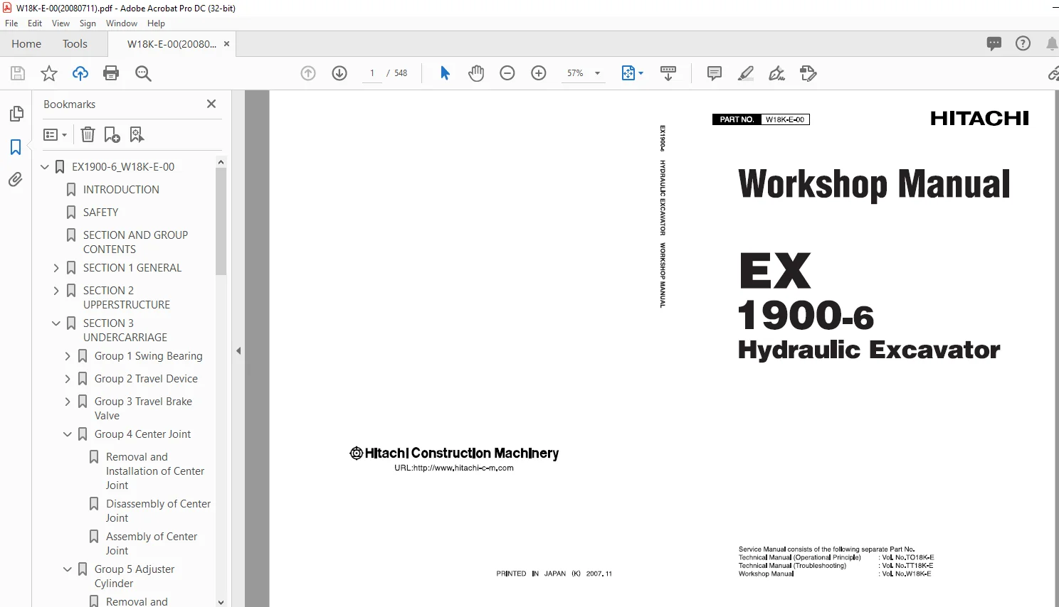
Hitachi 1900-6 Hydraulic Excavator Parts Manual W1 BK-E-00 – PDF DOWNLOAD
$30.95
Hitachi 1900-6 Hydraulic Excavator Parts Manual W1 BK-E-00 – PDF DOWNLOAD
Description
Hitachi 1900-6 Hydraulic Excavator Parts Manual W1 BK-E-00 – PDF DOWNLOAD
FILE DETAILS:
Hitachi 1900-6 Hydraulic Excavator Parts Manual W1 BK-E-00 – PDF DOWNLOAD
Language :English
Pages :548
Downloadable : Yes
File Type : PDF
IMAGES PREVIEW OF THE MANUAL:
DESCRIPRION:
Hitachi 1900-6 Hydraulic Excavator Parts Manual W1 BK-E-00 – PDF DOWNLOAD
INTRODUCTION
TO THE READER
Hitachi 1900-6 Hydraulic Excavator Parts Manual W1 BK-E-00 – PDF DOWNLOAD
EX1900-6_W18K-E-00 1
INTRODUCTION 3
SAFETY 5
SECTION AND GROUP CONTENTS 35
SECTION 1 GENERAL 37
Group 1 Precautions for Disassembling and Assembling 39
Precautions for Disassembling and Assembling 39
Maintenance Standard Terminology 45
Group 2 Tightening 47
Tightening Torque Specification 47
Torque Chart 49
Piping Joint 52
Periodic Replacement of Parts 56
Group 3 Painting 57
Painting 57
Group 4 Bleeding Air from Hydraulic Oil Tank 63
Bleeding Air from Hydraulic Oil Tank 63
SECTION 2 UPPERSTRUCTURE 67
Group 1 Cab 69
Removal and Installation Cab 69
Dimensions of the Cab Glass 72
Group 2 Counterweight 79
Removal and Installation of Counterweight 79
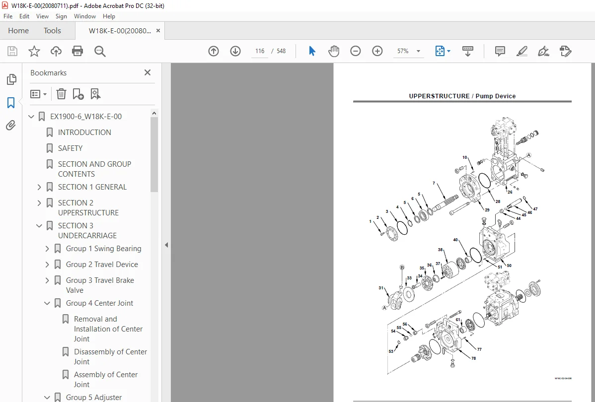
Group 3 Pump Device 83
Removal and Installation of Pump Device 83
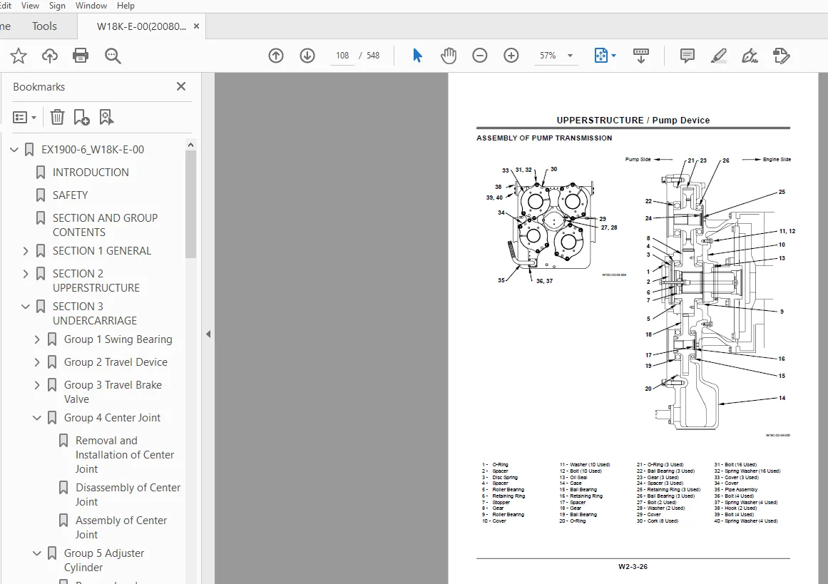
Disassembly of Pump Transmission104
Assembly of Pump Transmission108
Disassembly of Main Pump112
Assembly of Main Pump120
Maintenance Standard128
Disassembly of Regulator for Main Pump130
Assembly of Regulator for Main Pump136
Structure of 4-Spool Pump143
Disassembly of Oil Cooler Fan Drive Pump144
Assembly of Oil Cooler Fan Drive Pump148
Maintenance Standard154
Disassembly of Regulator for Oil Cooler Fan Drive Pump156
Assembly of Regulator for Oil Cooler Fan Drive Pump162
Disassembly of Air ConditionerCompressor Drive Pump and Pilot Pump168
Assembly of Air ConditionerCompressor Drive Pump and Pilot Pump174
Maintenance Standard178
Disassembly of Pump Transmission Oil Lubrication Pump180
Assembly of Pump Transmission Oil Lubrication Pump182
Maintenance Standard184
Group 4 Control Valve185
Removal and Installation of Control Valve185
Disassembly of Control Valve190
Assembly of Control Valve198
Disassembly and Assembly of Main Relief Valve and Overload Relief Valve202
Structure of Make-Up Valve204
Group 5 Swing Device205
Removal and Installation of Swing Device205
Disassembly of Swing Device212
Assembly of Swing Device220
Disassembly of Swing Motor232
Assembly of Swing Motor236
Maintenance Standard240
Disassembly and Assembly of Valve Unit242
Group 6 DQR Valve245
Removal and Installation DQR Valve245
Structure of DQR Valve248
Group 7 Shuttle Valve251
Removal and Installation of Shuttle Valve251
Structure of Shuttle Valve253
Group 8 EHC Valve255
Removal and Installation of EHC Valve255
Structure of EHC Valve261
Disassembly and Assembly of Proportional Solenoid Valve262
Structure of Solenoid264
Group 9 Oil Cooler Fan Motor265
Removal and Installation of Oil Cooler Fan Motor265
Disassembly of Oil Cooler Fan Motor270
Assembly of Oil Cooler Fan Motor272
Maintenance Standard274
Group 10 Compressor Drive Motor275
Removal and Installation of Compressor Drive Motor275
Disassembly of Compressor Drive Motor278
Assembly of Compressor Drive Motor280
Group 11 Air Conditioner283
Work after Replacing Component283
Charge Air Conditioner with Refrigerant284
Group 12 Grease Pump293
Grease Pump Construction293
SECTION 3 UNDERCARRIAGE299
Group 1 Swing Bearing301
Removal and Installation of Swing Bearing301
Group 2 Travel Device303
Removal and Installation of Travel Device303
Disassembly of Travel Device312
Assembly of Travel Device326
Disassembly of Travel Motor338
Assembly of Travel Motor344
Maintenance Standard350
Disassembly and Assembly of Travel Mode Selection Valve352
Group 3 Travel Brake Valve355
Removal and Installation of Travel Brake Valve355
Disassembly of Travel Brake Valve360
Assembly of Travel Brake Valve362
Group 4 Center Joint365
Removal and Installation of Center Joint365
Disassembly of Center Joint372
Assembly of Center Joint374
Group 5 Adjuster Cylinder377
Removal and Installation of Adjuster Cylinder377
Disassembly of Adjuster Cylinder384
Assembly of Adjuster Cylinder386
Group 6 Front Idler389
Removal and Installation of Front Idler389
Disassembly of Front Idler394
Assembly Front Idler396
Maintenance Standard398
Group 7 Upper and Lower Rollers399
Removal and Installation of Upper/ Lower Rollers399
Disassembly of Upper Roller406
Assembly of Upper Roller408
Disassembly of Lower Roller410
Assembly of Lower Roller412
Maintenance Standard414
Group 8 Track417
Removal and Installation of Track417
Structure of Track421
Maintenance Standard422
Group 9 Accumulator423
Removal and Installation of Accumulator423
Disassembly of Accumulator426
Assembly of Accumulator428
Group 10 Welding Repair Procedure433
Welding Repair Procedure433
Welding Rod Specification434
Repair Track Shoe (Shoe Lug)435
Repair Front Idler438
Repair Sprocket440
SECTION 4 FRONT ATTACHMENT445
Group 1 Front Attachment447
Removal and Installation of Front Attachment447
Group 2 Cylinder479
Removal and Installation of Cylinder479
Disassembly of Cylinder513
Assembly of Cylinder522
Main Points to Bleed Air528
Maintenance Standard530
Group 3 Bushing and Point533
Removal and Installation of Bushing533
Maintenance Standard536
SERVICE MANUAL REVISION REQUEST FORM547
THE ATTACHED PATTERN LIST548
S.M 28/01/25