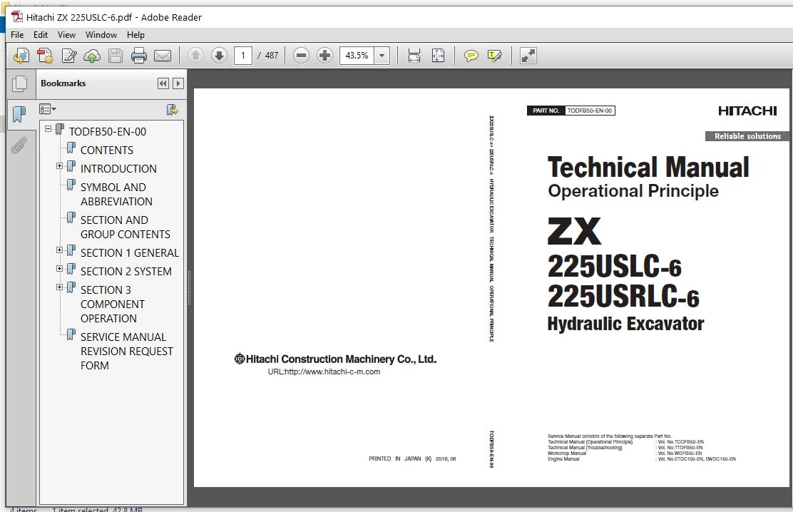
Hitachi 225USLC-6 225USRLC-6 Hydraulic Excavator Operational Principle Technical Manual – PDF Download
Original price was: $88.95.$28.95Current price is: $28.95.
- Hitachi 225USLC-6 225USRLC-6 Hydraulic Excavator Operational Principle Technical Manual
- Part No:TODFB50-EN-00
Description
Hitachi 225USLC-6 225USRLC-6 Hydraulic Excavator Operational Principle Technical Manual
File Details:
Hitachi 225USLC-6 225USRLC-6 Hydraulic Excavator Operational Principle Technical Manual
- Manual Language:English
- Pages: 487
- Size: 30.8 MB
- Downloadable:Yes
- Format:PDF
HITACHI 225USLC-6 225USRLC-6 HYDRAULIC EXCAVATOR OPERATIONAL PRINCIPLE TECHNICAL MANUAL – PDF DOWNLOAD:
Image Preview:
Description:
Hitachi 225USLC-6 225USRLC-6 Hydraulic Excavator Operational Principle Technical Manual
TO THE READER
This manual is written for an experienced technician to provide technical information needed to maintain and repair this machine. The machine specification and description according to destination may be explained on this manual.
• Be sure to thoroughly read this manual for correct product information and service procedures.
• If you have any questions or comments, at if you found any errors regarding the contents of this manual, please contact using “Service Manual Revision Request Form” at the end of this manual.
ADDITIONAL REFERENCES
Please refer to the other materials (operator’s manual, parts catalog, engine technical material and Hitachi training material etc.) in addition to this manual.
MANUAL COMPOSITION
This manual consists the Technical Manual and the Workshop Manual.
• Information included in the Technical Manual: technical information needed for redelivery and delivery, operation and activation of all devices and systems, operational performance tests, and troubleshooting procedures.
• Information included in the Workshop Manual: technical information needed for maintenance and repair of the machine, tools and devices needed for maintenance and repair, maintenance standards, and removal/installation and assemble/ disassemble procedures.
Table Of Contents:
Hitachi 225USLC-6 225USRLC-6 Hydraulic Excavator Operational Principle Technical Manual
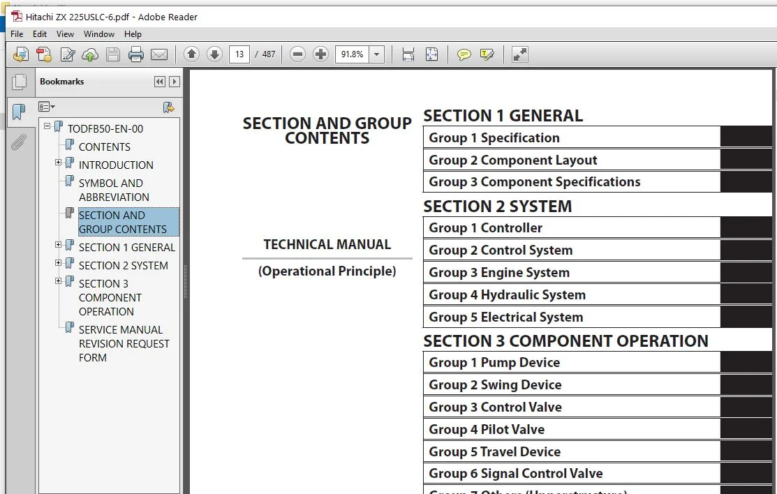
TODFB50-EN-00.................................................................................................  1
	CONTENTS
.................................................................................................  3
	INTRODUCTION..............................................................................................  9
		To The Reader.........................................................................................  9
		Additional References.................................................................................  9
		Manual Composition....................................................................................  9
		Page Number...........................................................................................  9
		Trademark.............................................................................................  9
		Safety Alert Symbol and Headline Notations............................................................ 10
		Units Used............................................................................................ 10
	SYMBOL AND ABBREVIATION................................................................................... 11
	SECTION AND GROUP CONTENTS................................................................................ 13
	SECTION 1 GENERAL......................................................................................... 15
		Group 1 Specifications................................................................................ 17
			Specifications.................................................................................... 17
			Working Ranges (Grouser shoe)..................................................................... 21
		Group 2 Component Layout.............................................................................. 25
			Main Component.................................................................................... 25
			Electrical System (Overview)...................................................................... 29
			Electrical System (Rear Tray)..................................................................... 30
			Electrical System (Switch Panel).................................................................. 31
			Electrical System (Utility Space)................................................................. 32
			Electrical System (Relays)........................................................................ 33
			Engine............................................................................................ 34
			Aftertreatment Device............................................................................. 35
			Pump Device....................................................................................... 36
			Around Pump Device................................................................................ 38
			Control Valve/Signal Control Valve................................................................ 39
			Swing Device...................................................................................... 41
			Travel Device..................................................................................... 41
			5-Spool Solenoid Valve Unit....................................................................... 42
			2-Spool Solenoid Valve Unit (Pilot Pressure Control (Pump 3 Flow Rate Control))................... 42
			2-Spool Solenoid Valve Unit (Aftertreatment Device Regeneration Control).......................... 42
			DEF Tank.......................................................................................... 43
			DEF Supply Module................................................................................. 43
			Layout of Attachment Spec. Parts.................................................................. 44
			Components Related with Breaker................................................................... 45
		Group 3 Component Specifications...................................................................... 49
			Engine............................................................................................ 49
			Engine Accessories................................................................................ 53
			Hydraulic Component............................................................................... 54
			Electrical Component.............................................................................. 58
			Optional Parts.................................................................................... 59
	SECTION 2 SYSTEM.......................................................................................... 65
		Group 1 Controller.................................................................................... 67
			Outline........................................................................................... 67
			CAN Circuit....................................................................................... 68
		Group 2 Control System................................................................................ 71
			Outline........................................................................................... 71
			Engine Control.................................................................................... 74
			Pump Control......................................................................................106
			Valve Control (Standard)..........................................................................130
			Valve Control (Optional)..........................................................................148
			Other Control.....................................................................................158
		Group 3 Engine System.................................................................................169
			ECM System........................................................................................169
			Fuel Injection Control............................................................................170
			Fuel Injection Amount Correction Control..........................................................178
			EGR Control.......................................................................................180
			Preheating Control................................................................................182
			Variable Turbocharger Control.....................................................................183
			Alarm Control.....................................................................................184
			Urea SCR System...................................................................................185
			Engine Output Restriction Control (INDUCEMENT)....................................................196
			Aftertreatment Device.............................................................................200
			Aftertreatment Device Regeneration Control........................................................202
		Group 4 Hydraulic System..............................................................................205
			Outline...........................................................................................205
			Pilot Circuit.....................................................................................206
			Main Circuit......................................................................................218
			Blade/Breaker/Pulverizer/Crusher Circuit (Option).................................................240
			Blade Circuit.....................................................................................242
		Group 5 Electrical System.............................................................................253
			Outline...........................................................................................253
			Main Circuit......................................................................................254
			Electric Power Circuit (Key Switch: OFF)..........................................................256
			CAN Circuit.......................................................................................258
			Accessory Related Circuit (Key Switch: ACC).......................................................260
			Starting Circuit (Key Switch: START)..............................................................262
			Charging Circuit (Key Switch: ON).................................................................264
			Surge Voltage Prevention Circuit..................................................................268
			Pilot Shut-Off Circuit (Key Switch: ON)...........................................................270
			Auto Shut-Down Circuit/Automatic Engine Stop Circuit at Low Temperature...........................272
			Engine Stop Circuit...............................................................................274
			Monitor Circuit...................................................................................277
			Security Circuit..................................................................................278
			Radio Circuit.....................................................................................280
			Air Conditioner Circuit...........................................................................280
			Accessory Circuit.................................................................................283
			Work Light Circuit................................................................................284
			Wiper/Washer Circuit..............................................................................286
			Cab Light Circuit.................................................................................288
	SECTION 3 COMPONENT OPERATION.............................................................................293
		Group 1 Pump Device...................................................................................295
			Outline...........................................................................................295
			Main Pump.........................................................................................296
			Regulator.........................................................................................300
			Solenoid Valve....................................................................................324
			Pilot Pump, Blade Pump (Option)...................................................................326
			Pump Delivery Pressure Sensor.....................................................................326
			Pump Control Pressure Sensor......................................................................326
		Group 2 Swing Device..................................................................................327
			Outline...........................................................................................327
			Swing Reduction Gear..............................................................................328
			Swing Motor.......................................................................................329
			Swing Parking Brake...............................................................................330
			Valve Unit........................................................................................332
		Group 3 Control Valve.................................................................................345
			Outline...........................................................................................345
			Hydraulic Circuit.................................................................................368
			Flow Combiner Valve...............................................................................374
			Main Relief Valve.................................................................................376
			Overload Relief Valve (with Make-Up Function).....................................................380
			Regenerative Valve................................................................................384
			Anti-Drift Valve..................................................................................394
			Flow Rate Control Valve...........................................................................398
			Digging Regenerative Valve........................................................................402
			Boom Lower Meter-In Cut Valve.....................................................................404
			Auxiliary Flow Combiner Valve and Bypass Shut-Out Valve...........................................406
			Blade Control Valve (Option)......................................................................410
			Blade Circuit (Option)............................................................................412
		Group 4 Pilot Valve...................................................................................415
			Outline...........................................................................................415
			Operation (Front Attachment/Swing and Travel Pilot Valves)........................................417
			Operation (Auxiliary, Blade, Positioning Pilot Valves)............................................425
			Shockless Function (Only for Travel Pilot Valve)..................................................430
		Group 5 Travel Device.................................................................................431
			Outline...........................................................................................431
			Travel Reduction Gear.............................................................................432
			Travel Motor......................................................................................434
			Parking Brake.....................................................................................436
			Travel Brake Valve................................................................................438
			Overload Relief Valve.............................................................................442
			Travel Mode Control...............................................................................444
		Group 6 Signal Control Valve..........................................................................449
			Outline...........................................................................................449
			Pilot Port........................................................................................450
			Shuttle Valve.....................................................................................455
			Shockless Valve...................................................................................458
			Pump 1 Flow Rate Control Valve, Pump 2 Flow Rate Control Valve, Pump 3 Flow Rate Control Valve....462
			Flow Combiner Valve Control Spool, Swing Parking Brake Release Spool..............................464
		Group 7 Others (Upperstructure).......................................................................465
			Pilot Shut-Off Solenoid Valve.....................................................................465
			Solenoid Valve....................................................................................467
			Hose Rupture Valve................................................................................472
			Pilot Relief Valve................................................................................478
			Recirculation Valve...............................................................................479
		Group 8 Others (Undercarriage)........................................................................481
			Swing Bearing.....................................................................................481
			Centerjoint.......................................................................................482
			Machine with Blade (Option) Equipped..............................................................483
			Track Adjuster (Front Idler Integrated Type)......................................................484
	SERVICE MANUAL REVISION REQUEST FORM......................................................................487
Please Note:
⦁ This is the same manual used by the dealers to diagnose and troubleshoot your vehicle
⦁ You will be directed to the download page as soon as the purchase is completed. The whole payment and downloading process will take anywhere between 2-5 minutes
⦁ Need any other service / repair / parts manual, please feel free to contact [email protected] . We still have 50,000 manuals unlisted