Hitachi CX1800 Crawler Crane Operational Principle+Troubleshooting+Workshop Manual – PDF DOWNLOAD
Original price was: $52.95.$26.95Current price is: $26.95.
Hitachi CX1800 Crawler Crane Operational Principle+Troubleshooting+Workshop Manual
This Listing includes all of the manuals mentioned below:
1.Hitachi CX1800 Crawler Crane Operational Principle Technical Manual
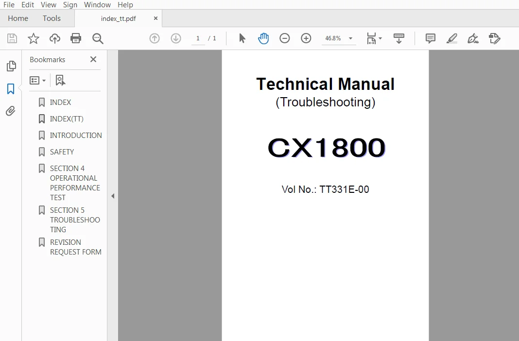
2.Hitachi CX1800 Crawler Crane Troubleshooting Technical Manual
3.Hitachi CX1800 Circuit Diagram & Harness
4.Hitachi CX1800 Crawler Crane Workshop Manual
Description
Hitachi CX1800 Crawler Crane Operational Principle+Troubleshooting+Workshop Manual
FILE DETAILS:
Hitachi CX1800 Crawler Crane Operational Principle+Troubleshooting+Workshop Manual
This Listing includes all of the manuals mentioned below:
1.Hitachi CX1800 Crawler Crane Operational Principle Technical Manual
2.Hitachi CX1800 Crawler Crane Troubleshooting Technical Manual
3.Hitachi CX1800 Circuit Diagram & Harness
4.Hitachi CX1800 Crawler Crane Workshop Manual
DESCRIPTION:
Hitachi CX1800 Crawler Crane Operational Principle+Troubleshooting+Workshop Manual
INTRODUCTION:
TO THE READER:
• This manual is written for an experienced technician to provide technical information needed to maintain and repair this machine.
• Be sure to thoroughly read this manual for correct product information and service procedures.
• If you have any questions or comments, at if you found any errors regarding the contents of this manual, please contact using “Service Manual Revision Request Form” at the end of this manual.
ADDITIONAL REFERENCES:
Please refer to the other materials (operator’s manual, parts catalog, engine technical material and Hitachi training material etc.) in addition to this manual
• Please refer to the materials listed below in addition to this manual.
• The Operator’s Manual
• The Parts Catalog
• The Engine Manual
• Parts Catalog of the Engine
• Hitachi Training Material
MANUAL COMPOSITION:
• This manual consists of three portions: the Technical Manual (Operational Principle), the Technical Manual (Troubleshooting) and the Workshop Manual.
• Information included in the Technical Manual (Operational Principle): technical information needed for redelivery and delivery, operation and activation of all devices and systems.
• Information included in the Technical Manual (Troubleshooting): technical information needed for operational performance tests, and troubleshooting procedures.
• Information included in the Workshop Manual: technical information needed for maintenance and repair of the machine, tools and devices needed for maintenance and repair, maintenance
standards, and removal/installation and assemble/ disassemble procedures.
TABLE OF CONTENTS:
Hitachi CX1800 Crawler Crane Operational Principle+Troubleshooting+Workshop Manual
- Hitachi CX1800 Crawler Crane Operational Principle Technical Manual
Group 1 Specification
SpecificationsT1-1-1
Group 2 Component Layout
Major Components T1-2-1
Electrical System (Inside Cab)T1-2-2
Electrical System (Outside Cab) T1-2-4
Pump DeviceT1-2-6
Hoist DeviceT1-2-7
Control ValveT1-2-9
Travel Device T1-2-13
Solenoid ValveT1-2-13
Group 3 Component Specifications
EngineT1-3-1
Engine AccessoryT1-3-4
Hydraulic Components T1-3-5
Electrical Parts T1-3-9
Group 1 Control System
Outline T2-1-1
Engine Control T2-1-2
Pump Control T2-1-6
Other Controls (By Main Controller and
Engine Controller)T2-1-18
Electrical/Hydraulic Combined
Circuit Control T2-1-28
Group 2 Hydraulic System
Outline T2-2-1
Main Circuit T2-2-2
Pilot CircuitT2-2-3
Reeving/Hydraulic Tagline
Brake Circuit (Optional) T2-2-4
Neutral Circuit T2-2-6
Hoist Circuit T2-2-8
Boom Hoist Circuit T2-2-17
Travel Circuit T2-2-19
Swing Circuit T2-2-23
Gantry Raise/Lower Circuit T2-2-24
Jack Up Circuit T2-2-24
Boom Foot Pin Remove/Install Circuit T2-2-24
Hoist Brake/Clutch Circuit T2-2-26
Pump Control Circuit T2-2-30
Group 3 Electrical System
Outline T2-3-1
Electric Power Circuit T2-3-2
Pre-Heat CircuitT2-3-3
Engine Start Circuit T2-3-4
Charging Circuit T2-3-9
Accessory CircuitT2-3-10
Engin Stop CircuitT2-3-11
Surge Voltage Preventive Circuit T2-3-15
Brake Control Circuit T2-3-16
Swing Brake Circuit T2-3-25
Group 1 Pump Device
Outline T3-1-1
Main PumpT3-1-2
Regulator T3-1-4
Pilot Pump and Reeving/Hydraulic
Tagline PumpT3-1-21
Pump Speed Sensor T3-1-21
Group 2 Swing Device
Outline T3-2-1
Swing Motor T3-2-2
Swing BrakeT3-2-4
Swing Reduction GearT3-2-5
Group 3 Hoist Device
Outline T3-3-1
Main Hoist Motor T3-3-2
Foot Brake T3-3-9
Hoist Brake T3-3-14
Counterbalance Valve T3-3-18
Clutch System T3-3-23
Group 4 Boom Hoist Device
Outline T3-4-1
Boom Hoist MotorT3-4-2
Boom Hoist Brake T3-4-4
Counterbalance Valve T3-4-6
Boom Host Reduction GearT3-4-11
Group 5 Control Valve
Outline T3-5-1
Hydraulic Circuit T3-5-8
Main Relief ValveT3-5-12
Make-Up Valve T3-5-14
Solenoid ValveT3-5-15
Group 6 Pilot Valve
Outline T3-6-1
Operation T3-6-5
Group 7 Travel Device
Outline T3-7-1
Travel Reduction GearT3-7-2
Travel Motor T3-7-3
Travel Brake Valve T3-7-5
Travel Motor Swash Plate
Tilt Angle Control T3-7-7
Parking BrakeT3-7-9
Group 8 Others (Superstructure)
Pilot Shut-Off Valve T3-8-1
Accumulator T3-8-2
8-Spool Solenoid ValveT3-8-3
Group 9 Others (Undercarriage)
Outline T3-9-1
Swing Bearing T3-9-2
Track Adjuster T3-9-3
Center JointT3-9-4
Side Frame Extend/Retract Cylinders T3-9-6
Jack Up Cylinder T3-9-7
- Hitachi cx1800 Crawler Crane Troubleshooting Technical Manual
Group 1 Introduction
Operational Performance Tests T4-1-1
Preparation for Performance
Tests T4-1-2
Precautions for Starting Engine T4-1-3
Group 2 Engine Test
Engine Speed T4-2-1
Engine Compression Pressure T4-2-2
Valve Clearance Adjustrment T4-2-4
Nozzle Check T4-2-6
Injection Timing T4-2-8
Group 3 Crane Test
Travel Speed T4-3-1
Mistrack T4-3-2
Travel Parking Brake Drift T4-3-3
Swing Speed T4-3-4
Swing Bearing Play T4-3-5
Hoist/Lower Speeds
(Main and Auxiliary Drums) T4-3-6
Boom Hoist Speed T4-3-7
Main/Auxiliary Hoist Drum
Motor Brake Drift T4-3-8
Lever Operating Force T4-3-9
Lever Stroke T4-3-10
Group 4 Component Test
Pilot Primary Pressure T4-4-1
Pilot Secondary Pressure T4-4-3
Travel Fast/Slow Speed Control Pressure
(SE Pressure) T4-4-4
Swing Brake Release Pressure
(SI Pressure) T4-4-5
Hydraulic System Relief Pressure T4-4-6
Overload Relief Valve Pressure T4-4-16
Main/Aux Hoist Motor Sequence Valve
Control Pilot Pressure T4-4-17
Main Pump Flow Rate T4-4-18
Swing Motor Drainage T4-4-26
Travel Motor Drainage T4-4-28
Boom Hoist Motor Drainage T4-4-30
Group 5 Standard
Performance Standard Table T4-5-1
Injection Pump T4-5-4
Group 1 Diagnosing Procedure
Introduction T5-1-1
Diagnosing Procedure T5-1-2
Group 2 Component Layout
Major Components T5-2-1
Electrical System (Inside Cab) T5-2-2
Electrical System (Outside Cab) T5-2-4
Pump Device T5-2-6
Hoist Device T5-2-7
Control Valve T5-2-9
Travel Device T5-2-13
Solenoid Valve T5-2-13
Group 3 Troubleshooting A
Troubleshooting A Procedure T5-3-1
Monitor Indicator Display and
Failure Type T5-3-2
Failure in Main Controller System T5-3-3
Failure in Engine Controller System T5-3-6
Malfunction of Swing Power
Compensation Control T5-3-11
Malfunction of Boom Hoist Slow
Stop Control T5-3-14
Malfunction of Boom Hoist
Speed Control T5-3-20
Malfunction of Hoist Speed Control T5-3-24
Malfunction of Drum Speed Sensing T5-3-28
Malfunction of Swing Speed Control T5-3-31
Malfunction of Jack Up Flow
Rate Control T5-3-38
Group 4 Troubleshooting B
Troubleshooting B Procedure T5-4-1
Engine Troubleshsooting T5-4-2
Actuator Control System
Troubleshooting T5-4-12
Hoist Drum Control Troubleshooting T5-4-14
Boom Hoist Drum Control
Troubleshooting T5-4-34
Swing System Troubleshooting T5-4-36
Travel System Troubleshooting T5-4-38
Other Control Troubleshooting T5-4-41
Auto-Stop Controller Display T5-4-47
- Hitachi CX1800 Crawler Crane Workshop Manual
Group 1 Precautions for Disassembling
and Assembling
Precautions for Disassembling and
Assembling W1-1-1
Group 2 Tightening Torque
Tightening Torque Specification W1-2-1
Standard Torque Specifications W1-2-2
Piping Joint W1-2-5
Group 1 Cab
Remove and Install Cab W2-1-1
Cab Pane Dimensions W2-1-7
Group 2 Counterweight
Remove and Install Counterweight W2-2-1
Group 3 Main Frame
Remove and Install Superstructure W2-3-1
Group 4 Pump Device
Remove and Install Pump Device W2-4-1
Disassemble Pump Device W2-4-4
Assemble Pump Device W2-4-6
Remove and Install Main Pump W2-4-8
Disassemble Main Pump W2-4-10
Assemble Main Pump W2-4-16
Maintenance Standard W2-4-20
Disassemble Regulator W2-4-22
Assemble Regulator W2-4-26
Disassemble and Assemble
Pilot Pump W2-4-28
Group 5 Control Valve
Remove and Install 3 and 4-Spool
Control Valves (Main Hoist, Aux Hoist,
Travel, and Auxiliary) W2-5-1
Remove and Install 3-Spool Control Valve
(Gantry Raise/Lower, Jack Control,
and Boom Footpin Remove/Install) W2-5-3
Remove and Install 1-Spool Control Valve
(Boom Hoist) W2-5-5
Remove and Install 1-Spool Control Valve
(Swing Device) W2-5-7
Disassemble 4-Spool Control Valve W2-5-10
Assemble 4-Spool Control Valve W2-5-12
Disassemble 3-Spool Control Valve W2-5-14
Assemble 3-Spool Control Valve W2-5-16
Disassemble 3-Spool Control Valve W2-5-18
Assemble 3-Spool Control Valve W2-5-20
Disassemble 1-Spool Control Valve
(Boom Hoist) W2-5-22
Assemble 1-Spool Control Valve
(Boom Hoist) W2-5-24
Disassemble 1-Spool Control Valve
(Swing Device) W2-5-26
Assemble 1-Spool Control Valve
(Swing Device) W2-5-28
Group 1 Swing Bearing
Remove and Install Swing Bearing W3-1-1
Disassemble and Assemble
Swing Bearing W3-1-4
Group 2 Travel Device
Remove and Install Travel Device W3-2-1
Disassemble Travel Device W3-2-4
Assemble Travel Device W3-2-8
Disassemble Travel Motor W3-2-14
Assemble Travel Motor W3-2-18
Disassemble Brake Valve W3-2-22
Assemble Brake Valve W3-2-24
Maintenance Standard W3-3-26
Group 3 Center Joint
Remove and Install Center Joint W3-3-1
Disassemble Center Joint W3-3-4
Assemble Center Joint W3-3-6
Maintenance Standard W3-3-8
Group 4 Track Adjuster
Remove and Install Track Adjuster W3-4-1
Disassemble and Assemble
Track Adjuster W3-4-2
Group 5 Front Idler
Remove and Install Front Idler W3-5-1
Disassemble Front Idler W3-5-2
Assemble Front Idler W3-5-4
Maintenance Standard W3-5-6
Group 6 Upper and Lower Roller
Remove and Install Upper Roller W3-6-1
Remove and Install Lower Roller W3-6-2
Disassemble Upper Roller W3-6-4
Assemble Upper Roller W3-6-6
Disassemble Lower Roller W3-6-8
Assemble Lower Roller W3-6-10
Maintenance Standard W3-6-12
Group 7- Track
Remove and Install Track W3-7-1
Maintenance Standard W3-7-4
Group 8- Side Frame Extend/Retract
Cylinder
Remove and Install
Extend/Retract Cylinder W3-8-1
Disassemble Extend/Retract Cylinder W3-8-4
Assemble Extend/Retract Cylinder W3-8-6
General Information
General Repair Instructions I-2
Notes on the format of this Manual I-2
Main Data and Specifications 1-6
Performance Curve 1-7
Engine External View 1-9
Design Features and General Outline 1-13
Tightening Torque Specifications 1-14
Angular Nut and Bolt Tightening Method 1-16
Major Parts Fixing Nuts and Bolts 1-18
Identifications 1-28
Maintenance
Lubricating System 2-2
Fuel System 2-3
Cooling System 2-8
Valve Clearance Adjustment 2-9
Injection Timing 2-11
Compression Pressure Measurement 2-13
Turbocharger Inspection 2-14
Engine Repair Kit 2-15
Recommended Lubricants 2-16
Engine Oil Viscosity Chart 2-16
Engine AssemblyⅠ(Disassembly)
General Description3-2
Disassembly First Step 3-3
Disassembly Second Step 3-6
Disassembly Third Step3-9
Cylinder Head Disassembly Step 3-13
Piston and Connecting Rod
Disassembly Step 3-15
Rocker Arm and Shaft Disassembly Step 3-17
Camshaft and Gear Disassembly Step 3-17
Crankshaft Disassembly Step 3-18
Engine Assembly Ⅱ (Inspection and
Repair)
Cylinder Head4-2
Valve Guide 4-3
Valve and Valve Seat Insert 4-4
Valve Spring 4-8
Tappet 4-9
Push Rod 4-10
Rocker Arm Shaft and Rocker Arm 4-10
Idler Gear and Idler Gear Shaft 4-11
Camshaft 4-12
Cylinder Body and Liner 4-13
Piston and Piston Ring 4-18
Piston Pin 4-19
Connecting Rod 4-20
Crankshaft and Bearings 4-22
Flywheel and Flywheel Housing 4-29
Timing Gear Case Cover 4-30
HITACHI CX1800 CRAWLER CRANE OPERATIONAL PRINCIPLE+TROUBLESHOOTING+WORKSHOP MANUAL – PDF DOWNLOAD:
IMAGES PREVIEW OF THE MANUAL:
PLEASE NOTE:
- This is the same manual used by the DEALERSHIPS to SERVICE your vehicle.
- The manual can be all yours – Once payment is complete, you will be taken to the download page from where you can download the manual. All in 2-5 minutes time!!
- Need any other service / repair / parts manual, please feel free to contact us at heydownloadss @gmail.com . We may surprise you with a nice offer