Hitachi EX 1900E-6 Hydraulic Excavator Operational & Technical Manual PT TOKBC-EN-00 – PDF DOWNLOAD
$29.95
Hitachi EX 1900E-6 Hydraulic Excavator Operational & Technical Manual PT TOKBC-EN-00 – PDF DOWNLOAD
Description
Hitachi EX 1900E-6 Hydraulic Excavator Operational & Technical Manual PT TOKBC-EN-00 – PDF DOWNLOAD
FILE DETAILS:
Hitachi EX 1900E-6 Hydraulic Excavator Operational & Technical Manual PT TOKBC-EN-00 – PDF DOWNLOAD
Language :English
Pages :290
Downloadable : Yes
File Type : PDF
IMAGES PREVIEW OF THE MANUAL:
DESCRIPRION
Hitachi EX 1900E-6 Hydraulic Excavator Operational & Technical Manual PT TOKBC-EN-00 – PDF DOWNLOAD
- This manual is written for an experienced technician to provide technical information needed to maintain and repair this machine. The machine specification and description according to destination may be explained on this manual.
- Be sure to thoroughly read this manual for correct product information and service procedures.
- ‘ If you have any questions or comments, at if you found any errors regarding the contents of this manual, please contact using “Service Manual Revision Request Form” at the end of this manual.
MANUAL COMPOSITION
- This manual consists the Technical Manual and the Workshop Manual.
- Information included in the Technical Manual: technical information needed for redelivery and delivery, operation and activation of all devices and systems, operational performance tests, and troubleshooting procedures.
- Information included in the Workshop Manual: technical information needed for maintenance and repair of the machine, tools and devices needed for maintenance and repair, maintenance standards, and removal/installation and assemble/ disassemble procedures.
Hitachi EX 1900E-6 Hydraulic Excavator Operational & Technical Manual PT TOKBC-EN-00 – PDF DOWNLOAD
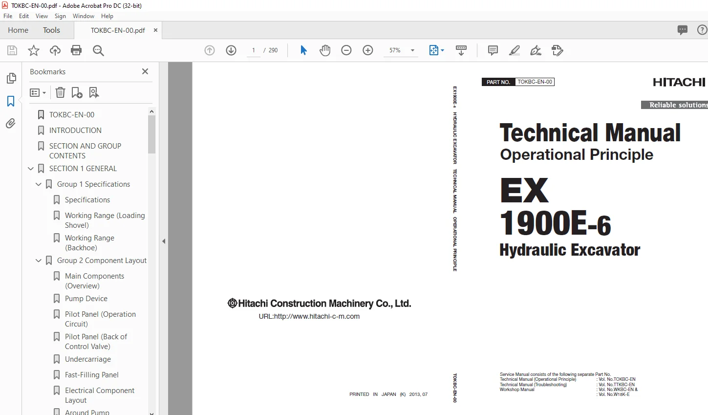
TOKBC-EN-00 1
INTRODUCTION 3
SECTION AND GROUP CONTENTS 5
SECTION 1 GENERAL 7
Group 1 Specifications 9
Specifications 9
Working Range (Loading Shovel) 10
Working Range (Backhoe) 11
Group 2 Component Layout 13
Main Components (Overview) 13
Pump Device 15
Pilot Panel (Operation Circuit) 16
Pilot Panel (Back of Control Valve) 17
Undercarriage 18
Fast-Filling Panel 19
Electrical Component Layout 21
Around Pump 32
Control Valve 33
Travel Device 36
Center Joint 36
Swing Device 37
EHC Valve (Main Pump Control) 38
EHC Valve (Electric Lever Control) 39
Hydraulic Oil Tank 40
Oil Cooler 41
Retractable-Type Ladder 42
Auto-Lubrication Device 43
Electrical Component Layout (6600 V) 44
Electric Motor 45
Cubicle 46
Group 3 Component Specifications 49
Electric Motor 49
Hydraulic Equipment 53
Electrical Component 57
Filter 60
Others 60
SECTION 2 SYSTEM 63
Group 1 Controller 65
Outline 65
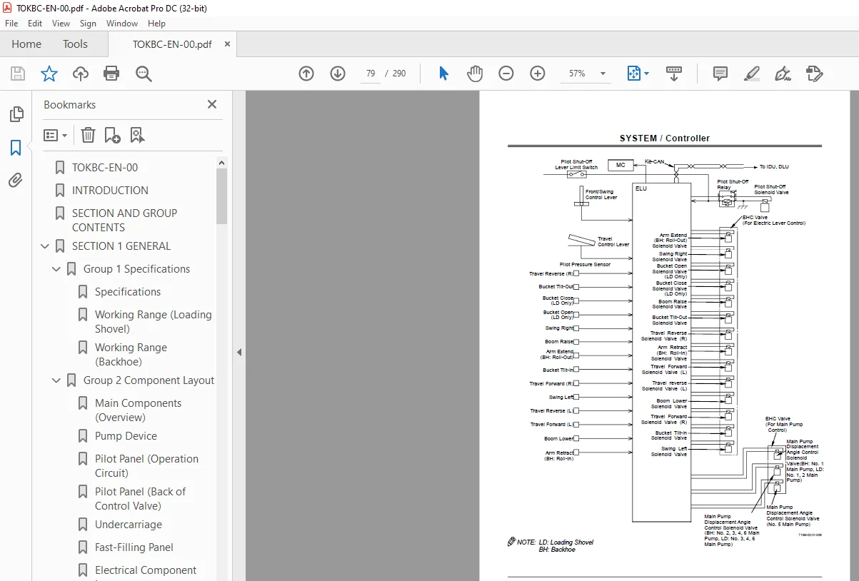
MC: Main Controller 66
ELU: Electric Lever Control Unit 74
IDU: Information Display Unit 80
DLU: Data Logging Unit 86
CSU: Contamination Sensing Unit 88
HMU: Hydraulic System Monitoring Unit (Pump/Swing Motor Drain Pressure Monitoring Unit) 90
Group 2 Control System 93
Outline 93
Auto-Lubrication Control 94
Oil Cooler Fan Motor Speed Control 98
Wiper Control100
Travel Mode Control102
Group 3 ELU System105
Outline105
Pilot Shut-off Control106
Pump Control108
Cushion Cylinder End Travel Regulation Control110
Swing Stop Control112
Group 4 Hydraulic System115
Outline115
Main Circuit116
Pilot Circuit128
Pump Transmission Oil Cooling Circuit134
Oil Cooler Fan Motor Circuit134
Travel Shock Damper / Travel Stop Circuit135
Group 5 Electrical System137
Outline137
Electric Power Circuit (Key Switch: OFF)138
Accessory Circuit (Key Switch: ACC)140
Main Motor Start Circuit142
Charging Circuit (Key Switch: ON)146
Main Motor Stop Circuit156
Delay Circuit For Power Off162
Group 6 Electrical System (6600 V)165
Outline165
Construction166
High-Voltage Circuit168
Main Motor Start Circuit170
Main Motor Stop Circuit178
Cab Heater Power Circuit182
Battery Charge Detection Circuit183
210 V Voltage Detection Circuit184
Cubicle Space Heater Start Circuit186
Air Conditioner Compressor Motor Circuit187
Interlock Circuit189
SECTION 3 COMPONENT OPERATION205
Group 1 Pump Device207
Outline207
Main Pump208
Regulator (Main Pump)210
Regulator (Oil Cooler Fan Motor Drive Pump)211
4-Unit Pump233
Contamination Sensor234
Group 2 Swing Device235
Outline235
Swing Motor236
Swing Parking Brake238
Swing Reduction Gear239
Valve Unit240
Group 3 Control Valve243
Outline243
Pilot Port Location244
Hydraulic Circuit245
Main Relief Valve and Overload Relief Valve247
Make-Up Valve248
Group 4 Control Equipment249
Outline249
Electric Lever250
EHC Valve (For Electric Lever Control)254
Group 5 DQR Valve257
Outline257
Port Location258
Construction259
Operation260
Group 6 Travel Device263
Outline263
Travel Motor264
Travel Mode Control266
Brake Valve268
Parking Brake270
Travel Reduction Gear271
Group 7 Others (Upperstructure)273
Air Conditioning System273
Auto-Lubrication System275
EHC Valve (For Main Pump Control)276
Oil Cooler Fan Motor278
Accumulator279
Group 8 Others (Undercarriage)281
Swing Bearing281
Adjuster Cylinder282
Accumulator283
Center Joint285
SERVICE MANUAL REVISION REQUEST FORM289
S.M 28/01/25