Hitachi EX1200-5C Excavator Technical Operational Principle Manual (T018EE-00) – PDF Download
Original price was: $87.95.$26.95Current price is: $26.95.
- Hitachi EX1200-5C Excavator Technical Operational Principle Manual
- Part No:T018EE-00
Description
Hitachi EX1200-5C Excavator Technical Operational Principle Manual (T018EE-00)
File Details:
Hitachi EX1200-5C Excavator Technical Operational Principle Manual (T018EE-00)
- Manual Language:English
- Pages: 246
- Size: 5.08 MB
- Downloadable:Yes
- Format:PDF
HITACHI EX1200-5C EXCAVATOR TECHNICAL OPERATIONAL PRINCIPLE MANUAL (T018EE-00) – PDF DOWNLOAD:
Image Preview:
Description:
Hitachi EX1200-5C Excavator Technical Operational Principle Manual (T018EE-00)
TO THE READER
• This manual is written for an experienced technician to provide technical information needed to maintain and repair this machine.
• Be sure to thoroughly read this manual for correct product information and service procedures.
• If you have any questions or comments, at if you found any errors regarding the contents of this manual, please contact using “Service Manual Revision Request Form” at the end of this manual
ADDITIONAL REFERENCES
• Please refer to the materials listed below in addition to this manual.
• The Operator’s Manual
• The Parts Catalog
• Operation Manual of the Engine
• Parts Catalog of the Engine
• Hitachi Training Material
MANUAL COMPOSITION
• This manual consists of three portions: the Technical Manual (Operational Principle), the Technical Manual (Troubleshooting) and the Workshop Manual.
• Information included in the Technical Manual (Operational Principle): technical information needed for redelivery and delivery, operation and activation of all devices and systems.
• Information included in the Technical Manual (Troubleshooting): technical information needed for operational performance tests, and troubleshooting procedures.
• Information included in the Workshop Manual: technical information needed for maintenance and repair of the machine, tools and devices needed for maintenance and repair, maintenance standards, and removal/installation and assemble/ disassemble procedures.
Table Of Contents:
Hitachi EX1200-5C Excavator Technical Operational Principle Manual (T018EE-00)
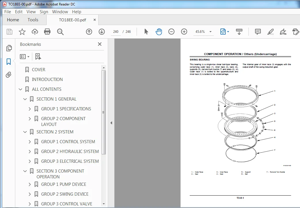
COVER.........................................................................................  1
INTRODUCTION..................................................................................  2
ALL CONTENTS..................................................................................  4
	SECTION 1 GENERAL.........................................................................  6
		GROUP 1 SPECIFICATIONS................................................................  8
			SPECIFICATIONS....................................................................  8
			WORKING RANGE (BACKHOE)........................................................... 10
			WORKING RANGE (BE BACKHOE)........................................................ 11
			WORKING RANGE (LOADING SHOVEL).................................................... 12
			ENGINE............................................................................ 13
			ENGINE ACCESSORIES................................................................ 16
			HYDRAULIC DEVICES................................................................. 16
			ELECTRICAL EQUIPMENT.............................................................. 19
		GROUP 2 COMPONENT LAYOUT.............................................................. 22
			MAIN COMPONENTS................................................................... 22
			ELECTRICAL SYSTEM COMPONENTS (1).................................................. 23
			ELECTRICAL SYSTEM COMPONENTS (2).................................................. 24
			ELECTRICAL SYSTEM COMPONENTS (3).................................................. 29
			ELECTRICAL SYSTEM COMPONENTS (4).................................................. 30
			ON AND AROUND PUMPS............................................................... 31
			OTHERS............................................................................ 32
	SECTION 2 SYSTEM.......................................................................... 36
		GROUP 1 CONTROL SYSTEM................................................................ 38
			OUTLINE........................................................................... 38
			ENGINE CONTROL.................................................................... 39
			PUMP CONTROL...................................................................... 51
			VALVE CONTROL..................................................................... 57
			OIL COOLER FAN MOTOR CONTROL...................................................... 65
			AUTO-LUBRICATION CONTROL.......................................................... 67
		GROUP 2 HYDRAULIC SYSTEM.............................................................. 70
			OUTLINE........................................................................... 70
			PILOT CIRCUIT..................................................................... 71
			MAIN CIRCUIT...................................................................... 89
			PUMP TRANSMISSION OIL COOLING CIRCUIT.............................................117
			OIL COOLER FAN MOTOR CIRCUIT......................................................117
		GROUP 3 ELECTRICAL SYSTEM.............................................................118
			OUTLINE...........................................................................118
			POWER SOURCE CIRCUIT..............................................................119
			BULB CHECK CIRCUIT................................................................120
			ENGINE START CIRCUIT..............................................................121
			CHARGING CIRCUIT (KEY SWITCH: ON).................................................125
			ACCESSORY CIRCUIT.................................................................127
			SURGE VOLTAGE PREVENTION CIRCUIT..................................................129
	SECTION 3 COMPONENT OPERATION.............................................................134
		GROUP 1 PUMP DEVICE...................................................................136
			OUTLINE...........................................................................136
			MAIN PUMP, OIL COOLER FAN MOTOR DRIVE PUMP........................................137
			REGULATORS........................................................................140
			3-UNIT PUMP.......................................................................161
		GROUP 2 SWING DEVICE..................................................................162
			OUTLINE...........................................................................162
			SWING MOTOR.......................................................................163
			VALVE UNIT........................................................................165
			SWING PARKING BRAKE...............................................................167
			SWING REDUCTION GEAR..............................................................168
		GROUP 3 CONTROL VALVE.................................................................170
			OUTLINE...........................................................................170
			HYDRAULIC CIRCUIT.................................................................179
			FLOW COMBINER VALVE...............................................................181
			MAIN RELIEF VALVE.................................................................183
			OVERLOAD RELIEF VALVE.............................................................184
			MAKE-UP VALVE.....................................................................184
			HOLDING VALVE.....................................................................185
			ARM REGENERATIVE VALVE............................................................187
			BOOM OVERLOAD RELIEF PRESSURE SWITCH VALVE........................................189
		GROUP 4 PILOT VALVE...................................................................192
			OUTLINE...........................................................................192
			OPERATION.........................................................................193
		GROUP 5 TRAVEL DEVICE.................................................................200
			OUTLINE...........................................................................200
			TRAVEL REDUCTION GEAR.............................................................201
			TRAVEL MOTOR......................................................................202
			TRAVEL BRAKE VALVE................................................................204
			TRAVEL MOTOR DISPLACEMENT ANGLE CHANGE............................................209
			PARKING BRAKE.....................................................................211
		GROUP 6 SIGNAL CONTROL VALVE..........................................................214
			OUTLINE...........................................................................214
			PILOT PORT........................................................................215
			SHUTTLE VALVE.....................................................................219
			SHOCKLESS VALVE...................................................................223
			PUMP 1 AND 2 FLOW RATE CONTROL
VALVE.............................................227
			ARM FLOW RATE CONTROL VALVE, FLOW COMBINER VALVE CONTROL SPOOL, PRIORITY VALVE....229
		GROUP 7 OTHERS(UPPERSTRUCTURE)........................................................230
			PILOT SHUT-OFF VALVE..............................................................230
			SHOCKLESS VALVE...................................................................231
			SOLENOID VALVE....................................................................235
			OIL COOLER FAN MOTOR..............................................................237
			ACCUMULATOR.......................................................................238
			AUTO-LUBRICATION SYSTEM...........................................................239
		GROUP 8 OTHERS(UNDERCARRIAGE).........................................................240
			SWING BEARING.....................................................................240
			CENTER JOINT......................................................................241
			TRACK ADJUSTER....................................................................242
	REVISION REQUEST FORM.....................................................................246
Please Note:
⦁ This is the SAME MANUAL used by the dealerships to diagnose your vehicle
⦁ No waiting for couriers / posts as this is a PDF manual and you can download it within 2 minutes time once you make the payment.
⦁ Your payment is all safe and the delivery of the manual is INSTANT – You will be taken to the DOWNLOAD PAGE.
⦁ So have no hesitations whatsoever and write to us about any queries you may have : heydownloadss @gmail.com